Service Station Drives
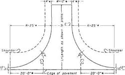
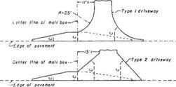
Service station drive approach geometry is probably the most complex of any drive design. Many of the geometric features may be used in the design of other commercial
|
|||||
|
|||||
|
|||||
|
|
||||
|
|||||
|
|||||
![]()

|
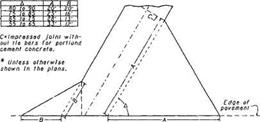
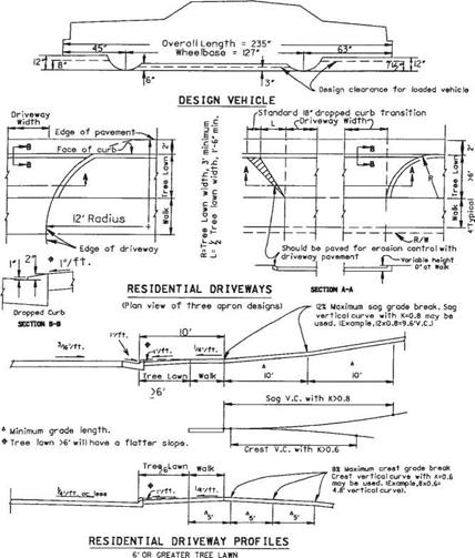
FIGURE 2.50 Details of driveway designs. Conversions: 1 ft = 0.305 m, 1 in = 25.4 mm. (From Location and Design Manual, Vol. 1, Roadway Design, Ohio Department of Transportation, with permission) |
and industrial drives. Figures 2.52 through 2.55 illustrate service station approach designs under varying conditions.
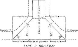
The location and angle of an approach in relation to an adjacent highway intersection should be such that a vehicle entering or leaving the site may turn out of or into the nearest lane of traffic moving in the desired direction and be channeled within this lane before entering the intersection or proceeding along the highway. The interior angle between the axes of dual approaches and the centerline of the roadway should fall between 45 and 90°. This interior angle should fall between 70 and 90° for single approaches designed for two-way operation. The width of all approaches should not be greater than 35 ft (11 m) in the throat of the approach measured at right angles to
![]()
![]()
 |
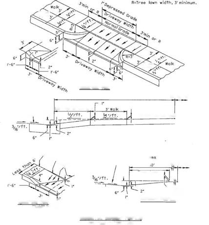 EXAMPLE: TREE LAWN AND WALK, LESS THAN 6′ WALK DEPRESSED Г
RESIDENTIAL DRIVEWAY PROFILES
LESS THAN 6′ TREE LAWN
FIGURE 2.51 Additional details of driveway designs. Conversions: 1 ft = 0.305 m, 1 in = 25.4 mm. (From Location and Design Manual, Vol. 1, Roadway Design, Ohio Department of Transportation, with permission) the axis of the approach. Where public alleys adjoin the service station property, approaches may begin at the far side of the alley, and if so used, the width of the alley should be included as part of the approach opening.
Approach radii on uncurbed highways should be as follows:
Turning radii: 15 ft (4.6 m) minimum, 25 to 50 ft (7.6 to 15.2 m) desirable Nonturning radii: 5 ft (1.5 m) minimum, 10 ft (3.0 m) maximum
Approach radii on curbed highways should be as follows:
Turning radii: 3 ft (0.91 m) minimum, 15 to 25 ft (4.6 to 7.6 m) desirable Nonturning radii: 3 ft (0.91 m) minimum, 5 ft (1.5 m) maximum
L 15′ or greater W 35′ maximum
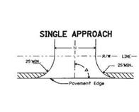 Л 70° to 90° (for approach with two-way operation) – O 45° to 90°
R’ Nonturning Radius,
5′ min. to!0′ max R" Turning Radius, 15’min,
25’to 50’Desirable r Permissible Rounding 15’max ч\\ Treated Shoulder

DUAL APPROACHES & INTERMEDIATE ISLAND
Where the approach radius controls the turning radius of a right-turning vehicle entering the service station from the adjacent traffic lane of the roadway, the radius of that edge should be as long as practical to provide a free and safe movement.


Leave a reply