Roadside Geometry
Except for flat roadsides, a motorist leaving the roadway may encounter a foreslope (negative grade such as on an embankment), a backslope (positive grade such as in a cut section), a transverse slope (such as caused by an intersecting side road), or a drainage channel (change from negative to positive grade).
Foreslopes parallel to the traffic flow may be categorized as recoverable, nonrecoverable, or critical. Recoverable slopes are 1:4 (vertical to horizontal) or flatter, and the
![]()
 |
|
 CLEAR-ZONE DISTANCE (m)
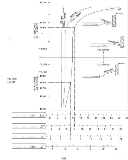
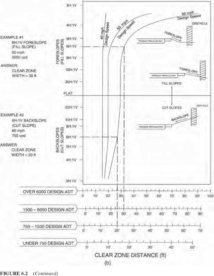
FIGURE 6.2 Clear zone distance curves. (a) SI units; (b) U. S. Customary units. (From Roadside Design Guide, AASHTO, Washington, D. C., 2002 and 2006, with permission) clear zone distance from Fig. 6.2 applies directly. Fixed obstacles such as culvert head – walls should not extend above the embankment in this zone. Nonrecoverable slopes, generally between 1:4 and 1:3, are traversable, but most motorists will reach the bottom of the slope and not be able to stop or return to the roadway easily. Fixed obstacles should not be constructed along such slopes, and a clear runout area at the bottom of the slope is desirable. Critical slopes, generally steeper than 1:3, are those on which a vehicle is likely to overturn. A barrier might be warranted in such cases. Figure 6.3 discusses alternatives that might be considered on critical parallel foreslopes.
|
|
Many highway agencies construct so-called barn roof sections in embankment conditions as illustrated in Fig. 6.4. A relatively flat slope is provided adjacent to the roadway, followed by a steeper slope and a clear runout area at the bottom. This is more economical than a continuous flat slope and apparently safer than a continuous steeper slope from the edge of the shoulder. In applying the clear zone concept, side slopes ranging from flat to 1:4 may be averaged to produce a composite clear zone distance. Slopes that change from negative to positive should be treated as channel sections. Changes in slope and toes of slopes should generally be rounded to keep vehicles in contact with the ground and enhance traversability.
EXAMPLE I
Design ADT: 12,000
Design Speed: 70 mph (110 km/h)
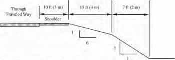
Keeonirnended dear-zone distance Гог I V:6II forcslopc: 30 to 34 ft (9 to 10.5 im
|
|
Discussion: Since the critical foreslopc is only 23 ft (7 no from the through traveled way. instead of die suggested 30 to 34 ft (9 lo 10.5 in), и should be flattened if practical or considered for shielding. However, if this is an isolated obstacle and the roadway has no significant crash history, it may be appropriate to do little more than delineate the drop-off in lieu of foreslope flattening or shielding
Although a "weighted" average of the foreslopcs may be used, a simple average of the clcar-zone distances for each foreslope is accurate enough if the variable foreslopcs arc approximately the same width II one foreslope is significantly wider, the clcar-zone computation based on that foreslope alone may be used.
EXAMPLE 2
Design ADT: 350
Design Speed: 40 mph (60 km/h)
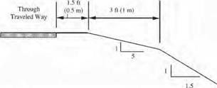
Recommended dear-zone distance for I V:5II foreslopc: 7 to 10 ft <2 to 3 rni
|
|
Discussion: The available 4.5 ft 11.5 in) is 2.5 to 5.5 ft (0.5 lo 1.5 ml less than the recommended recovery area. If much of this roadway has a similar cro&s-section and no significant run-off-the-roed crash history, neither foreslopc flattening nor a traffic barrier would be recommended On the oilier hand, even if the I V;5H foreslopc were 10 ft (3 m) w-idc and (he clcar-zone requirement were met. u traffic barrier might be appropriate it (his locution had noticeably less recovery area than the rest of the roadway and the embankment was unusually high.
FIGURE 6.3 Examples of application of clear zone concept to critical parallel foreslopes on (Example 1) high-volume and (Example 2) low-volume highways. (From Roadside Design Guide, AASHTO, Washington, D. C., 2002 and 2006, with permission.)
On backslopes, traversability depends on relative smoothness and the presence of fixed obstacles. If traversable (1:3 slope or flatter) and obstacle free, it may be acceptable. Conversely, a steep rough-sided rock cut (one that will cause excessive vehicle snagging) should be shielded unless it is outside the clear zone.
Transverse slopes may be created by median crossovers, intersecting side roads, or driveways. These generally create a more serious condition than parallel slopes because they can be struck head on by errant vehicles. To minimize the effect, slopes of 1:10
|
Clear zone distance |
Clear runout area required |
||||
|
Through traveled way |
Shoulder |
Recoverable slope |
Nonrecovera slope |
ble |
Clear runout area |
|
1:4 or flatter slope (1:6 or flatter desirable) |
Slopes between 1:3 and 1:4 |
1:6 or flatter slope desirable |
|||
|
FIGURE 6.4 Example of “barn roof’ section for parallel foreslope design; recoverable slope is followed by a nonrecoverable slope. (From Roadside Design Guide, AASHTO, Washington, D. C., 2002 and 2006, with permission) |
or flatter are desirable where practical. Steeper slopes may be suitable for low-speed facilities. Drainage pipes should be located as far from the roadway as practical. Also, where a vehicle could be led into the culvert inlet or outlet by a drainage channel, consideration should be given to special inlet or outlet treatment, as subsequently discussed.
Drainage channels are open flow areas generally paralleling the highway embankment within the right-of-way. They serve to collect surface runoff that drains from the highway and convey it to outlets. In addition to providing drainage functions, channels should be proportioned so that they are traversable. The shaded areas in Figs. 6.5 and 6.6 show preferred (traversable) slopes for the sides of channels. Where practical, channel sections outside the shaded areas may be reshaped, converted to a closed system (culvert), or shielded by a barrier. For all channels, roadside hardware (for example, sign supports) should not be located in or near channel bottoms or slopes because vehicles leaving the roadway may be funneled along the channel and impact the obstacle. Breakaway hardware may not function properly if impacted by airborne or sideways-sliding vehicles.


Leave a reply