Rigid Pipe
Introduction. There are two general types of rigid underground structures—those with a curvilinear shape, and those made up of straight walls and flat slabs. A reinforced concrete pipe is an example of the former, while a reinforced concrete box is an example of the latter. Rigid structures built in a curvilinear shape tend to act in compression. However, because of their limited deflection capability, they develop moment as well as compressive stresses. The effect of moment is reduced, however, because the curvilinear shape increases the compression in the member. Structures built with straight structural elements act very differently. The effect of moment on the individual members is so great that it is not unusual for the engineer to completely ignore any small benefit obtained from the compression of the member.
Circular rigid pipe may be designed by either the empirical D-load method, termed indirect design, or by an analytical method of direct design. If the pipe is designed by

 the indirect method, moments, thrust, and shears need not be determined. All that is necessary for the design is the total load on the pipe, the bedding factor as determined from the proposed bedding conditions, and the proposed inside and outside pipe diameters. If the pipe is designed by the direct method, the moments, thrust, and shears may be determined from charts prepared by the American Concrete Pipe Association (ACPA) and published in 1994 in its Concrete Pipe Technology Handbook. Otherwise they may be determined from more exact finite element methods using available computer programs. After the moments, thrust, and shears are determined, the required pipe wall thickness, concrete strength, and area of reinforcing steel may be determined.
American Society of Civil Engineers provides a specification titled Standard Practice for Direct Design of Buried Concrete Pipe Using Standard Installations (SIDD). This document presents a direct design method for reinforced concrete pipe based on extensive research using the finite element computer program Soil-Pipe Interaction Design and Analysis (SPIDA). The results of the studies are twofold. First, four standard installation types were developed, and second, a generalized pressure distribution was developed. These changes represent a major departure from the traditional Marston/Spangler installations and design method.
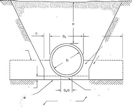
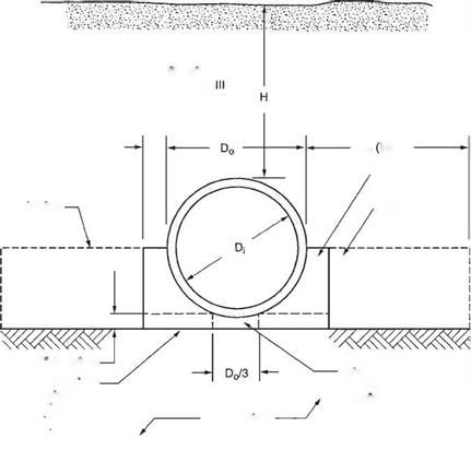
The four installation types can be applied to both a trench and an embankment installation. Unlike Marston/Spangler design theory, the SIDD method does not differentiate between these two installation types. The nomenclature used in SIDD is given in Figs. 5.34 and 5.35, standard installations for trenches and embankments, respectively.
Overfill Soil
Category I, II, III
Dn/6 Min.)
Haunch
Springline
Lower Side
![]()
Middle bedding loosely
![]() compaction each
compaction each
side, same
requirements
as haunch

Springline
requirements
as haunch
FIGURE 5.35 Standard embankment installation. (From Concrete Pipe Design Manual, American Concrete Pipe Association, 2007, with permission)
Note that the bedding detail requires the bedding under the middle one-third of the pipe diameter to be left uncompacted. This is so that the pipe can properly seat itself in the bedding, resulting in a greater length of support along the bottom circumference of the pipe.
SIDD is only intended for use on circular pipe. The ACPA recommends that arch and elliptical pipe be designed using traditional Marston/Spangler design methods.
Live Loads. As discussed in Art. 5.8.2, live loads are distributed through the cover above the top of the pipe. The ACPA computed live load distribution factors for critical loading cases using standard AASHTO methodologies as given in the Concrete Pipe Design Manual, American Concrete Pipe Association, 2007. The results are summarized as follows: The pressure at the crown of the pipe is
 All
All
where ctl = pressure intensity, lb/ft2 (kPa)
P = wheel load, lb (kN)
If = impact factor
All = distributed live load area, ft2 (m2) The total live load is
![]() W = WdLSL
W = WdLSL
where WL = total live load, lb (kN)
Wd = live load on pipe, lb/ft2 (kN/m2)
SL = outside pipe diameter or width of All transverse to longitudinal axis of pipe, whichever is less, ft (m)
L = length of All parallel to longitudinal axis of pipe, ft (m)
|
and
|
Please see the referenced ACPA manual for full details and for charts summarizing maximum live loads on reinforced concrete pipes.
For rigid structures where the cover is less than 2 ft (600 mm), the wheel load is applied as a concentrated load and there is no assumed distribution due to the fill. Since most concrete pipes have 2 ft (600 mm) or more of cover, this generally applies only to reinforced concrete box culverts or three-sided culverts. The distribution length longitudinally along the top slab of the structure for the wheel loads applied as concentrated loads is defined as the distance E, ft (mm), given by
E = 4 + 0.06S in U. S. Customary units (5.32a)
E = 1220 + 0.06S in SI units (5.32b)
where S is the span in ft (mm). The live load may be distributed to the bottom slab of a reinforced concrete box culvert over a longitudinal distance equal to the width of the top slab strip increased by twice the box height.
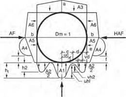
Load Distribution for Rigid Pipe. The pipe-soil system will distribute the applied earth load about the circumference of the pipe. The distribution is far from uniform. The SIDD specification includes an earth pressure distribution, sometimes called the Heger pressure distribution, for the distribution of loads about a concrete pipe. Figure 5.36 shows the pressure distribution as a function of several nondimensional arching factors and pressure distribution ratios. The figure also provides tabular data for the arching factors and pressure distribution ratios for each of the four standard installations. These factors are then multiplied by the soil prism load to obtain the magnitude of the pressures about the pipe. A full discussion on the development of the earth pressure distribution can be found in Concrete Pipe Technology Handbook, American Concrete Pipe Association, 1994.
The use of the SIDD earth pressure distribution requires that the soil types and compaction levels meet exact specifications. The soil material and compactions requirements and bedding thickness requirements for the four SIDD installations are given in Table 5.12. SIDD soil type designations are given in Table 5.13.
|

Notes:
1 VAF and HAF are vertical and horizontal arching factors These coefficients represent non
dimensional total vertical and horizontal loads on the pipe, respectively. The actual total vertical and horizontal loads are (VAF) X (PL) and (HAF) X (PL), respectively, where PL is the prism load.
2. PL, the prism load, is the weight of the column of earth cover over the pipe outside diameter and is calculated as:
![]() Do
Do
12
3. Coefficients A1 through A6 represent the integration of non-dimensional vertical and horizontal components of soil pressure under the indicated portions of the component pressure diagrams (i. e. the area under the component pressure diagrams). The pressures are assumed to vary either parabolically or linearly, as shown, with the non-dimensional magnitudes at governing points represented by hi, h2. uh1. vh2, aandb. Non-dimensional horizontal and vertical dimensions of component pressure regions are defined by c, d. e, vc, vd, and t coefficients
4. d is calculated as (0.5 -c-e).
hi is calculated as (1.5A1)/(c) (t+u). h2 is calculated as (1.5A2)/((d) (1+v) + (2e)J
|
TABLE 5.12 Standard Soils and Minimum Compaction Requirements for Concrete Pipe
*Compaction and soil symbols like “95% Category I” refer to “Category I soil material with minimum standard Proctor compaction of 95%.” Source: From Concrete Pipe Design Manual, American Concrete Pipe Association, 2007, with permission. |
|
TABLE 5.13 Equivalent USCS and AASHTO Soil Classifications for SIDD Soil Designations
|
Example: Earth Load on Concrete Pipe. A 60-in-diameter (1524-mm) concrete pipe with 6-in (152-mm) walls is to be installed under 12 ft (3.66 m) of cover using a SIDD Type 2 installation. The backfill is sandy silt compacted to a density of 120 lb/ft3 (19 kN/m3). Determine the vertical load acting at the crown and invert of the pipe and the horizontal load acting at the springline.
Calculate the soil prism load using Eq. (5.26) as
= 9104 lb/ft (133 kN/m)
From Fig. 5.36, for a Type 2 installation the crown VAF coefficient is 1.40 and the springline horizontal arching factor (HAF) coefficient is 0.40. Use Eq. (5.27) to determine the vertical design load:
WEV = VAF (Wc)
= 1.40 (9104)
= 12,746 lb/ft (186 kN/m)
Also use Eq. (5.27) to determine the horizontal design load:
Weh = HAF (Wc)
= 0.40 (9104)
= 3642 lb/ft (53 kN/m)
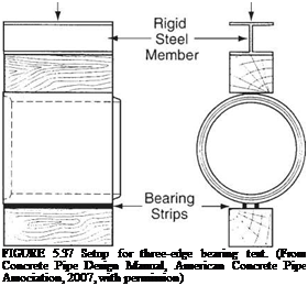
Structural Design of Concrete Pipe by Indirect Design. The indirect design method is an empirical method in which the pipe is tested by the three-edge bearing test (Fig. 5.37), and is subjected to a previously calculated load. If the pipe supports the application of the load without exceeding a crack width criterion of 0.01 in (2.5 mm), it is considered acceptable for the application for which it was manufactured. Even though AASHTO, ASCE, and ACPA promote the use of the SIDD direct design method for concrete pipe, the traditional indirect design method is still in widespread use.
The concept of the bedding factor is used in the indirect design method to relate the load-carrying capacity of an installed pipe to that of a pipe in a three-edge bearing test. In other words, the bedding factor is the ratio of the field applied load to the three-edge bearing load. For any given load, with a better installation, a lower-strength pipe is needed than would be required with an installation of poorer quality. The bedding factor is a function of the following:
1. The quality of the bedding material
2. The intimacy of contact between the bedding and the pipe
3. The length over which the bedding supports the pipe
4. The quality of side fill material
5. The length over which the side fill responds to pipe deflection with passive earth pressure
 |
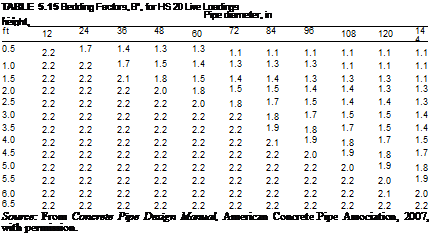
The ACPA conducted parametric studies of the four standard SIDD installations to determine appropriate bedding factors for use in the indirect design method. These values are presented in Table 5.14. More exact bedding factors for trench installations are published in Concrete Pipe Design Manual, American Concrete Pipe Association, 2007. When live loads control the design of a concrete pipe (less than 7 ft or 2.1 m of cover), a “bedding factor” for the live load must also be considered. These live load bedding factors are given in Table 5.15. Where the pipe is jacked, it maintains good contact in the area of the invert. In addition, it is common practice to grout outside the pipe after jacking operations are complete. Because of this, a bedding factor as high as 3 may be used for jacked pipe.
The load on the pipe is determined as discussed above and in Art. 5.8.2. The earth load is determined by adjusting the prism load by the arching factor. The earth load is combined with the structure dead load and any hydrostatic loads to obtain the total dead load. The dead load is then combined with the live load and impact load to obtain
Standard installation
|
TABLE 5.14 Bedding Factors for Dead Load under Embankment Conditions, Bro Pipe
Notes: (1) For pipe diameters other than those listed, embankment condition factors can be obtained by interpolation. (2) Bedding factors are based on the soils being placed with the minimum compaction specified. Source: From Concrete Pipe Design Manual, American Concrete Pipe Association, 2007, with permission. |
 |
the total load. The appropriate load to be applied to the pipe for the three-edge bearing test may be found by dividing the total load by the appropriate bedding factor as determined from the installation conditions. This final value is termed the required minimum three-edge bearing load (TEB). If the pipe is nonreinforced, a safety factor of between 1.25 and 1.5 should be applied to the load. This is because as soon as the nonreinforced pipe cracks, it has reached its ultimate strength. However, a reinforced concrete pipe has significant postcracking strength. There is a factor of 1.25 to 1.5 between the TEB load and the ultimate load for a reinforced concrete pipe, the factor varying with the pipe diameter.

![]() (5.33)
(5.33)
where WD = dead load, lb/ft (kN/m)
WL = live load + impact, lb/ft (kN/m)
BfD = dead load bedding factor (see Table 5.14)
BfL = live load bedding factor (see Table 5.15)
In the application of this equation, if the dead load bedding factor is greater than the live load bedding factor, then the dead load bedding factor should be used in lieu of the live load bedding factor.
Concrete pipe is typically specified by its D-load value (lb/ft/ft or kN/m/m) defined as follows:
![]() required TEB D-load = —-
required TEB D-load = —-
D
where Di = inside pipe diameter, ft (m)
Example: Concrete Pipe Design via Indirect Design. Using the same 60-in (1524-mm) concrete pipe from the previous example, determine the required D-load pipe for the 12 ft (3.66 m) of cover using a SIDD Type 2 installation. Assume a 5-in-thick (127-mm) pipe wall.
The earth load was previously determined to be 12,764 lb/ft (186 kN/m). With 12 ft (3.66 m) of cover, the live load is negligible. From Eq. (5.23a), the pipe load is
Wp = 3.3h (Dt + h)
= 3.3 (5) (60 + 5)
= 1073 lb/ft (16 kN/m)
From Table 5.14, the dead load bedding factor is 2.83; therefore, using Eq. (5.33), the three-edge bearing load is
![]() ——+ + ——+
——+ + ——+
BfD BfL
= 12,764 + 1073
2.83
= 4889 lb/ft (71 kN/m)
and from Eq. (5.34) the required D-load is
required TEB
D-load = —і—————-
Di
= 4889 5
= 978 lb/ft/ft (47 kN/m/m)
Structural Design of Concrete Pipe by Direct Design. The direct design procedure for analyzing a concrete pipe is based not on empirical methods, but on engineering analysis. Consequently, the engineer may determine precisely what strength of concrete, wall thickness, and reinforcement are necessary. However, the method is more complex and does not lend itself to direct hand calculations. The load on the pipe is determined in the same manner as for indirect design. Then the moments, thrusts, and shears can be calculated. The distribution of the load about the pipe is given by the Heger pressure distribution.
To encourage the use of the direct design method, the ACPA has published, in the Concrete Pipe Technology Handbook, a series of charts (see Table 5.16) presenting values of nondimensional coefficients Cm, Cni, and Cvi for each of the following load cases:
• Pipe load, Wp
• Earth load, We
• Water load, Wf
• Live load, WL
|
TABLE 5.16 Coefficients for Analysis of Concrete Pipe in Standard Installations
|
|
TABLE 5.16 Coefficients for Analysis of Concrete Pipe in Standard Installations (Continued)
|
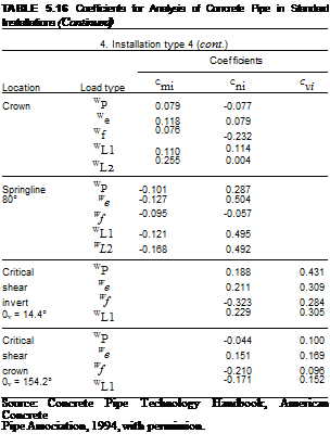 |
These coefficients are used to directly calculate the pipe wall moments, thrusts, and shears, respectively, for each of the four standard installations. The thrusts and shears can be computed by multiplying the magnitude of the load case by the corresponding Cni and Cvi coefficients. The moment calculation is more complex in that the resulting moment is computed by the following equation:
![]() M. = KC. ™
M. = KC. ™
i mi 2
where Mi = moment due to the pertinent load case, lb • ft/ft (kN • m/m)
Cmi = moment coefficient for the pertinent load case Wi = magnitude of the pertinent load case, lb/ft (kN/m)
D = mean pipe diameter, in (mm)
K = 1.0 for U. S. Customary units (0.0121 for SI units)
For more precise calculations, the designer can utilize the FHWA-developed computer program PIPECAR. The program gives calculated moments, thrusts, and shears. It will also design the pipe utilizing either direct or indirect design procedures. After determining the forces acting on the pipe, the wall thickness, concrete strength, and amount of reinforcing can be calculated. The software follows the detailed design provisions in the AASHTO Standard Specifications for Highway Bridges.
|
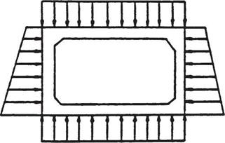
FIGURE 5.38 Pressure distribution used for design of concrete box culverts. (From "Hydraulic Design of Highway Culverts," Hydraulic Design Series No. 5, FHWA, with permission) |
For a complete discussion on the design of concrete pipe, including methods for designing elliptical and arch-shaped pipe, see Standard Practice for Direct Design of Buried Concrete Pipe Using Standard Installations (SIDD), ASCE, 1998; Concrete Pipe Technology Handbook, ACPA, 1994; Concrete Pipe Design Manual, ACPA, 2007; and Standard Specifications for Highway Bridges, AASHTO, 2003.
Structural Design of Boxes and Three-Sided Culverts. The assumed load distribution for reinforced concrete box culverts is shown in Fig. 5.38. The fluid load and structure load are the same as those used for circular concrete pipe (see Art. 5.8.2). The vertical component of the earth load is considered to be the soil prism load. The horizontal component of the earth load is specified by AASHTO such that the structure is designed using both a 30-lb/ft3 (4.8-kN/m3) and 60-lb/ft3 (9.6-kN/m3) lateral earth pressure. The live load is distributed through the soil cover as discussed in Art. 5.8.3. Three-sided structures are designed using similar load theory except the vertical reaction at the base of the structure is confined to the thickness of the leg.
Box culverts can be designed with either fixed or pinned corners. All box culverts with spans greater than about 8 ft (2.4 m) are designed with fixed corners. Three-sided culverts are generally designed with fixed corners exclusively. Those structures designed with pinned corners are designed for simple beam moments, and the lateral earth pressure of 60 lb/ft3 (9.6 kN/m3) is the only condition for which the sidewall need be designed. Because fixed corners transfer moments around the corners, applying the 60-lb/ft3 (9.6-kN/m3) lateral pressure will reduce the positive moments in the adjacent members when compared with the application of 30 lb/ft3 (4.8 kN/m3). For this reason, structures with fixed corners must be designed for both lateral load conditions to ensure that all maximum moments in each member are found. Table 5.17 indicates the loading conditions that generally control the design of the top slab and side walls of concrete box culverts for moment and shear. After determining maximum moments and shears, the designer may utilize standard principles of reinforced concrete design to size the members and calculate the necessary reinforcement.
As is evident from the foregoing, and is true for any structural design, many different loading conditions must be investigated to ensure the maximum stresses are determined. To reduce design time, the FHWA has developed the computer program BOXCAR,
 |
which may be used for the structural analysis and design of reinforced concrete box culverts.
Structural Design of Cast-in-Place Pipe. Because cast-in-place concrete pipe has no reinforcement, its flexural strength is limited. In this type of structure, the effects of the compression on the member keep the effects of the moment below the modulus of rupture of the concrete, and no reinforcing is necessary. Also, because it is cast against the ground at the invert and walls, it has excellent bedding conditions, and this contributes to a reduction in moments, thrusts, and shears.
The moments, thrust, and shears can be calculated using the uniform load system developed by J. M. Paris. This system provides a method for determining maximum stresses through the application of nondimensional load coefficients, similar to the direct design of concrete pipe. As indicated in Fig. 5.39 the Cm coefficients are multiplied by the load and the mean radius to obtain the moment, and the Cv and Cn coefficients are multiplied by the load to obtain shears and thrusts.
Once these have been determined, normal stresses can be calculated from the fundamental equation
![]() _T ± MM ~A ± I
_T ± MM ~A ± I
where fc = concrete stress, lb/in2 (MPa)
T = thrust, lb/in (N/mm)
A = wall area, in2/in (mm2/mm)
M = bending moment, in • lb/in (mm • N/mm) c = distance from neutral axis to extreme fiber, in (mm)
I = moment of inertia of wall, in4/in (mm4/mm)
Because the concrete is unreinforced, the stress may not exceed the modulus of rupture of the concrete adjusted by an appropriate safety factor. The FHWA recommends that the use of cast-in-place pipe on federal-aid highway projects be monitored through experimental projects in locations under roadways or with moderate to high fills.
Structural Design of Special Shapes. Most of the special shape structures are considered soil-structure interaction systems and require complex structural analysis. They are typically analyzed using the finite-element method. Design is then completed using standard principles of reinforced concrete design. The manufacturers’ of these structures maintain a catalog of designs for common size and loading conditions.


Leave a reply