Rigid Pavement Joint Sealing
Joint sealing prohibits the infiltration of water into the pavement base and prevents incompressibles from lodging within the joint cavity. The advantages of keeping water out from under a pavement are documented extensively in the AASHTO Pavement
|
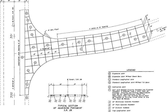
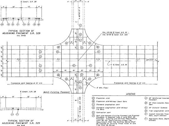
FIGURE 3.4 Layout of joints in rigid pavement at skewed intersection. Conversions: 1 in = 25.4 mm, 1 ft = 0.305 m. |
|
|
|
Design Guide and in various articles in this chapter. With an unsealed joint, contraction under cooler temperatures allows joint cavities to open up and become filled with sand, stone, and other incompressible material. When warmer temperatures try to expand the length of the pavement, the joints are unable to close, compressive stresses develop, and spalling may result.
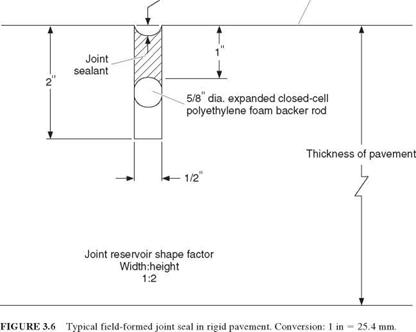
The purpose of a sealant reservoir (Figs. 3.1, 3.2, and 3.6) is to prevent water and incompressibles from entering the joint cavity. The design criteria for the sealant reservoir ensure that the sealant stays in place. The ability of the sealant to expand and contract with the movement of the joint is a function of the material properties of the sealant (defined by the manufacturer’s specifications) and the expected movement of the joint. Joint movement can be calculated using the following relationship:
AL = CL(A AT + Z) (3.3)
where AL = joint opening created by changes in temperature and loss of moisture during curing (joint movement), ft (mm)
C = constant used to adjust for friction between bottom of slab and the material that directly supports the pavement (0.65 for granular material, 0.80 for stabilized material)
L = joint spacing, ft (mm)
A = thermal coefficient of concrete, 10 6/°F (10 6/°C), multiplied by the following factors depending on coarse aggregate type: quartz, 6.6 (11.9); sandstone, 6.5 (11.7); gravel 6.0 (10.8); granite, 5.3 (9.5); basalt, 4.8 (8.6); and limestone 3.8 (6.8)
AT = difference in minimum temperature pavement will be subjected to and temperature at which pavement was placed, °F (°C)
Z = drying shrinkage coefficient of the portland cement concrete (PCC) slab, in/in (mm/mm). The coefficient depends on the indirect tensile strength, lb/in2 (MPa) as follows: 0.0008 for 300 (2.1), 0.0006 for 400 (2.8), 0.00045 for 500 (3.4), 0.0003 for 600 (4.1), 0.0002 for 700 (4.8)
(See “AASHTO Design Procedures for New Pavements,” FHWA Report HI-94-023, ERES Consultants, Inc., February 1994; and FHWA Technical Advisory T 5040.30, November 30, 1990.)
There are two categories of joint sealants. The field-molded sealant and the preformed compression seal are used extensively in rigid pavements. Also, field-molded sealants are gaining acceptance and being used in flexible pavements.
For field-molded sealants, the design is very simple and is controlled by the following relationship:
W = — (3.4)
where AL = joint opening to be accomodated, in (mm)
W = design width of transverse contraction joint, in (mm)
S = allowable strain specified by sealant manufacturer (typically 25 to 50 percent for field-molded sealants)
To control the strain in field-molded sealants, manufacturers recommend a reservoir shape factor (width to depth), and the use of a backer rod as illustrated in Fig. 3.6. The purpose of the backer rod is to prevent bond at the bottom of the sealant reservoir where the actual crack in the pavement exists. It is at this crack that the greatest strain will occur. Typical joint sealants are either asphalt-based or silicone-based.
For preformed compression seals, the uncompressed width of the compression seal should be chosen according to manufacturer’s specifications, as the material response characteristics are of primary importance. The calculated movement of the joint, normalized by the width of the uncompressed seal, should be less than or equal to the allowable movement of the compression seal, as determined by the manufacturer. Figure 3.7 shows a typical preformed seal installed in a pavement joint.


Leave a reply