RIGID PAVEMENT DESIGN PROCEDURE
3.
 |
Determine the drainage coefficient for the pavement.
4. Select the design serviceability loss.
5. Estimate the total number of 18-kip (80-kN) equivalent single-axle loads for the design period.
6. Select a level of reliability and the overall standard deviation.
7. Determine slab thickness and steel reinforcement.
Determine Effective Subgrade Modulus. The first step in designing the thickness of a rigid pavement is the determination of the effective modulus of subgrade reaction. The effective modulus (or composite modulus) is the modulus of subgrade reaction after correction for use of subbase, seasonal variation in subgrade and subbase strength, rigid foundation within 10 ft (3 m) of the surface, and loss of support. Figure 3.11 is used to determine the composite modulus of subgrade reaction when a subbase will be used under the concrete pavement. If the pavement will be placed directly on the subgrade, the AASHTO Pavement Design Guide recommends a composite modulus of subgrade reaction of:
where k is in lb/in3 and MR is in lb/in2.
When a stiff layer (bedrock, etc.) is located within 10 ft (3 m) of the surface, the stiff layer will provide additional support for the pavement. Figure 3.12 is used to correct the composite modulus of subgrade reaction for this additional support.
Example:
DSB = 6 in (150 mm)
ESB = 20,000 lb/in2 (138 MPa)
MR = 7,000 lb/in2 (48 MPa)
Solution: k* = 400 lb/in3 (0.109 N/mm3)
2000 3000 5000
7000
10,000
12,000
16,000
20,000
FIGURE 3.11 Chart for estimating composite modulus of subgrade reaction kra, assuming a semiinfinite subgrade depth; defined as over 10 ft (3 m) below subgrade surface. (From Guide for Design of Pavement Structures, American Association of State Highway and Transportation Officials, Washington, D. C., 1993, with permission)
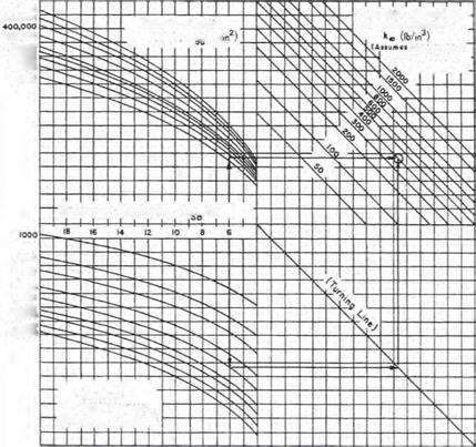 In regions where large moisture variations, freeze and thaw, etc., will affect the strength of the subgrade soils and subgrade, AASHTO provides a procedure to modify the composite modulus of subgrade reaction. Table 3.22 provides a worksheet, and Table 3.23 shows an example. The seasonal variation in strength is determined using laboratory procedures or nondestructive testing (NDT). The seasonal strength of the subbase and subgrade is entered in columns 2 and 3 of Table 3.22. The composite modulus of subgrade reaction is determined using Fig. 3.11 and entered in column 4. If a rigid foundation is present within 10 ft (3 m) of the surface, the k value is corrected
Example:
MR = 4000 Ib/in2 (27.6 MPa)
□SG = 5 ft (1.5 m)
= 230 Ib/in3 (0.062 N/mm3)
![]()
![]()

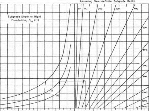 Solution: к = 300 Ib/in3 (0.081 N/mm3)
![]() Modulus of Subgrade Reaction, к (ib/in3)
Modulus of Subgrade Reaction, к (ib/in3)
(modified lo account for presence of rigid foundation near surface)
FIGURE 3.12 Chart for modifying modulus of subgrade reaction to consider effect of rigid foundation near the surface. Conversions: 1 lb/in2 = 6.895 X 10⁻³ MPa, 1 lb/in3 = 271.4 X 10⁻⁴ N/mm2, 1 ft = 0.305 m. (From Guide for Design of Pavement Structures, American Association of State Highway and Transportation Officials, Washington, D. C., 1993, with permission)
Trial subbase: Type _________________ Depth to rigid foundation, ft
Thickness, in___________ Projected slab thickness, in
Loss of support, LS______
|
Month (1) |
Roadbed modulus Mr, lb/in2 (2) |
Subbase modulus, ESb, lb/in2 (3) |
Composite k value, lb/in3 (Fig. 3.11) (4) |
k value, lb/in3 on rigid foundation (Fig. 3.12) (5) |
Relative damage u (Fig. 3.13) (6) |
|
January |
|||||
|
February |
|||||
|
March |
|||||
|
April |
|||||
|
May |
|||||
|
June |
|||||
|
July |
|||||
|
August |
|||||
|
September |
|||||
|
October |
|||||
|
November |
|||||
|
December |
|||||
|
Average: ur = ____ n Summation: = |
Effective modulus of subgrade reaction k (lb/in3) =_________
Corrected for loss of support (Fig. 3.14): k (lb/in3) =________
Conversions: 1 lb/in2 = 6.895 X 10_3 MPa, 1 lb/in3 = 271.4 X 10_4N/mm2, 1 in = 25.4 mm, 1 ft = 0.305 m. Source: Guide for Design of Pavement Structures, American Association of State Highway and
Transportation Officials, Washington, D. C., 1993, with permission.
TABLE 3.23 Example Application of Method for Estimating Effective Modulus of Subgrade Reaction
Trial subbase: Type ____ Grammar_____ Depth to rigid foundations, ft__________ 5
Thickness, in ___________ Projected slab thickness, in ___________ 99
Loss of support, LS І-0
|
Month (1) |
Roadbed modulus Mr, lb/in2 (2) |
Subbase modulus, ESB, lb/in2 (3) |
Composite k value, lb/in3 (Fig – 3-11) (4) |
k value, lb/in3 on rigid foundation (Fig – 3,12) (5) |
Relative damage ur (Fig – 3-13) (6) |
|
January |
20,000 |
50,000 |
1,100 |
1,350 |
0-35 |
|
February |
20,000 |
50,000 |
1,100 |
1,350 |
0-35 |
|
March |
2,500 |
15,000 |
160 |
230 |
0-86 |
|
April |
4,000 |
15,000 |
230 |
300 |
0-78 |
|
May |
4,000 |
15,000 |
230 |
300 |
0-78 |
|
June |
7,000 |
20,000 |
410 |
540 |
0-60 |
|
July |
7,000 |
20,000 |
410 |
540 |
0-60 |
|
August |
7,000 |
20,000 |
410 |
540 |
0-60 |
|
September |
7,000 |
20,000 |
410 |
540 |
0-60 |
|
October |
7,000 |
20,000 |
410 |
540 |
0-60 |
|
November |
4,000 |
15,000 |
230 |
300 |
0-78 |
|
December |
20,000 |
50,000 |
1,100 |
1,350 |
0-35 |
|
Summation: Xu = 7-25 |
|
Average: йг = X r =____ °-60________ r n |
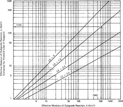
Effective modulus of subgrade reaction k (lb/in3) = 540 Corrected for loss of support (Fig – 3-14): k (lb/in3) = 170
Conversions: See Table 3-22-
Source: Guide for Design of Pavement Structures, American Association of State Highway and
Transportation Officials, Washington, D-C-, 1993, with permission-
|
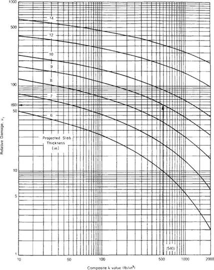
FIGURE 3.13 Chart for estimating relative damage to rigid pavements based on slab thickness and underlying support. Conversions: 1 lb/in3 = 271.4 X 10_4 N/mm2, 1 in = 25.4 m. (From Guide for Design of Pavement Structures, American Association of State Highway and Transportation Officials, Washington, D. C., 1993, with permission) |
using Fig. 3.12 and entered in column 5. The corrected k value is then used in Fig. 3.13 to determine the seasonal or relative damage factor, which is entered in column 6. The sum of relative damage is divided by the total number of periods to determine the average relative damage factor. This value is entered in Fig. 3.13 to determine the average composite modulus of subgrade reaction for the year. Many concrete pavements fail as a result of pumping or loss of support under the slab. Figure 3.14 is provided to correct the effective modulus of subgrade reaction for loss of support. This figure lowers the k so that the
|
FIGURE 3.14 Chart for correction of effective modulus of subgrade reaction for potential loss of subbase support. Conversion: 1 lb/in3 = 271.4 X 10~4 N/mm2. (From Guide for Design of Pavement Structures, American Association of State Highway and Transportation Officials, Washington, D. C., 1993, with permission) |
stress in the slab will be the same as for a slab with a void. Although the AASHTO procedure includes design for loss of support, it is recommended that a pavement base be designed to prevent or reduce loss of support, especially under pavements supporting a large number of heavy loads in wet areas. The cost of providing a base to resist loss of support may be less than the cost of restoring support in the future.
Select Pavement Material Properties. The next step in the design of a rigid pavement is to select material properties. The reliability level and overall standard deviation consider the variation in material properties. Therefore, average material property values must be used in design. The concrete material values needed for design are the average concrete modulus of elasticity and the average concrete modulus of rupture. These values are not known until after construction of the pavement unless the plans for the pavement contain a performance specification. Material properties from past pavement construction may be used for design purposes provided a similar mix will be used. American Society for Testing and Materials’ “Test Method for Static Modulus of Elasticity and Poisson’s Ratio of Concrete in Compression,” ASTM C469, details the laboratory test method for determining the concrete modulus of elasticity. ASTM C78,
|
TABLE 3.24 Recommended Values of Drainage Coefficient Cd for Rigid Pavement Design
Source: Guide for Design of Pavement Structures, American Association of State Highway and Transportation Officials, Washington, D. C., 1993, with permission. |
“Test Method for Flexural Strength of Concrete (Using Simple Beam with Third-Point Loading),” details the laboratory test method for determining the concrete flexural strength (modulus of rupture).
Determine Drainage Coefficient. The drainage coefficient is used to modify the design thickness for drainage conditions. Moisture affects the pavement performance by decreasing the strength of the subgrade and subbase material and affects the warping and curling behavior of the concrete slabs. The intent of the drainage coefficient is to allow performance prediction for pavements without a proper drainage system. Increasing the pavement thickness should not be used in lieu of a properly designed drainage system. Recommended values for the drainage coefficient are given in Table 3.24. The Federal Highway Administration’s “Highway Subdrainage Design Manual,” Report No. FHWA-TS-80-224, provides a procedure that may be used to determine drainage times for base material. (See Arts. 5.4.5 and 5.4.6.)
Select Design Serviceability Loss. The design serviceability loss is the amount of serviceability loss the agency will tolerate before rehabilitation. To select a design serviceability loss, the designer needs to know the initial serviceability and the terminal serviceability of the pavement. The initial serviceability is the serviceability immediately after construction. Since this value is unknown at the time of construction, the designer will usually use the average initial serviceability of previously constructed pavements. The terminal serviceability is the serviceability of a pavement immediately before rehabilitation. The terminal serviceability is a function of traffic volume and speed. A low-volume road with low speeds may be allowed to deteriorate to a lower serviceability than a high-volume freeway, since the associated user costs will be lower. The terminal serviceability used by an agency is a policy decision. Common terminal serviceabilities are 2.5 for high-volume roads and 2.0 for low-volume roads.
Estimate ESALs. The daily ESAL loadings are determined as outlined in Art. 3.5.2. The total number of ESAL loadings for design is the cumulative number of ESAL loadings expected over the design life of the pavement. This value can be determined by assuming a growth rate or, if the pavement is being built on an existing alignment, by extrapolating past traffic patterns.
Determine Slab Thickness and Reinforcement. The design slab thickness is determined by using the design values as outlined above in the nomograph shown in Fig. 3.15. The design thickness is usually rounded up to the nearest 1/2 or 1 in (13 or 25 mm) depending on the local practice for specifying slab thickness. As mentioned in Art. 3.5.2, if the design thickness varies significantly from the thickness used to determine the equivalency factors, the equivalency factors should be recalculated and the thickness design checked. Determination of steel reinforcement content, if used, is detailed in Art. 3.1.1.


Leave a reply