Loads
Introduction. Loads acting on buried structures include the dead load of the structure itself, the dead load of the earth cover over the structure, the weight of the fluid within the structure, live loads from vehicles, and, under certain circumstances, external hydrostatic pressure from groundwater.
The structure dead load is only significant for rigid structures. Flexible structures are manufactured from plastic or metal. In each case, the weight of the material is insignificant when compared with the total load on the structure. For rigid structures, however, because the material is generally concrete and because the pipe wall thickness is considerable, the weight of the material should be included in the determination of the total load applied on the structure. For concrete pipe, the pipe weight, Wp, can be estimated using the following equations:
Circular:
![]()
![]()
![]() Wp = 3.3h (Di + h) in U. S. Customary units Wp = 74 X 10-6h (Di + h) for SI units
Wp = 3.3h (Di + h) in U. S. Customary units Wp = 74 X 10-6h (Di + h) for SI units
Arch or horizontal elliptical:
Wp = 2.8h (Si + h) in U. S. Customary units Wp = 63 X 10-6h (Si + h) for SI units
Vertical elliptical:
Wp = 4.2h (Si + h) in U. S. Customary units Wp = 94 X 10-6h (Si + h) for SI units
where Wp = pipe weight, lb/ft (kN/m)
Di = inside pipe diameter, in (mm)
Si = inside horizontal span, in (mm) h = pipe wall thickness, in (mm)
(See Concrete Pipe Technology Handbook, American Concrete Pipe Association, 1994.)
Earth Load. The first detailed studies of the loads on buried pipes were conducted by Anson Marston at the Iowa State University in the early 1990s. These studies resulted in the Marston load theory for rigid pipes. The theory provides a methodology for determining the loads on buried pipes in almost any installation condition.
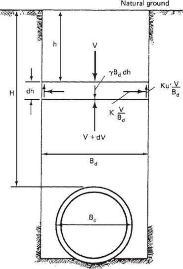
Marston theorized that a pipe in a trench was in static equilibrium. Therefore, the summation of vertical forces was zero. He also concluded that the pipe and backfill would settle relative to the in situ trench walls. He then went about determining the different forces acting on the pipe. Represented pictorially in Fig. 5.31, these are the weight of the soil in the trench, the resisting vertical force at the bottom of the trench, and the shear forces present at the interface of the backfill and the native trench wall.
|
FIGURE 5.31 Forces acting on a buried pipe as presented by Marston. (From Soil Engineering, 4th ed., HarperCollins, 1982, with permission) |
Through a mathematical transformation of the equilibrium equation, Marston arrived at the following equation for a rigid pipe in a trench:
W£ = CdlBl (5.24)
with
![]() Cd =
Cd =
d 2Kp
where WE = earth load, lb/ft (kN/m)
7 = soil unit weight, lb/ft3 (kN/m3)
H = height of cover, ft (m)
Kp! = frictional coefficient
Bd = trench width, ft (m)
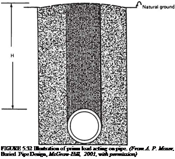
Marston also investigated the loads on rigid pipes in embankment conditions. However, since there are no trench walls, it was necessary to determine the relative movement of the pipe and soil directly above the pipe to the fill material adjacent to the pipe. The soil directly above the pipe is called the soil prism (see Fig. 5.32). This gave a measurement of the shear forces at the interface of the embankment and soil prism. Marston then used similar procedures for determining the loads on pipes in embankments as he used for pipes in trenches. He set the system in static equilibrium and summed vertical forces. Using this procedure, he derived formulas for several embankment installation conditions.
 |
Marston’s student, M. G. Spangler, expanded the previous work of Marston in determining a method for relating the strength of an installed rigid pipe to the strength
of a pipe in a three-edge bearing test. Marston originally introduced the concept of a bedding factor for this purpose. Spangler refined the method by introducing the 0.01-in (2.5-mm) crack as a laboratory performance limit for equating the in-field performance to the three-edge bearing test performance. Later, as use of corrugated metal pipe increased, Spangler noticed that the Marston load theory did not provide satisfactory results for flexible pipes. The load that a flexible pipe was able to support was much greater than what was predicted using Marston load theory and bedding factors. Spangler completed a series of field and laboratory tests to investigate the loads on flexible pipes. His analyses resulted in the now famous Iowa formula, which was subsequently revised by R. K. Watkins.
More recently engineers have attempted, through the use of computers and finite element analysis, to better represent soil-structure interaction and the resultant loads on buried pipes. They have met with varying degrees of success. The works of both Marston and Spangler are still widely used in engineering practice. The calculation of pipe deflection by the Iowa formula is given in Art. 5.8.6. For a complete discussion of the Marston load theory and Spangler’s Iowa formula, see A. P. Moser’s Buried Pipe Design, 2d ed., McGraw-Hill, 2001.
Representations of earth loads are gradually moving away from the use of the Marston loads. In lieu of the Marston loads, the earth load is represented as a proportion of the soil prism load. The soil prism load is the weight of the column of soil directly above the pipe:
where Wc = prism load, lb/ft (kN/m)
у = soil unit weight, lb/ft3 (kN/m3)
H = height of cover, ft (m)
Do = outside pipe diameter, ft (m)
This is depicted graphically in Fig. 5.32. Depending upon the pipe type (stiffness) and the relative quality of the soil envelope, the effective earth load on the pipe may be greater than, equal to, or less than the soil prism load. This modification of the soil prism load is made via an arching factor. Therefore, the total vertical earth load acting on the structure, WE, is
![]() W£ = VAF (Wc)
W£ = VAF (Wc)
where Wc = prism load
VAF = vertical arching factor
Live Load and Impact. Culverts are usually designed for the live load generated by an AASHTO HS 20 truck. The controlling loading for culverts consists of two axles spaced 14 ft (4.3 m) apart, each weighing 32 kip (145 kN), with wheels on the axle spaced 6 ft (1.8 m) apart transversely. The 16-kip (73-kN) wheel load is the same as for an H 20 loading. The live load applied to underground structures under load factor criteria is either a standard HS truck, or a live load lane.
Where the culvert has a span of 20 ft (6.1 m) or greater, it is classified as a bridge and must be investigated for an alternate military loading of two axles 4 ft (1200 mm) apart with each axle weighing 24 kip (107 kN). The live load lane consists of a uniform load applied in conjunction with a concentrated load. The concentrated load is distributed across the design lane of 10 ft (3000 mm), and is the uniform load. Because of this and because of the relatively short spans associated with culverts, the standard HS truck usually controls as the critical loading.
|
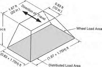
FIGURE 5.33 Distributed load area for single dual wheel. Conversions: 1 in = 25.4 mm, 1 ft = 0.305 m. (From Concrete Pipe Design Manual, American Concrete Pipe Association, 2007, with permission. ) |
Where the fill over a culvert is 2 ft (600 mm) or more, the wheel live load of 16 kip (73 kN) is applied as a concentrated load acting on the wheel print area and uniformly distributed over a rectangle with sides increasing at a rate of 13/4 times the depth of cover. This is represented pictorially in Fig. 5.33. If areas from several concentrated loads overlap, the total load is uniformly distributed over an area as defined by the outside limits of the individual areas.
Rigid structures with less than 2 ft (600 mm) of cover use a different method for distributing the live load. AASHTO code requires that in this case the live load be distributed using the same method as is used in distributing live load in a concrete slab. This method is generally only applied to reinforced concrete box culverts or three-sided culverts.
An impact factor is added to the highway live loading. The factor is equal to 30 percent of the live load for a soil cover of 1 ft (300 mm) or less and decreases to 20 percent for a cover up to 2 ft (600 mm) and to 10 percent for a cover up to 2 ft 11 in (875 mm). There is no impact applied when the cover is equal to or greater than 3 ft (900 mm).


Leave a reply