Length of Need
 |
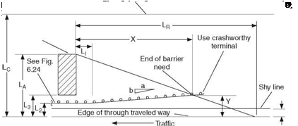
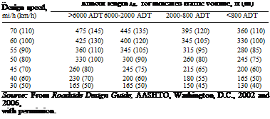
The total length of a longitudinal barrier needed to shield an area of concern is referred to as the length of need. Figure 6.23 illustrates the variables that must be considered, particularly the runout length LR and the lateral extent of the area of concern LA. The runout length is the theoretical distance needed for a vehicle that has left the road to come to a stop, measured as shown. Suggested values are given in Table 6.5 in terms of the traffic volume and the design speed. The lateral extent of the area of concern is the distance from the edge of the traveled way to the far side of the fixed object, or the outside edge of the clear zone LC of an embankment or fixed object that extends past the clear zone. After major variables are established, the length of the barrier will then depend on the tangent length L1, the distance from the traveled way L2, and the flare rate a:b. If a semirigid railing is connected to a rigid barrier, the tangent length should be at least as long as the transition section to reduce pocketing and increase likelihood of redirection. After variables have been selected, the required
 |
length of need X in advance of the area of concern, for essentially straight sections of roadway, can be calculated from
![]() La + (/a)/) – L2
La + (/a)/) – L2
(b/a) + (La/Lr)
The lateral offset Y from the edge of the traveled way to the beginning of the length of need is
R
The amount of rail installed should be a multiple of 12.5 or 25 ft (3.8 or 7.6 m), because metal-beam barriers are furnished in these lengths. A crashworthy end treatment must be added if the end treatment is located within the clear zone or in a location where it is likely to be struck. If the end treatment permits vehicle penetration, it must be extended upstream to preclude a vehicle from penetrating and striking the shielded feature.
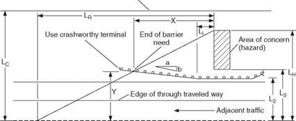
Figure 6.24 shows the definition of variables of an approach barrier for opposing traffic. In this case, lateral dimensions are measured from the edge of the traveled way of the opposing traffic. This would be the centerline for a two-lane roadway or the edge of the driving lane next to the median for a two-way divided roadway. There are three ranges of clear zone width LC to consider for an approach barrier for opposing traffic:
• If the barrier is beyond the clear zone, no additional barrier or crashworthy end treatment is required.
• If the barrier is within the clear zone but the area of concern is beyond it, no additional barrier is required but a crashworthy end treatment should be used.
• If the area of concern extends well beyond the clear zone, consider shielding only that portion which lies within the clear zone (set LA equal to LC).
The lateral placement of the approach rail should satisfy the criterion for embankment slopes. If steeper than 1:10, consider flattening the slope or decreasing the flare rate so the embankment criterion is not violated.
|
Clear distance line for opposing traffic
FIGURE 6.24 Layout of barrier approach. (From Roadside Design Guide, AASHTO, Washington, D. C., 2002 and 2006, with permission) |


Leave a reply