Interchange Elements
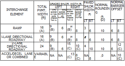
Cross-section information pertaining to interchange elements, such as ramps and directional roadways, is given in Fig. 2.26. This information includes pavement and shoulder dimensions for acceleration-deceleration lanes, one – and two-lane directional roadways, and medians between adjacent ramps. Notice that for a single-lane ramp, the shoulder and guiderail offset distances are greater on the driver’s right-hand side than on the left. This is to provide more width for drivers to pull over in emergencies and to allow people a better opportunity to go around disabled vehicles.
A median is a desirable element on all streets or roads with four or more lanes. The principal functions of a median are to prevent interference of opposing traffic, to provide a recovery area for out-of-control vehicles, to provide areas for emergency stopping and left turn lanes, to minimize headlight glare, and to provide width for future lanes. A median should be highly visible both day and night and in definite contrast to the roadway.
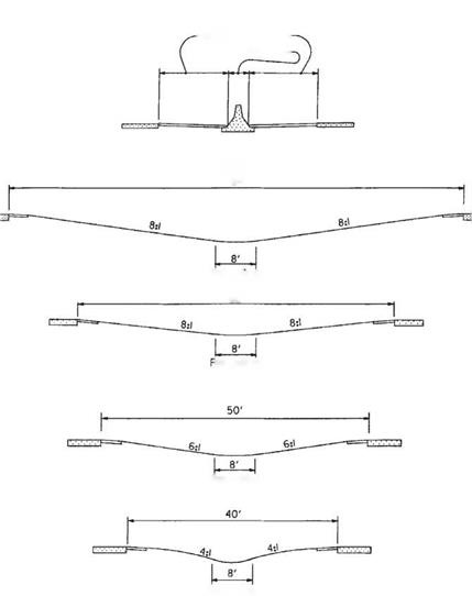
Width. The width of a median is the distance between the inside edges of the pavement. See Fig. 2.27 for examples of various medians. The width depends upon the type of facility, topography, and available right-of-way. In rural areas with flat or rolling terrain, the desirable median width for freeways is 60 to 84 ft (18 to 26 m). Although the minimum median width is normally 40 ft (12 m), narrower medians may be used in rugged terrain. A constant-width median is not necessary, and in fact,
|
|||||||||||||||||||||||||||||||||||||||||||||||||||||||||||||||||||||||||
|
|||||||||||||||||||||||||||||||||||||||||||||||||||||||||||||||||||||||||
|
|||||||||||||||||||||||||||||||||||||||||||||||||||||||||||||||||||||||||
|
|||||||||||||||||||||||||||||||||||||||||||||||||||||||||||||||||||||||||
|
|
||||||||||||||||||||||||||||||||||||||||||||||||||||||||||||||||||||||||
|
|
||||||||||||||||||||||||||||||||||||||||||||||||||||||||||||||||||||||||
|
|||||||||||||||||||||||||||||||||||||||||||||||||||||||||||||||||||||||||
|
|||||||||||||||||||||||||||||||||||||||||||||||||||||||||||||||||||||||||
|
|
|
|
||||||||||||||||||||||||||||||||||||||||||||||||||||||||||||||||||||||
|
|||||||||||||||||||||||||||||||||||||||||||||||||||||||||||||||||||||||||
|
|
||||||||||||||||||||||||||||||||||||||||||||||||||||||||||||||||||||||||
|
|||||||||||||||||||||||||||||||||||||||||||||||||||||||||||||||||||||||||
|
|||||||||||||||||||||||||||||||||||||||||||||||||||||||||||||||||||||||||
|
|||||||||||||||||||||||||||||||||||||||||||||||||||||||||||||||||||||||||
|
|||||||||||||||||||||||||||||||||||||||||||||||||||||||||||||||||||||||||
|
|||||||||||||||||||||||||||||||||||||||||||||||||||||||||||||||||||||||||
|
|
||||||||||||||||||||||||||||||||||||||||||||||||||||||||||||||||||||||||
|
|||||||||||||||||||||||||||||||||||||||||||||||||||||||||||||||||||||||||
|
|
||||||||||||||||||||||||||||||||||||||||||||||||||||||||||||||||||||||||
|
|||||||||||||||||||||||||||||||||||||||||||||||||||||||||||||||||||||||||
Conversion: 1 ft = 0.305 m.
"Distance measured from edge of the traveled lane to face of curb or railing if no curb is provided.
^Distance measured from edge of traveled lane to face of walls or abutments and piers.
cTo minimize structure cost, design tolerances for clearances are plus 4 in, minus 0 in. Sign supports and pedestrian structures have a 1 – ft additional clearance. Clearances shown are over paved shoulder as well as pavement width.
dli bridge is considered to be a major structure having a length of 200 ft or more, the width may be reduced, subject to economic studies, but to no less than 4 ft.
eWhere the truck DDHV is 250 or less, may be reduced 2 ft.
/Where the truck DDHV is 250 or less, the right shoulder width may be reduced 2 ft.
AVhere concrete barrier is used on the approach slabs or in advance of the bridge, the preferred shoulder width will equal the minimum shoulder width.
hA 16.5-ft minimum vertical clearance applies to all rural sections and the single designated route in urban areas. On other urban routes, not on the single designated route, the vertical clearance should not be less than 15.5 ft.
‘If 6 or more lanes, provide 12 ft width. Where truck DDHV is 250 or less, the left shoulder bridge width may be reduced by 2 ft.
;If 6 or more lanes, provide 14 ft width. Where the truck DDHV is 250 or less, the left width may be reduced 2 ft.
![]() *In locations with restricted right-of-way, may be reduced to a clearance of 8.0 ft right side, 4.5 ft median side, plus barrier clearance, except where footnote l applies.
*In locations with restricted right-of-way, may be reduced to a clearance of 8.0 ft right side, 4.5 ft median side, plus barrier clearance, except where footnote l applies.
гМау be reduced to a clearance of 2 ft plus barrier clearance on urban streets with restricted right-of-way and a design speed less than 50 mi/h (80 km/h).
mMay be З-ft width if bridge length exceeds 100 ft.
ftMay be З-ft width if turf shoulder is used.
°May be 2-ft width if turf shoulder is used.
?Clear zone width is defined in Art. 6.2.
Source: Location and Design Manual, Vol. 1, Roadway Design, Ohio Department of Transportation, with permission.
(A)
 |
Use 18′ when inside pavement edge radius is less than 200′.
(B) May be reduced Г if the face of the mainline barrier is 2′ from the outside edge of fhe graded shoulder.
(C) Or match mainline dimension if lesser.
(D) Rounding is 4′ when barrier is used. No rounding is required when foreslope is 6:1 or flatter.
TWO-WAY RAMP MEDIAN
Roundi ng
MINIMUM TWO-WAY RAMP MEDIAN
FIGURE 2.26 Cross-section information for interchange elements—pavement, shoulders, and medians. Conversion: 1 ft = 0.305 m. (From Location and Design Manual, Vol. 1, Roadway Design, Ohio Department of Transportation, with permission) variable-width medians and independent profiles may be used for the two roadways. Narrow medians with a barrier (barrier medians) are normally used in urban areas. Under normal design, the median width will vary depending on the width of the barrier and the shoulder width required (Table 2.23).
Types. Medians are divided into types depending upon width and treatment of the median area and drainage arrangement. In general, raised or barrier medians are applicable to urban areas, while wide, depressed medians apply to rural areas. Figure 2.27 shows examples. Medians in rural areas are normally depressed to form a swale in the center and are constructed without curbs. The type of median used in an urban area
 BARRIER MEDIAN
—Shoulder Width – Barrier Width —
DEPRESSED MEDIANS
84′
Rounding
60′
loundlng
Rounding
Rounding
FIGURE 2.27 Typical designs for medians. Conversion: 1 ft = 0.305 m. (From Location and Design Manual, Vol. 1, Roadway Design, Ohio Department of Transportation, with permission) depends on the traffic volume, speed, degree of access, and available right-of-way. On major streets with numerous business drives, a median consisting of an additional lane, striped as a continuous two-way left turn lane, is appropriate. A solid 6-in-high (0.15-m) lane concrete median may be used in low-speed areas (where the design speed is 40 mi/h (64 km/h) or less) and where an all-paved section is desired and a wider median cannot be justified. Barrier medians are normally recommended for urban facilities when the design speed is over 40 mi/h (64 km/h). However, care must be
exercised when barrier medians are used on expressways with unsignalized at-grade intersections because of sight distance limitations and end treatments of the barrier.
U-Turn Median Openings. U-turn median openings may be provided on expressways, freeways, or interstate highways with nonbarrier medians where space permits and there is a need. U-turns may be needed for proper operation of police and emergency vehicles, as well as for equipment engaged in physical maintenance, traffic service, and snow and ice control. U-turn crossings should not be constructed in barrier-type medians. When U-turn median openings are permitted, it is intended they be spaced as close to 3-mi (4.8-km) intervals as possible. Crossings should be located at points approximately 1000 ft (305 m) beyond the end of each interchange speed change lane.
An example of a typical U-turn median opening is shown in Fig. 2.28, which indicates geometric features applicable to crossings located in medians of widths ranging from 40 to 84 ft (12 to 26 m). Turning radius should be modified proportionately for medians of varying widths. Tapers should be 200 ft (61 m) in length for all median widths. The profile grade line should normally be an extension of the cross slope of the shoulder paving, rounded at the lowest point.


Leave a reply