Inlet and Outlet Control
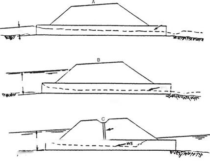
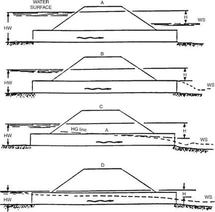
There are two types of flow in culverts: inlet control and outlet control. Accurate prediction of the condition of flow is difficult, and an assumption of the most conservative control may at times be warranted. Figures 5.12 and 5.13 depict several conditions of inlet and outlet control.
For inlet control, the discharge capacity is controlled at the upstream or inlet end. Factors that have an effect on the culvert performance under this condition are the headwater elevation, the inlet area of the barrel, and the inlet configuration. For outlet control, the discharge is controlled at the downstream end. Additional factors affecting performance under this condition include the tailwater elevation, characteristics of the culvert barrel (slope, length, roughness, shape, and cross-sectional area), and the outlet configuration.
With inlet control, the culvert usually flows only partially full; the roughness, slope, length, and outlet condition of the culvert do not affect the discharge capacity. The headwater depth is measured from the invert. The inlet area is generally the same as the cross-sectional area of the barrel. However, when tapered or beveled inlets are utilized, the face area is enlarged and the control area is at the throat. The efficiency of a culvert is greatly affected by the inlet configuration and may be heightened by the use of beveled edges and tapered inlets, which reduce the contraction of the flow, thereby effectively enlarging the face area. Bevels are large chamfers or rounded corners at the inlet. Tapered inlets may be tapered either at the sides or at the bottom (slope tapers). Either type will increase the flow capacity or, conversely, decrease the headwater elevation for a given capacity. Prior to their use, the cost of the improved inlet should be compared with the savings from the use of a smaller barrel.
 INLET SUBMERGED
MEDIAN
DRAIN
HW fv——————————————–
INLET SUBMERGED
FIGURE 5.12 Illustration of culvert under inlet flow control. (From Highway Drainage Guidelines,
Vol. IV, American Association of State Highway and Transportation Officials, Washington, D. C., 1999, with permission)
The coefficient ke, which represents the efficiency of the culvert inlet, is listed in Table 5.9 for many different designs. It may be used to calculate the head loss at the entrance from the equation
where He = entrance head loss, ft (m) ke = energy coefficient V = velocity, ft/s (m/s)
g = acceleration of gravity, 32.2 ft/s2 (9.8 m/s2)
Extensive research by the Bureau of Public Roads and later work by the Federal Highway Administration established a series of equations for determining the headwater at a culvert entrance. In addition, a series of nomographs for the solution of the equations for the various culvert materials were prepared. This information is available in the FHWA publication HDS 5, “Hydraulic Design of Highway Culverts.” The charts in HDS 5 are arranged in groups according to shapes and materials. The charts include the types, materials, and inlet configurations listed below:
1. Circular concrete pipe with both square-edge and groove-edge inlets
2. Circular corrugated metal pipe
|
FIGURE 5.13 Illustration of culvert under outlet flow control. (From Highway Drainage Guidelines, Vol. IV, American Association of State Highway and Transportation Officials, Washington, D. C., 1999, with permission) |
3. Concrete boxes with headwalls or wingwalls, with or without beveled or chamfered inlets
4. Corrugated metal box culverts with earth, concrete, or metal inverts
5. Horizontal and vertical elliptical concrete pipe with both square-edge and groove – edge inlets
6. Corrugated metal pipe-arch
7. Corrugated metal structural plate pipe-arch with 18-in (450-mm) and 30-in (750-mm) corner radii
8. Corrugated metal arch culverts with earth, concrete, or metal inverts
9. Various shapes of structural plate long-span culverts
10. Various shapes of culverts with slope-tapered and side-tapered improved inlets
|
TABLE 5.9 Entrance Loss Coefficients for Culverts under Outlet Control, Flowing Full or Partly Full
*“End section conforming to fill slope,” made of either metal or concrete, is the section commonly available from manufacturers. From limited hydraulic tests it is equivalent in operation to a headwall in both inlet and outlet control. Some end sections, incorporating a closed taper in their design, have a superior hydraulic performance. These latter sections can be designed using the information given for the beveled inlet. Source: From Hydraulic Design of Highway Culverts, HDS 5, FHWA, with permission. |
The charts may also be used for plastic pipes. The appropriate chart selection should be based on a comparative entrance configuration and barrel roughness.
The reader is urged to obtain a copy of this document since it is the primary method used for culvert design and the nomographs it contains are an indispensable design aid.
If a culvert operates under outlet control with a free-water surface along the entire length of the culvert, the nomographs should not be used. In lieu of the nomographs, a backwater calculation should be performed.


Leave a reply