FLEXIBLE PAVEMENT DESIGN PROCEDURE
|
Д (Ib/in2) 4.5- 1.5 |
|
1.624* 107 |
|
18.42 (Ec/k)02 |
|
|
|
|
|
|
![]()
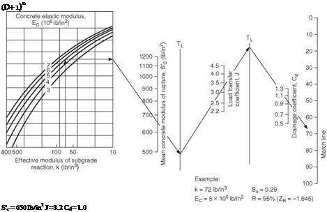
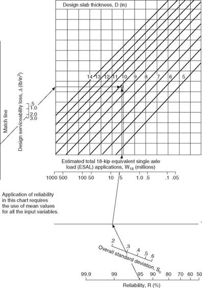
 Д (Ib/in2) = 4.2-2.5= 1.7 W18 = 5.1 x 10⁶ (18-kip ESAL) Solution: D = 10.0 in.
(nearest half-inch, from part b )
FIGURE 3.15 Design chart for rigid pavements based on using mean values for each input variable. Conversions: 1 lb/in2 = 6.895 X 10⁻³ MPa, 1 lb/in3 = 271.4 X 10⁻⁴ N/mm2, 1 in = 25.4 mm. (From Guide for Design of Pavement Structures, American Association of State Highway and Transportation Officials, Washington, D. C., 1993, with permission)
![]()
![]()
![]()
 0
0
10
Note:
|
|
|
|
|
|
|
|
|
|
|
|
|
|
|
|
|
|
|
|
|
|
|
|
|
|
|
|
|
|
|
|
|


 Effective Roadbed Soil Resilient Modulus, M„ (Ib/in >
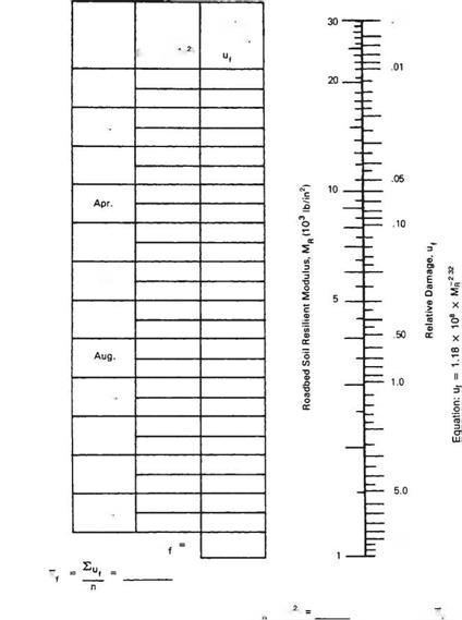
FIGURE 3.16 Chart for estimating effective roadbed soil resilient modulus for flexible pavements designed using the serviceability criteria. Conversion: 1 lb/in2 = 6.895 X 10_3 MPa. (From Guide for Design of Pavement Structures, American Association of State Highway and Transportation Officials, Washington, D. C., 1993, with permission)
Determine Pavement Structural Number. The flexible pavement process involves the calculation of a pavement structural number. This is an abstract number reflecting the relative strength contribution of all layers in the pavement buildup. The structural number SN is calculated using the design values determined as outlined above in the nomograph shown in Fig. 3.17. The design thickness for each layer is determined to satisfy the following equation:
SN = a1D1 + a2D2m2 + a3D3m3
where a1, a2, a3 = structural coefficients of surface, base, and subbase, respectively
D1, D2, D3 = thickness of surface, base, and subbase, respectively, in m2, m3 = drainage coefficients for base and subbase (see Table 3.25)
The structural coefficients of the asphalt layer, granular base, and subbase can be estimated using Figs. 3.18, 3.19, and 3.20, respectively, or can be estimated from Table 3.26.
Select Layer Material and Thickness. Once the structural coefficients are known, the thickness of the individual layers is determined by varying D1, D2, and D3 until the calculated SN is equal to or greater than the required SN. Unbound bases are commonly specified to the nearest 1 in (25 mm), and asphalt concrete is normally specified to the nearest 1/4 in (6 mm). The procedure shown in Fig. 3.21 illustrates one method recommended for determining layer thickness. This procedure designs the upper layers to protect the lower layers.


Leave a reply