Expansion Joint Sealers
Several types of expansion joint-sealing devices are available. Properly sized and installed, they can greatly reduce, if not eliminate, drainage through the joint. Some of the available types are
• Polymer-modified asphalt
• Compression seal
• Slab-type seal
• Strip seal
• Modular seal
Polymer-Modified Asphalt. For resurfacing projects where an asphalt concrete overlay or a portland cement concrete overlay is placed on an existing bridge deck, the approach slab is also overlaid, and the joint movement is moderate (no more than 1.5 in or 38 mm), an expansion joint seal using a poured liquid joint sealer and “armor” of polymer-modified asphalt concrete (elastomeric concrete) can be used. Construction is simple and requires only a minimum of removal of the existing structure, if any. The elastomeric concrete will bond to steel, concrete, or asphalt concrete, and also develop a tenacious bond with the liquid joint sealer, which is poured over backer rod installed between formed vertical faces of the elastomeric concrete. Figure 4.1 illustrates this seal.
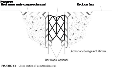
Compression Seal. The compression seal (Fig. 4.2) is a rectangular elastomeric tube that has internal webbing and is manufactured by extrusion. It is installed between formed or sawn faces of concrete, or, more commonly in bridges, between steel armor. A lubricant/adhesive is used to facilitate installation and prevent displacement in service.
|
Cold-applied pourable self-leveling joint sealer
FIGURE 4.1 Cross-section of polymer-modified asphalt concrete joint seal. |
 |
Compression seals can be of the high-compression type, which relies more on internal compression than on the adhesive to stay in place, or the low-compression type, which relies more on the adhesive. The high-compression type is more subject to loss of tight fit due to compression decay with age, and so is less desirable. Catalogs will not describe the seals in this manner, but manufacturers’ representatives will know. A clue to the type of seal is the number of internal webs, which is greater for the high-compression type.
Compression seals are available for joint widths up to 5 in (127 mm), but some agencies impose a 4-in (102-mm) limit. Some skew can be accommodated by using a larger seal than would be required for an unskewed joint. A maximum allowable skew of 15° (with respect to a line normal to the bridge centerline) is imposed by one state. Seals should be one piece for the entire length of the joint.
A variation of the compression seal is a proprietary seal that has no internal webbing. It is installed in the joint by air inflation, which presses the sides against the supporting surfaces, onto which an epoxy adhesive has been applied. The air pressure is released after an adequate curing period, and the adhesive is relied upon to maintain the seal in position.
Slab-Type Seal. The slab-type sealing device consists of an elastomer and internal steel plates that combine to provide a surface that bridges over the joint opening and supports traffic loads. There are notches in the slab that, along with the elasticity of the elastomer, permit it to change length. The sides of the slab are supported on horizontal steel or concrete surfaces, and a bedding adhesive is applied before the slab is fastened down. The slab is fastened to the bridge by closely spaced bolts.
A primary disadvantage of the slab-type seal is that large stresses are induced in the slab by temperature changes, which, along with pounding by traffic, tend to break it loose. Some users of slab-type seals have had satisfactory experience with them, but most users have changed to other types of seals.
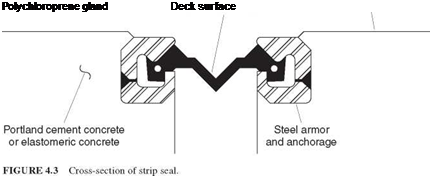
Strip Seal. The strip seal (Fig. 4.3) is an elastomeric extrusion, called a gland, that spans between supporting steel armor. It is anchored by enlargements on the ends of the glands, which are inserted into grooves in the armor. The gland is generally only one layer thick, but some strip seals have two layers, the lower of which should act as a backup if the top layer is punctured. A lubricant/adhesive is used to facilitate installation. Like
 |
the compression seal, the gland should not be spliced. Special tools should be used to install the gland, and the gland should not be stretched during installation. Left by themselves, contractors may try to use inappropriate tools and brute force to install the gland.
Strip seals can accommodate skew somewhat better than compression seals and are favored by agencies for joint openings larger than can be accommodated by compression seals.

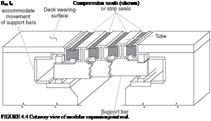
Modular Seal. At the ends of long bridges, or the ends of individual units of long bridges, the joint movement may be greater than can be accommodated by a single joint seal of the types described above. In this case a finger joint with an elastomeric trough may be used, or a modular joint can be provided. The modular joint consists of multiple compression seals or strip seals separated by steel or aluminum structural members, which are in turn supported by bars that span transversely to the joint, parallel to the centerline of the roadway. Figure 4.4 illustrates this type of seal. The support mechanisms can become quite elaborate, with sliding bearings and components to ensure that uniform spacing between longitudinal seal elements is maintained. The designs must provide for joint rotation as well as translation. It is also important that the design of these joints allows for replacement of components.
The fact that many specifiers of sealed expansion joints do not expect them to be, or remain, watertight throughout their life is indicated by the practice recommended for weathering steel bridges (see Art. 4.13). That recommendation is that the steel be painted at the joints, and is applicable to sealed and unsealed joints alike.
Failure of an expansion joint can occur in the sealing mechanism itself, but in the past, failures have occurred as frequently in the anchorages. Some causes of anchorage failure have been
• Inadequate consolidation of concrete below wide legs of armor angles
• Too small or too widely spaced welded stud anchors
• Vulnerability to snowplow damage because the sealing device was not recessed below the wearing surface
• Pressure exerted during thermal changes by overlapping steel angles because the joint design did not properly accommodate longitudinal grade
• Material used to bed or anchor the joint sealing device that was not shrinkage-resistant and broke under traffic


Leave a reply