Energy Equation

The energy equation is based on the principle that energy must be conserved; that is, the energy at any one cross-section on a stream is equivalent to the energy at any other section plus any intervening energy losses. This relationship, a form of the Bernoulli equation, may be used wherever there is a change in the size, shape, or slope of the channel and is useful in determining the depth of flow.
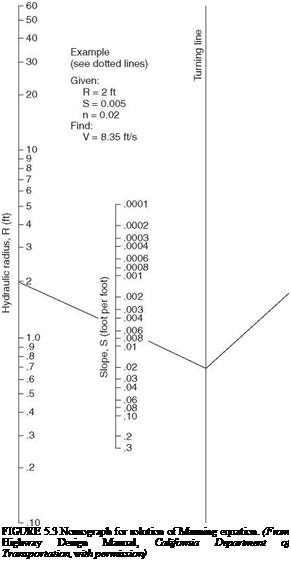
Подпись: FIGURE 5.3 Nomograph for solution of Manning equation. (From Highway Design Manual, California Department of Transportation, with permission)
Energy Equation

/ V2 І V2

z1 + d1 + у j = z2 + d2 + у ^Lg j + hL (5.13)

where zn = distance above some datum, ft (m) dn = depth of flow, ft (m)

Vn = flow velocity, ft/s (m/s) g = acceleration of gravity, 32.2 ft/s2 (9.8 m/s2) hL = head loss between the two sections, ft (m)

TABLE 5.6 Values of the Roughness Coefficient n for Use in the Manning’s Equation

Min

Avg

Max

A. Open-channel flow in closed conduits

1. Corrugated-metal storm drain

0.021

0.024

0.030

2. Cement-mortar surface

0.011

0.013

0.015

3. Concrete (unfinished)

a. Steel form

0.012

0.013

0.014

b. Smooth wood form

0.012

0.014

0.016

c. Rough wood form

0.015

0.017

0.020

B. Lined channels

1. Metal

a. Smooth steel (unpainted)

0.011

0.012

0.014

b. Corrugated

0.021

0.025

0.030

2. Wood

a. Planed, untreated

0.010

0.012

0.014

3. Concrete

a. Float finish

0.013

0.015

0.016

b. Gunite, good section

0.016

0.019

0.023

c. Gunite, wavy section

0.018

0.022

0.025

4. Masonry

a. Cemented rubble

0.017

0.025

0.030

b. Dry rubble

0.023

0.032

0.035

5. Asphalt

a. Smooth

0.013

0.013

b. Rough

0.016

0.016

C. Unlined channels

1. Excavated earth, straight and uniform

a. Clean, after weathering

0.018

0.022

0.025

b. With short grass, few weeds

0.022

0.027

0.033

c. Dense weeds, high as flow depth

0.050

0.080

0.120

d. Dense brush, high stage

0.080

0.100

0.140

2. Dredged earth

a. No vegetation

0.025

0.028

0.033

b. Light brush on banks

0.035

0.050

0.060

3. Rock cuts

a. Smooth and uniform

0.025

0.035

0.040

b. Jagged and irregular

0.035

0.040

0.050

Source: From F. S. Merritt, ed., Standard Handbook for

Civil Engineers,

McGraw-Hill,

2004, with permission.

Subscripts 1 and 2 refer to two sections along the flow line as depicted in Fig. 5.4. The velocity head is given by V2/2g and the specific energy is defined as d + V2/2g. The plots in Fig. 5.4 illustrate the head at points along the length of the channel. The line drawn through points of static head is known as the hydraulic grade line, and the line drawn through points of total head is known as the energy grade line. The head loss between sections includes losses due to flow friction along the channel and losses due to turbulence at junctions and bends.

Updated: 17 ноября, 2015 — 1:17 пп