Drive Profile Design
Drive profiles on uncurbed roadways should slope down and away from the pavement
edge at the same slope as the graded shoulder. Any vertical curve should be developed
|
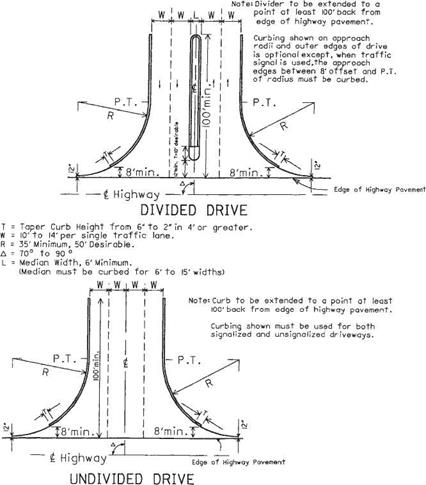
FIGURE 2.57 Designs for shopping center and industrial drives. Conversions: 1 ft = 0.305 m, 1 in = 25.4 mm. (From Location and Design Manual, Vol. 1, Roadway Design, Ohio Department of Transportation, with permission) |
outside the normal graded shoulder width. Vertical curve lengths should be 10 to 20 ft (3.0 to 6.1 m), depending on the grade differential. Under normal circumstances, rural drive grades should not exceed 10 percent, with 8 percent the preferred maximum.
The drive profiles for curbed roadways were developed using the design vehicle described in Fig. 2.50. The profile criterion shown provides clearance for this vehicle when its springs are completely compressed. If conditions of a particular driveway do not meet the cross-section criteria listed below, a template of the design vehicle can be used to design the driveway profile.
For tree lawns 6 ft (1.8 m) or wider, the ramp grade from the gutter to the edge of the sidewalk should be 1 in/ft (8.3%) or less for normal cross-section design. Figure 2.50 shows this condition for the following cross-section conditions:
• Sidewalk and tree lawn slope of /4 in/ft (2.1%) and
• A 6-in (150-mm) curb height with pavement slope of %s or % in/ft (1.6 or 2.1%) or
• Type 2 curb and gutter with pavement slope of %s in/ft (1.6%)
If the cross-section design does not meet the above conditions (has sharper grade breaks), the profile should be designed using a template of the design vehicle.
For tree lawns less than 6 ft (1.8 m) wide, Fig. 2.51 shows the profile treatment. Clearance for the design vehicle is achieved by depressing the sidewalk 1 in (25.4 mm) at the driveway. The sidewalk cross slope of % in/ft (2.1%) is retained. The design may be used directly with curbed highways having cross-section criteria as listed above and the profile conditions of Fig. 2.50. For other cross sections, a template of the design vehicle may be used to design the profile.
Figure 2.51 shows an isometric view and profile for a driveway where only a 3-ft (0.9-m) tree lawn is available. This design is shown not because it is desirable, but because right-of-way width and property development may require this type of design. Whenever feasible, the tree lawn should be 8 ft (2.4 m) or wider. Where the total width of tree lawn and sidewalk is less than 6 ft (1.8 m), the minimum 3-ft (0.9-m) apron designs are inappropriate and cannot be used, as they extend curb or sharp flares into the sidewalk area. For this condition, the sidewalk and curb are transitioned to meet the drive profile as shown on the lower portion of Fig. 2.51. The profile of the drive meets the 1-in (25.4-mm) depressed grade of the sidewalk, as shown in the drive profile.
The tree lawn and walk design shown in Figs. 2.50 and 2.51 will keep storm water, flowing at the curb design height or less, from flowing over the sidewalk. If it is necessary to lower the curb and sidewalk more than 1 in (25 mm), the drainage condition should be checked thoroughly.
Commercial drive profiles usually use a dropped curb across the approach. However, some commercial drives serving large traffic generators may be designed as at-grade intersections, without dropped curbs, because of their high traffic volumes.
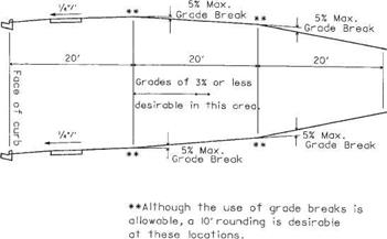
Figure 2.58 shows the recommended grade controls for commercial driveways. The grade should be as flat as possible and still meet drainage requirements. The 20-ft
|
FIGURE 2.58 Profiles for commercial drives. Conversions: 1 ft = 0.305 m, 1/4 in/ft = 21 mm/m. (From Location and Design Manual, Vol. 1, Roadway Design, Ohio Department of Transportation, with permission) |
|
FIGURE 2.59 Commercial design vehicle showing wheel spacings and clearances. Conversions: 1 ft = 0.305 m, 1 in = 25.4 mm. (From Location and Design Manual, Vol. 1, Roadway Design, Ohio Department of Transportation, with permission) |
(6.1-m) length between grade breaks is required by the low clearance and the long axle spacing of the commercial design vehicle shown in Fig. 2.59. Tree lawn profile design should be in accordance with Figs. 2.50 and 2.51. The grade break at the face of the curb is critical for some commercial vehicles, and the cross-section requirements for residential drives on curbed streets should be used.


Leave a reply