Discharge Velocity and Energy Dissipation
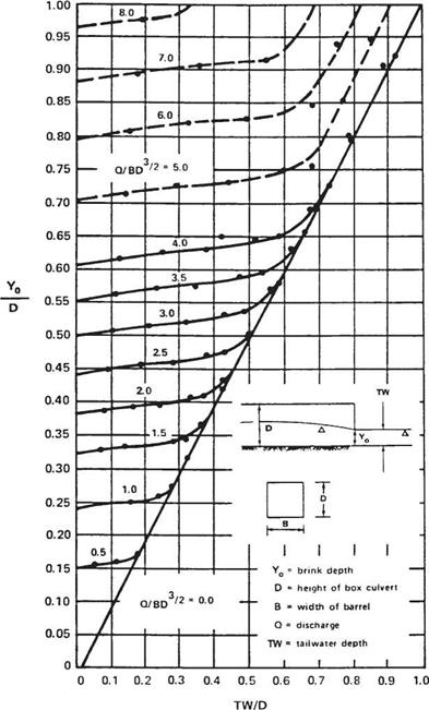
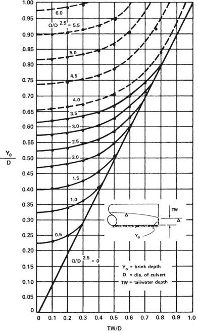
Because of its hydraulic characteristics, the outlet velocity of a culvert is usually higher than the velocity in the discharge channel. The outlet velocity may be calculated either using Manning’s equation, Eq. (5.11), if the culvert is under inlet control, or by dividing the discharge by the cross-sectional area of the flow if under outlet control. Under outlet control, if the tailwater is above the crown of the pipe, or if the discharge is high enough to result in a critical depth equal to the depth of the culvert barrel, then the flow area may be taken as the area of the barrel. If the tailwater depth is low, the area of flow, and thus the velocity, may be determined using the chart in Fig. 5.19 or 5.20. To use these charts, first calculate the normal depth or tailwater TW (ft) in the channel; the ratio TW/D, where D is the structure height (ft); and the flow parameter Q/BD3/2, where B (ft) is the width of the barrel and Q (ft3/s) is the discharge. Enter the chart with TW/D and find YJD at the intersection of the appropriate curve. Multiply by D to determine the depth of flow at the outlet end of the culvert, Yo. The flow area is then calculated for Yo and the velocity for the flow Q from the continuity equation, Eq. (5.10). o
Recommended maximum channel velocities were presented in Table 5.5. The velocity at the outlet should be kept at or below these values, or, if this is not possible, the channel should be protected from erosion. The controlling parameters for the culvert velocity are its slope and roughness. If the recommended velocity is exceeded, consider decreasing the slope or using a culvert with a greater roughness coefficient.
|
|
|
|
If the velocity at the outlet cannot be reduced by these means, channel protection or energy dissipaters should be used to protect against erosion. Channel protection may consist of treatments such as concrete aprons or cutoff walls. In some cases, concrete or rock riprap may be required. These types of protection do not necessarily dissipate the energy, but protect against erosion. Energy-dissipating devices may be necessary either separately or in conjunction with channel protection where flow velocities are high. Dissipation devices, if used, are generally located at the outlet end or in the interior near the end of the culvert. If such devices are used, consideration must be given to the effects on possible debris collection. (See “Hydraulic Design of Energy Dissipators for Culverts and Channels,” HEC 14, FHWA.)


Leave a reply