CULVERT TYPES AND MATERIALS
The main types of pipe used in highway construction are concrete pipe, metal pipe (steel or aluminum), and plastic pipe (high-density polyethylene and polyvinyl chloride). They are available in a wide array of sizes, shapes, and properties. Table 5.10 gives the ASTM and AASHTO standards for the most common highway drainage pipes. Some of the characteristics of these pipes are reviewed below.
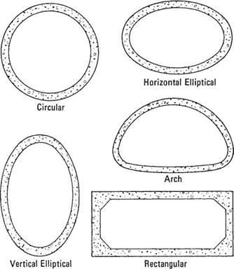
Concrete pipe is manufactured as nonreinforced, reinforced, or cast-in-place pipe; as box culverts and special shapes; and as field-constructed pipe. Shapes, as shown in Fig. 5.21, include round, horizontal and vertical ellipse, and arch configuration.
Factory-Made Pipe. Nonreinforced pipe is used for smaller diameters, whereas pipe with steel reinforcement is used for larger diameters and greater loads. Both are manufactured in a plant, cured, and shipped to the job site. They are furnished in relatively short lengths and coupled with a bell-and-spigot or tongue-and-groove type joint.
Nonreinforced concrete pipe is available in diameters from 4 to 36 in (100 to 900 mm) and three strength classes. Nonreinforced concrete pipe is available as round pipe only. Reinforced concrete pipe is available in diameters from 12 to 144 in (300 to 3600 mm). The strength of reinforced concrete pipe can be specified according to five standard pipe classes (ASTM C 76), with Class I pipe being the most economical and Class V offering the greatest structural strength; according to required D-load strength (ASTM C 655); or according to a direct wall design (ASTM C 1417). Wall thickness of reinforced concrete pipe can be varied to meet in-field conditions. The standard “class” specifications for pipe give wall thickness according to three distinct types, which vary from Wall A, being the thinnest, to Wall C, being the thickest.
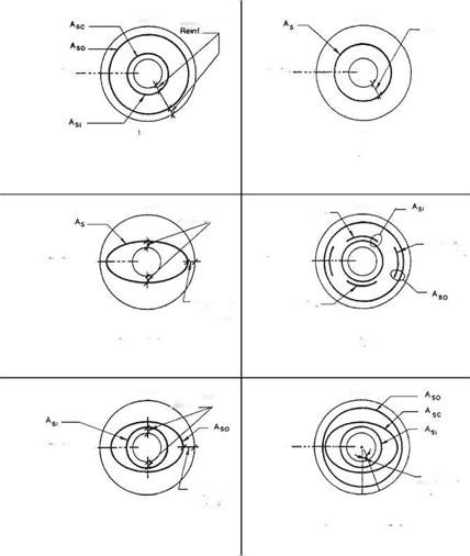
Steel reinforcing for reinforced concrete pipe can be arranged in many combinations to meet the given structural requirements. Figure 5.22 shows some of the steel reinforcement layouts used in manufacturing reinforced concrete pipe.
Cast-in-Place Pipe. This type of nonreinforced pipe is formed in a trench using a continuous process. First a trench is excavated so that it has a semicircular bottom and vertical or near vertical sidewalls, which serve as the outer form for the bottom and sides. The upper portion of the pipe is cast against an inner arch form as illustrated in Fig. 5.23. The form is pulled along the trench while concrete is poured into a hopper
|
TABLE 5.10 Standards for Common Drainage Pipes
|
located above. Powered spading mechanisms and variable-speed vibrators aid the flow of the concrete.
Box Culverts. Box culverts are rectangular shapes with flat sides, top, and bottom. These shapes are constructed with steel reinforcement. Factory-made boxes are shipped in sections 4 to 8 ft (1200 to 2400 mm) long and joined in the field to make a structure of the required length.
Precast Three-Sided Culverts. Three-sided culverts, sometimes called “three-sided box culverts,” are rectangular in shape. These shapes are constructed with steel reinforcement
|
FIGURE 5.21 Concrete pipe is manufactured in five common shapes; regional custom and demand usually determine availability. (From Concrete Pipe Handbook, American Concrete Pipe Association, 1988, with permission) |
that may or may not be pretensioned. They are available in spans between 12 and 34 ft (3.7 and 10.4 m), and rises up to 10 ft (3 m). These structures usually have an open bottom and are constructed on concrete footings.
Special Shapes. Other shapes are also manufactured. One example is a reinforced concrete section made up of an arch top and vertical sidewalls. Another example is a reinforced concrete arch that can be fabricated in either one or two piece segments. Both examples are joined in the field to make up the required length. With spans of 12 to 84 ft (3.7 to 25 m) or larger they are suitable as replacement structures for short span bridges. Additionally, segmental tunnel liners can be furnished as precast concrete segments.
Field-Constructed Pipe. Large reinforced structures may be constructed at the job site using appropriate formwork. Large arches and box culverts are often constructed in this manner.

![]()
![]()
 FIGURE 5.22 Concrete pipe culvert reinforcement notation. (From PIPECAR: User and Programmer Reference Manual, FHWA, 1989, with permission)


Leave a reply