Composite Pavement Distress—Visual Rating
Composite pavement deterioration is exhibited in a combination of some flexible pavement distresses and some rigid pavement distresses. The most prominent composite pavement distresses, which were defined under flexible or rigid pavement, are raveling, bleeding, rutting, corrugations, pumping, and various slab distresses.
If a pavement exhibits structural distresses, such as cracking, patching, potholes, faulting, etc., further evaluation may be necessary to identify the cause of the distress, the extent,
and the strength of the existing pavement system and subgrade. Roadways with high traffic volumes, especially those with high truck volumes, should also be evaluated prior to rehabilitation.
Pavement Coring. Without question, the simplest and most reliable method of identifying pavement deterioration is pavement coring. Pavement coring can be used to investigate many different pavement distress factors, from rigid joint deterioration to stripping in asphalt concrete pavement layers. The following are examples of pavement cores taken in various investigations.
Figure 3.41 shows a core of a composite pavement taken at a transverse joint. The core reveals a tight joint with aggregate interlock and little or no deterioration. The asphalt overlay is left intact. However, during the coring operation, the asphalt portion of the core should be inspected for delaminations between paving layers, rutting of any layers, or stripping of the asphalt from the aggregate.
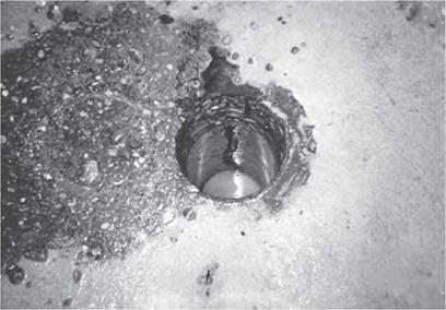
Figure 3.42 shows a core hole in the pavement taken at a midpanel transverse crack. A wealth of information can be obtained by inspection of the core hole. The core hole reveals aggregate interlock to be questionable. A close inspection revealed the reinforcing mesh to be rusted and broken, not cut by the coring operation. Because the core hole indicates most of the aggregate interlock is lost, this crack can be considered a working crack and should be repaired.
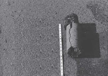
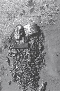
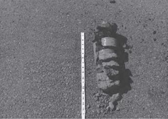
Figures 3.43 and 3.44 show the remains of cores taken at transverse joints. It is obvious that these joints need a full-depth repair. Cores should also be taken away from the joint to determine required width of repair.
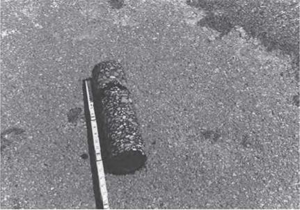
Figure 3.45 shows a core of an asphalt pavement that indicates a delamination approximately 3 in (75 mm) from the surface. Several cores should be taken to verify the extent of the flaw. A delamination found in an asphalt pavement such as this could result in debonding of the surface layer. If warranted, asphalt milling may be required to a depth sufficient to remove the delamination.
|
|
|
FIGURE 3.42 Hole in pavement after core was drilled at transverse crack in composite pavement. |
|
FIGURE 3.43 Crumbled core taken from transverse joint in rigid pavement. |
|
FIGURE 3.44 Crumbled core taken from transverse joint in composite pavement. |
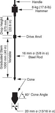
Dynamic Cone Penetrometer. The dynamic cone penetrometer (DCP) is commonly used to determine the stiffness of the base and/or subgrade. As shown in Fig. 3.46, the DCP consists of a 13/16-in (21-mm) diameter, 60° cone mounted on a 5/8-in (16-mm) rod. A 17.6-lb (8-kg) weight is attached to the top of the DCP in such a manner that it can be raised 22.6 in (574 mm) and released while the cone is resting on the base or subgrade.
|
FIGURE 3.45 Core from flexible pavement indicating delamination about 3 in (75 mm) from surface. |
|
FIGURE 3.46 Schematic of dynamic cone penetrometer. (From Pavement Technology Advisory 97-7, Dynamic Cone Penetrometer, Illinois Department of Transportation, Bureau of Materials and Physical Research, 1997, with permission) |
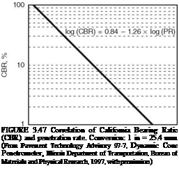
The penetration per drop of the weight is correlated to the CBR or modulus of the base or subgrade. Figure 3.47 shows one such correlation used by the Illinois Department of Transportation. The DCP is popular because it is a relatively inexpensive device that can rapidly determine the stiffness of a base or subgrade in the field.
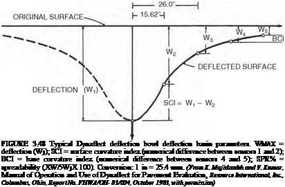
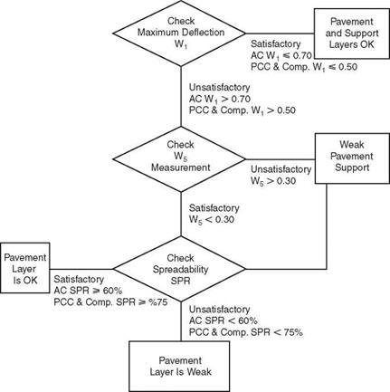
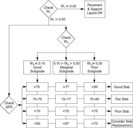
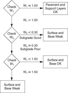
Nondestructive Testing. The most common of the nondestructive testing (NDT) methods is a deflection measuring device such as the falling weight deflectometer (FWD), road rater, and Dynaflect. These devices place a load, either impulse or cyclic, on the pavement and measure the deflection of the pavement using three or more geophones placed at various distances from the load. The measured deflection at each sensor can be described as a “deflection bowl” (see Fig. 3.48). The deflection bowl can be used to evaluate the pavement and to determine the stiffness of the pavement system and individual pavement layers. Stiffness of the layers can be determined using any one of numerous backcalculation programs such as Modulus, Modcomp, Evercalc, etc.; many of which are available in the public domain. The calculated stiffness can then be used to design a rehabilitation treatment. The various deflection parameters shown in Fig. 3.48 can also be used to evaluate the pavement. Table 3.27
0.1 1 10 Penetration Rate, in/blow
 |
— . 49.03” 37.36”
P
and Figs. 3.49 through 3.52 show an example of how the Dynaflect deflections can be used to determine subgrade and pavement conditions.
Ground Penetrating Radar. Improved analysis software has moved the ground penetrating radar (GPR) from research to common usage. This GPR consists of a transmitter
|
|||||||||||
|
|
FIGURE 3.50 Evaluation of rigid and composite pavements from Dynaflect measurements. (From K. Majidzadeh and V. Kumar, Manual of Operation and Use of Dynaflect for Pavement Evaluation, Resource International, Inc., Columbus, Ohio, Report No. FHWA/OH-83/004, October 1983, with permission) |
and receiver. The GPR transmits pulses of electromagnetic energy at various frequencies into the pavement system. The pulses are reflected back to the receiver by the interface of the various pavement layers. The dielectric constant of the various pavement layers is determined by coring the pavement and calibrating the GPR. The GPR can be used to determine pavement layer thicknesses, locate voids, and locate areas with high moisture. Use of the GPR has been standardized in ASTM D-4748.
Spectral Analysis of Surface Waves. Spectral analysis of surface waves (SASW) is currently a research tool but may find use as an evaluation tool in the near future. As shown in Fig. 3.53, two or more accelerometers are attached to the pavement in line with the test point. An instrumented hammer is used to generate surface waves. The accelerometers measure the travel time of the surface waves. By varying the distance between two accelerometers or by using multiple accelerometers, data can be gathered for the deeper pavement layers. Analysis of the surface waves can be used to determine the modulus and thickness of each layer in the pavement surface.
|
FIGURE 3.51 Evaluation of thin (thickness 4 to 6 in) asphalt pavements from Dynaflect measurements. (From K. Majidzadeh and V. Kumar, Manual of Operation and Use of Dynaflect for Pavement Evaluation, Resource International, Inc., Columbus, Ohio, Report No. FHWA/OH-83/004, October 1983, with permission) |


Leave a reply