BRIDGE BEARINGS
For concrete-slab bridges where expansion is not provided, the slab is normally supported directly on the substructure, concrete on concrete. A “centerline of bearing (singular)” is denoted on plans at each support. (Some states do not identify a centerline of bearing at the end bent of a slab bridge. Instead, they measure the end span to the end of the slab.)
In other types of bridges, individual bearings are used to support the superstructure. The centerline of these devices is denoted as the “centerline of bearings (plural).” AASHTO requires that steel bridges with spans of 50 ft (15 m) or greater have a type of bearing employing a hinge, curved bearing plates, elastomeric pads, or pin arrangements for deflection (rotation) purposes. (This specification does not distinguish between simple and continuous spans. Presumably, it was written for simple spans, and so it would make sense that a span greater than 50 ft (15 m) be allowed for pier bearings not providing for rotation when spans are continuous.)
Bearings consist of some or all of the following components:
• Masonry plate resting on the substructure bridge seat
• Rotation device
• Sliding device
• Movement-restraining devices, or “keepers”
• Sole plate attached to the superstructure
Bearings may be fixed bearings, providing for rotation only and preventing differential movement between superstructure and substructure, or expansion bearings. Sliding expansion bearings have a finite capacity depending on the length of the contact surface, or may employ keepers to limit the movement. The range of movement accommodated by the bearing should be greater than the calculated movement.
The type of bearing is typically denoted on the elevation view of the general plan and elevation sheet in the project plans, using “E” for expansion and “F” for fixed.
The main types of bearings are
• Sliding plates
• Rockers and bolsters
• Pins
• Rollers
• Elastomeric bearings
• Disk bearings
• Pot bearings
• Seismic isolation bearings
Sliding Bearings. Sliding bearings will generally have a component made from a material that has a lower coefficient of friction than steel, and that is more corrosion-resistant. Bronze has been used in the past, but has not always maintained sliding capability over the life of the structure. When bearings “freeze,” that is, lose their sliding capability, forces much greater than those anticipated in the design can be exerted on the substructure and ends of beams, doing great damage to both. To reduce friction and prolong the life span of bronze bearings, long-lasting lubrication can be forced under great pressure into trepanned rings on the surface of the bronze. These bearings are known by the brand name Lubrite.
Low friction can be achieved by use of polytetrafluoroethylene (PTFE) sheets mated with stainless steel. This combination is included in many current bearing types to provide for expansion, while other components are used to accommodate rotation. The TFE can be in solid sheet form or woven fabric. During shipping and storage at the job site, the assembly should be banded to prevent dirt from contaminating the sliding
surface. The configuration of the bearing should be such that the sliding surface will not easily become dirty in service.
 |
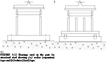
Rockers and Bolsters. Another means of allowing the superstructure to move, without sliding, is by use of rockers. Rockers, as the name implies, permit the superstructure to rock, like a person in a rocking chair, on the substructure. Rockers (Fig. 4.12a) consist of a masonry plate that is bolted to the concrete bridge seat; a rocker element, which is a heavy steel fabrication with a large-radius curved bottom surface and a small-radius semicircular convex pintle on top; and a sole plate, which has a mating concave surface. The height of the rocker is made proportional to the anticipated movement. Within the design range of movement, as the superstructure translates, the rocker tips, but the reaction
to the base plate is maintained within the geometric limits of the rocker, so that the rocker does not tip over. To help prevent the rocker from tipping over, the space between the shoulder of the rocker and the bottom of the sole plate is limited, so that the assembly will bind as its capacity is reached.
Compared with sliding plates, rockers use more massive plates and are therefore less susceptible to severe corrosion and freezing. Because their inclination is readily visible, inspectors can easily determine whether they are functioning properly. Assuming that the rockers were properly installed to be vertical at a given average temperature, one can easily see whether they are inclined excessively or in the wrong direction. In cold weather, when the tops of the rockers should be tipped toward the center of the bridge, an opposite inclination indicates either that unexpected movement of the superstructure has occurred, or that the substructure has moved. Sliding plates can give similar indications, but they require closer observation.
Generally, when rockers are used for expansion bearings, bolsters are used for fixed bearings. The bolster (Fig. 4.12b) is a large steel fabrication consisting of a base plate, which is bolted to the concrete bridge seat; a pintle, which extends upward from the base plate and has at its top a machined convex semicircular shape that fits into a mating concave shape in the sole plate; and reinforcing plates on the sides of the pintle. These side plates are tapered, being wider at the base. This configuration of the mating surfaces allows the beam or girder to rotate, but fixes the superstructure against translation.
Rockers and bolsters, being taller than sliding plates, place the superstructure higher above the substructure. This is desirable for inspection and maintenance, including painting, and in fact is in line with AASHTO requirements that beams, girders, and trusses on masonry be so supported that the bottom flanges or chords will preferably be 6 in minimum above the bridge seat. However, if rockers or bolsters are tall and narrow, they may be aesthetically undesirable for overpass structures, giving the appearance of placing the superstructure on stilts. Because of their susceptibility to seismic loads and other problems, most states have discontinued use of steel bearings of this kind.
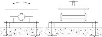
Pins. The pin bearing is used where a fixed condition is desired but rotation needs to be accommodated. As illustrated in Fig. 4.13, it consists simply of a masonry plate, a bottom plate welded to the masonry plate and machined to receive a pin, the pin, and a sole plate that is machined to bear on the pin. The pin is fabricated with shoulders to restrain it laterally within the plates. Clearance is provided between the ends of the plates and the inside faces of the shoulders to allow for lateral expansion of the bridge. For wide bridges, a greater clearance should be provided. A smooth finish is machined onto the pin and the mating surfaces. To prevent corrosion, all parts should be galvanized or metallized. Use of pin bearings, like rockers and bolsters, has widely been discontinued.
|
|
Rollers. For long-span bridges with large reactions, rollers have been used, sometimes in combination with a geared rocker mechanism that is used to transmit the superstructure reaction to the rollers. Several rollers are usually installed in a roller nest, which is a box having (1) a bottom plate, on which the rollers bear, (2) end plates, and (3) substantial side bars by which the relative position of the rollers is maintained. Grease is placed in the box, and a skirt is added to shield the rollers from water and dirt. Unfortunately, the measures taken to prevent corrosion have often not been successful, and the rollers end up being piles of rusted steel, with all expansion capability lost.
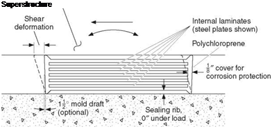
Elastomeric Bearings. The elastomeric bearing, in which superstructure translation can be accommodated by shear, is often the most economical type for both steel and concrete bridges. As shown in Fig. 4.14, this bearing consists of an elastomer such as natural or synthetic rubber (polychloroprene, or neoprene), with or without internal reinforcement, which may be steel plates or glass fiber fabric laminates. A steel-reinforced elastomeric bearing is cast as a unit in a mold and is bonded and vulcanized under heat and pressure; fabric-reinforced elastomeric bearings, popular in California, may be vulcanized in sheets and cut to size. Elastomeric bearings may have external steel load plates bonded to the upper or lower elastomer layer, or both. Natural rubber has better low-temperature properties than neoprene but is not as resistant to surface decay.
 |
In addition to accommodating horizontal movement by deforming in shear, elastomeric bearings can accommodate superstructure rotation. AASHTO design specifications provide methods for properly designing elastomeric bearings, taking into account both translation and rotation requirements. Another desirable attribute of elastomeric bearings is that they can tolerate movements or rotations in directions other than longitudinal. This is not true of sliding plates, rockers and bolsters, and pin bearings. For structures with large skew or curvature, where it is known either qualitatively or quantitatively that such out – of-plane rotations exist, this is a desirable quality. Elastomeric bearings can be fixed bearings (shear prevented), in which case the allowable average compressive stress may be increased 10 percent over that permitted for bearings allowed to deform in shear. Shear is prevented by placing anchor bolts through holes in the bearing, the holes being only slightly larger than the anchor bolts. Steel reinforcement of elastomeric bearings is protected against corrosion by being contained in the elastomer. A minimum cover of 1/8 in is maintained at the edges of the bearing, except at laminate-restraining devices and around holes that are entirely closed in the finished structure.
Under load, elastomeric bearings will undergo a compressive deflection that is determined by the shape factor (loaded plan area divided by the perimeter area free to bulge) and the hardness of the elastomer. Where the dead load compressive strain is significant, allowance should be made for it when establishing bridge seat elevations. The compressibility of elastomeric bearings should also be considered in the design of expansion joints. Joints with overlapping steel elements should be avoided.
A significant shear force can be induced in an elastomeric bearing by movement of the superstructure. This force should be calculated and used in design of the substructure, taking into account also the flexibility of the substructure. For large-movement bearings, a tall and uneconomical elastomeric bearing would be required if the movement were taken entirely by shear. As an alternative, a sliding surface can be combined with an elastomeric bearing so that the bearing initially deforms in shear until the shear force exceeds the frictional resistance of the sliding surface, at which point the bearing slides.
Disk Bearings. Disk bearings are used where rotations occur in different planes. They consist of a polyether urethane disk confined by upper and lower steel bearing plates. Fixed-disk bearings provide for rotations in all directions but do not provide for longitudinal or transverse movements.
To permit expansion, a polytetrafluoroethylene to stainless steel sliding surface is provided above the upper bearing plate. Expansion disk bearings may be guided or nonguided. In a guided bearing, a guide bar or keyway system is used to restrict transverse movement, with the sliding surfaces being PTFE and stainless steel. Nonguided bearings allow rotation and longitudinal and transverse movement.
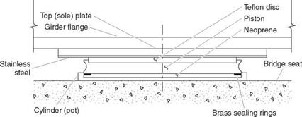
Pot Bearings. Pot bearings, like disk bearings, are used in curved or sharply skewed bridges or other complex structures where rotations occur in different planes. In a pot bearing, the rotational motion is accommodated by compression of elastomeric material in a shallow steel base cylinder, or pot. The load is transmitted to the elastomer through a circular plate or piston, which is part of the upper load plate and which is just slightly smaller in diameter than the inner circumference of the pot. The surface of the elastomeric rotational element is lubricated or has PTFE attached to it to facilitate rotation. Brass sealing rings are used between the steel piston and the elastomeric rotational element to prevent the elastomeric material from being squeezed out. This type of bearing is illustrated in Fig. 4.15. The elements of pot bearings that provide for
|
|
guided or nonguided expansion are like those described for disk bearings. As can be concluded from the discussion of disk and pot bearings, these devices require expensive machining and demand high-quality materials. They are therefore expensive and will not likely be used where other, less costly bearings can serve adequately.
Seismic Isolation Bearings. Sometimes referred to as base isolation bearings, they generally perform two principal functions, namely, motion isolation and restoring, to achieve seismic isolation by shifting the period of the structure or cutting-off the load transmission path to the structure. Lead-core rubber bearings are developed based on the energy-dissipating properties of lead coupled with high-damping properties of elastomer to dampen the seismic forces. In friction pendulum systems, a concave surface allows pendulum motion of the slider or a cylindrical roller of the bearing to lengthen the natural period of the structure to reduce the lateral forces acting on the substructure. Eradiquake™ bearings are another type of friction isolation bearings in which the restoring mechanism consists of cylindrical rubber or MER (mass energy regulator) springs. Springs are positioned in orthogonal directions within the walls of the bearing box and the PTFE/stainless bearing in the center, to help dissipating the energy generated during a seismic event.


Leave a reply