SINGLE-WALL CONSTRUCTION

|
|
|
NON-STRUCTURAL SHEATHING. |
|
|
|
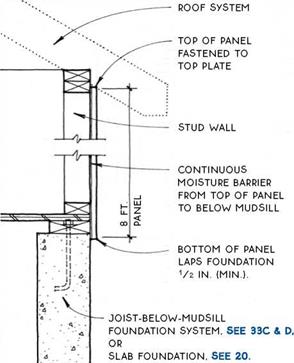
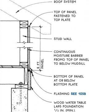
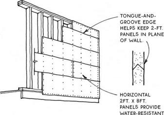
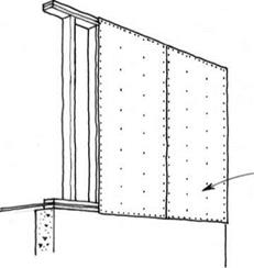
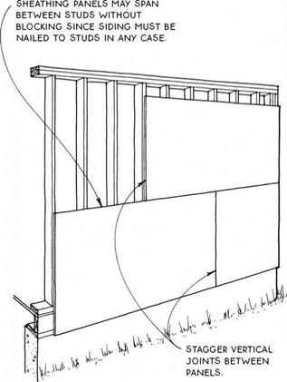
FULL-SIZE PANELS (AFT. X 8FT., 9FT, OR 10FT.) CAN PROVIDE STRUCTURAL sheathing and/or FIRE resistance. |
Many sheet materials that can be used for sheathing do not provide adequate lateral bracing. In addition to providing a base for a moisture barrier and siding, such nonstructural sheathings may also provide insulation or fire protection.
Insulative sheathings range in thickness from V2 in. to 1У2 in. They include fiberboards, foam plastic, and rigid fiberglass boards. R-values vary. Verify that the permeability of the sheathing is coordinated with the permeability of the vapor retarder (see 88A).
Siding must be nailed through nonstructural sheathings directly into the studs beneath them. The need for lateral bracing is often satisfied by applying plywood or other structural panels to the corners of a building, with less-expensive nonstructural sheathing elsewhere.
|
|
Fire-protective sheathings are often required at walls on or near property lines, between attached dwellings, and between garages and living space. Type-X gypsum wallboard applied directly to the studs will satisfy most codes. Water-resistant gypsum board applied to the exterior of framed walls can also serve as an underlayment for various siding materials.
Gypsum board can also satisfy code requirements for shear strength. In this application, 4-ft.-wide panels may be applied vertically or horizontally (if covered with a moisture barrier) and must be nailed at 4 in. o. c. at the 4-ft. ends and 8 in. o. c. elsewhere. The panels do not have to be blocked at edges.
While gypsum sheathing can provide fire protection, water resistance, and structural strength, it has severe limitations for the attachment of siding materials. It is not a nailing base, so any siding material applied over it must be connected through the gypsum to the framing behind or to furring strips or another sheathing material applied over or under the gypsum.
In most cases, minimum code requirements for let-in bracing or structural sheathing will sufficiently stiffen the walls of a light wood-frame building to resist the typical lateral loads of wind or eccentric loading. The stiffened walls act like the sides of a shoe box working in concert with the lid to maintain the overall shape of the box.
In more extreme conditions such as zones with a high risk of earthquakes or severe winds, lateral bracing measures beyond standard structural sheathing or let-in bracing must be taken. For small simple buildings in these zones, codes typically require increased nailing, strapping, and anchoring, as well as extra framing members.
But it is common to have conditions where even these increased code requirements are not adequate. Such conditions generally involve a building in which numerous wall openings reduce the ability of the wall to resist the lateral forces. In these cases, more extreme measures must be taken to resist lateral loads, and these usually involve calculations by an engineer to design diaphragms coupled with shear walls.
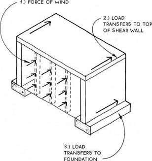
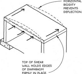
The following diagram summarizes how diaphragms and shear walls work together to resist lateral forces. For simplicity, the diagram shows a wind acting in a single direction perpendicular to the building wall, but in reality, the direction of lateral forces cannot be pre-
|
|
dicted, so lateral resisting systems must be designed for the eventuality of forces in all directions.
The lateral force follows a continuous path through the structure: (1) the force of wind on the windward wall is transferred through studs to the top (and base) of the wall, (2) the diaphragm collects the loads from the top of the windward wall and transfers them to the top of the shear walls at either side, and (3) the shear walls at opposite ends of the diaphragm transfer the loads down to the foundation.
The diagrams on these pages use wind forces to illustrate how lateral forces follow a continuous path through diaphragm and shear walls. Although these structural elements are designed essentially the same to resist the forces of wind or earthquakes, these two forces act differently on buildings. Simply stated, wind forces act on the top of a building and earthquake forces act on the bottom. The relatively light weight of wood-frame buildings works to their advantage in the case of earthquakes, but works against them in the case of high winds.
Diaphragm—A diaphragm is a horizontal structure such as a floor or roof composed of sheathing, framing members, and a structural perimeter. In the case of a floor, the framing members are joists, and the structural perimeter is composed of rim joists and/or blocking (see 32). In the case of a roof, the framing members are common rafters (or trusses), and the structural perimeter is composed of end rafters (or trusses) and frieze blocks (see 129). A diaphragm acts as a horizontal beam to collect lateral forces and transfer these forces to the shear walls.
|
|
Shear walls—Shear walls are extremely strong framed walls that connect the horizontal diaphragm to the foundation. They act like regular braced or structurally sheathed walls to resist the action of lateral forces except that they are much stronger. Their greater strength comes from increased nailing, thicker sheathing, more framing members at their edges, and more substantial anchoring.
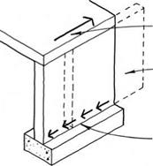
Shear walls act as beams cantilevered from the foundation (or upper floor) to resist forces parallel to them. They are connected at their base to the foundation (or to another shear wall) and at their top to a diaphragm.
At their base, shear walls must resist both sliding and overturning. Horizontal forces can slide the wall off the foundation if adequate shear connections are not provided. Sliding forces are resisted by anchor bolts, by nailing, and/or by framing anchors at upper floors (see 85).
|
|
|
LATERAL FORCES FROM DIAPHRAGM |
|
DEFLECTED SHAPE |
|
ANCHOR BOLTS, FRAMING ANCHORS, AND/OR NAILING PREVENT SLIDING |
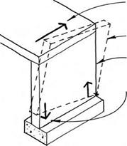
Horizontal forces applied to the top of a shear wall can cause overturning unless the bottom corners are adequately tied (with hold-downs) to resist uplift (see 85 & 86A). While the force is applied, one edge
|
|
|
LATERAL FORCES FROM DIAPHRAGM |
|
DEFLECTED SHAPE LEEWARD EDGE UNDER COMPRESSION |
|
HOLD-DOWN ANCHOI TO FOUNDATION COUNTERACTS TENSION ON WINDWARD EDGE TO PREVENT OVERTURNING. |
of the wall will be in tension while the opposite edge is in compression.
Longer shear walls are inherently better because they have a longer base to resist sliding and because the hold-downs are farther apart to resist overturning.
Connections—Because shear walls involve a large number and variety of components and connections, it is critical that each connection be designed and constructed to resist the forces that pass through it. Depending on their location, connections may be called upon to resist vertical and horizontal forces in several directions. When designing and building to resist extreme conditions, it is especially important to pay close attention to manufacturers’ instructions for the installation of connectors. A shear wall is only as strong as its weakest connection.
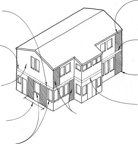
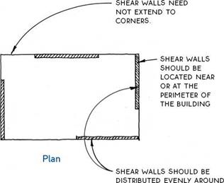
Distribution—Shear walls are generally located within each (principal) exterior wall of a building, but may also be located strategically at interior walls. For earthquake resistance, shear walls should generally be balanced on all four sides of the building; for wind resistance, however, shear walls should be longer (or stronger, see 85B) at the short walls in order to resist the larger wind forces imposed on the long walls.
|
THE BUILDING’S PERIMETER. |
SHEAR WALLS CONNECT TO FLOOR DIAPHRAGM. SEE 86B
![]()

![]()


 DRAG strut TIEs
shear wall TO diaphragm.
SEE 87b
LARGE WALLS On upper levels MAY uSE STANDARD
code-prescribed
SHEATHING TO provide LATERAL RESISTANCE.
Because lateral forces such as wind are assumed to act perpendicularly to the walls of a building, they can theoretically be resisted by shear walls in each of the four walls of a simple building. Forces acting in a north-south direction, for example, can be resisted by shear walls located in the east and west walls of the building (and vice versa). When the wind blows on a diagonal (as it usually does), shear walls in all four walls will be in play.
Because they connect diaphragm to the foundation, shear walls cannot be placed where there are openings in the wall. Therefore, in walls with many openings, there may need to be several shear wall segments in order to provide ample resistance to lateral forces.
Shear walls are most effective when they are wide relative to their height and their base anchors are far
apart. For this reason, codes have specified that shear walls must have a height-to-width ratio of 3.5:1 or less. The practical effect of this limitation is a minimum shear wall width of approximately 2 ft. for a wall 8 ft. tall.
In a building with more than one floor, the need for shear walls is greater on floors nearest the ground. This is because the lower floors are required to resist the forces from upper floors in addition to their own. It is not unusual to have a two-stoiy wood-frame building with engineered shear walls on the ground floor and standard code-prescribed sheathing on the upper floor.
The calculation of shear wall values is fairly complicated—involving different factors for earthquake or wind forces—and is thus usually performed by a licensed engineer.
|
|
|
|
|
|
|
|
|
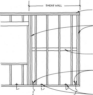
(g) COMPONENTS OF A SHEAR WALL

Once the lateral forces have been determined, there are seven basic considerations that need to be taken into account when designing a shear wall:
Proportion— Most codes specify a maximum height-to-width ratio of 3.5:1. This generally means that shear walls cannot be less than 2 ft. wide.
Hold-downs— Extreme forces at the lower corners of shear walls necessitate metal holddowns to connect the shear-wall chord to the foundation or to lower shear walls (see 85A & 86A). There are a variety of types and capacities of hold-downs.
Anchor bolts— To prevent sliding, anchor bolts are used to connect the base of a shear wall to the foundation. At framed floors, framing anchors and nailing are used to prevent sliding. Hold-downs also resist sliding but are not generally considered in engineering calculations.
Sheathing Strength – The strength of the rated sheathing must match the required capacity of the shear wall. Sheathing on both sides of the shear wall will double its capacity. All panel edges must be blocked to prevent buckling of the panel.
Chord Strength—At the boundaries of the shear wall where stress is greatest, chords must be stronger than standard studs. A minimum of two studs is required by most codes (see 85A).
Strut Strength— Like chords, stmts are at the boundary of shear walls where stresses are greatest. Typical framing (i. e., single sole plate and double top plate) is usually sufficient as struts. Splices in struts should be avoided if possible.
Nailing—Size and spacing of nails must be specified. More nailing is required at the edges of panels than in the field of the panel. Increased nailing acts to increase wall strength (see 78A).


Leave a reply