FOUNDATION & STORM DRAINAGE

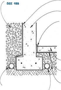
Drainage is essential in protecting a basement from groundwater, but waterproofing the basement wall from the outside is also vital. In selecting a waterproofing material, consider the method of application, the elasticity, and the cost. Below are common waterproofing and drainage materials.
Bituminous coatings—Tar or asphalt can be rolled, sprayed, troweled, or brushed on a dry surface. Often applied over a troweled-on coating of cement plaster that is called parging, some bituminous coatings may be fiberglass reinforced. They have minimal elasticity, and thin coats may not be impervious to standing water.
Modified portland-cement plaster—Plaster with water-repellent admixtures can look exactly like stucco. It is usually applied with a brush or a trowel to a moistened surface. It is inelastic, and unlike parging, it is waterproof.
Bentonite—A natural clay that swells when moistened to become impervious to water, bentonite is available as panels, in rolls, or in spray-on form. It is applied to a dry surface, and is extremely elastic.
Membranes—Rubberized or plastic membranes that are mechanically applied or bonded to a moist or dry surface are moderately elastic.
Bitumen-modified urethane—The most recent development in waterproof coatings, bitumen-modified urethane is applied with a brush to a dry surface. It is elastic, protecting cracks up to Vs in.
Plastic air-gap materials—These drainage materials create a physical gap between the basement wall and the soil. A filter fabric incorporated in the material allows water to enter the gap and drop to the bottom of the wall. These systems are expensive, but they eliminate the need for gravel backfill.
Although waterproofing and drainage will prevent water from entering the basement, water vapor may migrate into the basement through the footing and basement wall. It’s important not to trap this vapor in an insulated wall, so a vapor barrier on the warm side of a basement wall is not recommended. More common and more practical is to allow the vapor to enter the space, and to remove the vapor with ventilation or a dehumidifier.
|
|
||
|
|||
|
|||
|
|
|||
|
|||
|
|||
|
|
|||
|
|
|||

![]()
 NOTES
NOTES
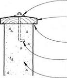
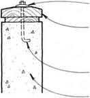
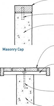
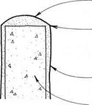
THESE DETAILS ARE FOR THE TOPS OF RETAINING WALLS, WHicH ARE uSuALLY ExPOSED TO THE WEATHER. WOOD caps WILL ultimately decay, SO THEY ARE DESIGNED FOR RELATivE EASE OF REPLAcEMENT. THERE IS NOT MucH POINT IN MOiSTuRE BARRIERS, SiNcE THEY WILL ONLY TRAP RAINWATER AGAINST THE WOOD. RETAINING – WALL SuRFAcES SHOuLD BE PROTECTED FROM MOiSTuRE PENETRATION TO PREvENT DAMAGE FROM THE FREEZE – THAW cYcLE. SEAL WITH cLEAR AcRYLic OR SILicONE, OR WATERPROOF WITH MODIFIED PORTLAND-cEMENT PLASTER
or bitumen-modified urethane.
SEE 180
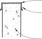
![]() continuous metal cap with drip edge
continuous metal cap with drip edge
FASTEN METAL cAP TO WALL AT SIDE TO
prevent moisture
PENETRATION OF TOP FLAT SuRFAcE.
concrete-block OR concrete wall
@ CONCRETE & CONCRETE-BLOCK WALL CAPS
![]()
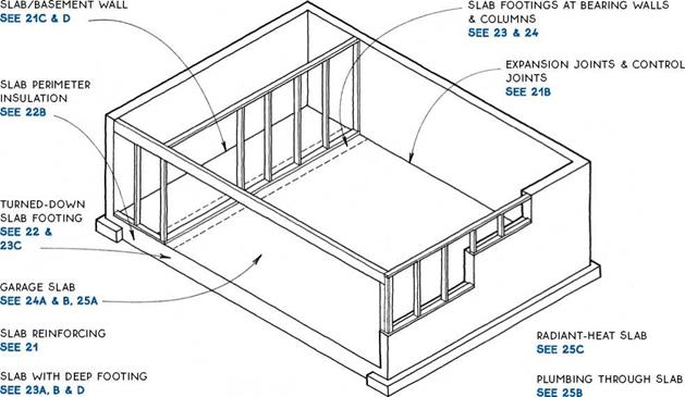
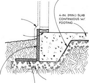
Preparation before pouring a slab is critical to the quality of the slab itself. The primary goals in preparing for a slab are to provide adequate and even support, and to control ground moisture.
Soil—Soil is the ultimate support of the slab. Soil must be solid and free of organic material. Some soils require compaction. In termite areas, the soil is often treated chemically. Verify compaction and soil treatment practices in your local area.
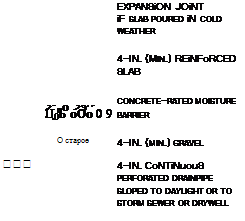
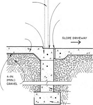
Gravel—Gravel is a leveling device that provides a porous layer for groundwater to drain away from the slab. A minimum of 4 in. of gravel is recommended. Gravel must be clean and free from organic matter. Crushed and ungraded gravels must be compacted. Graded gravels such as pea gravel composed entirely of similar-sized round particles cannot and need not be compacted.
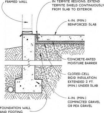
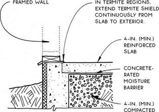
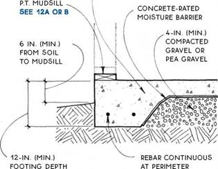
Moisture barrier—Moisture barriers prevent moisture (and retard vapor) from moving upward into a slab. Six-mil polyethylene is common and works well in Detail A. Overlap joints 12 in. and tape the joints in
SLABS
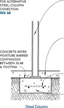
areas of extreme moisture. A more substantial concrete-rated moisture barrier is necessary for Detail B because the moisture barrier is in direct contact with the concrete slab. Polyethylene may deteriorate within
|
CONCRETE SLAB ‘ ~ …___ ^ A A. . ‘ 4 . • C.
|
a very short period in this situation, and it is easily punctured during slab preparation and pouring. A more substantial concrete-rated barrier is a fiber – reinforced bituminous membrane, sandwiched between two layers of polyethylene.
Sand—Sand (shown only in Detail A), allows water to escape from concrete in a downward direction during curing. This produces a stronger slab. The American Concrete Institute recommends a 2-in. layer of sand below slabs.
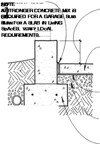
Welded wire mesh—Welded wire mesh (WWM) is the most common reinforcement for light-duty slabs. The most common size is 6×6 (w1.4 x w1.4)—adequate for a residential garage, which requires a stronger slab than a house. One disadvantage to WWM is that the 6-in. grid is often stepped on and forced to the bottom of the slab as the concrete is poured.
Rebar—Rebar is stronger than welded wire mesh.
A grid of #3 rebar at 24 in. o. c is also adequate for a residential garage.
Fiber reinforcement—Fiber reinforcement is a recent development in slab reinforcement. Polypropylene fiber reinforcement is mixed with the concrete at the plant and poured integrally with the slab, thereby eliminating difficulties with placement of the reinforcing material. The addition of 1.5 lb. of fiber per cubic yard of concrete produces flexural strength equal to WWM in a slab. The appearance of the slab is affected by the presence of fibers exposed at the surface.
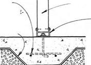
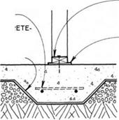
Expansion joints—Expansion joints allow slabs to expand and contract slightly with temperature changes. They also allow slabs to act independently of building elements with which they interface. Expansion joints are appropriate at the edges of slabs that are not heated (not in the living space) or that, for some other reason, are expected to change temperature significantly over their lifetimes. Expansion joints are also used to isolate building elements that penetrate slabs such as structural columns, walls, or plumbing (see 25B).
Control joints—Control joints induce cracking to occur at selected locations. They are troweled or cut into the surface of a slab to about one-quarter of the slab depth and at 20-ft. intervals. Cold joints, which automatically occur between sections of a slab poured separately, can act as control joints.
|
|
||
|
|||
|
|||
 |
|||
|
|||
|
|||
|
|||
|
|||

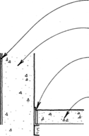


4-IN. (MiN.) REiNFORCED SLAB CONTiNUOUS WITH FOOTING
|
|
NOTE
an uninsulated & exposed perimeter slab IS appropriate ONLY For uNHEATED spaces or in very warm climates.
NOTE
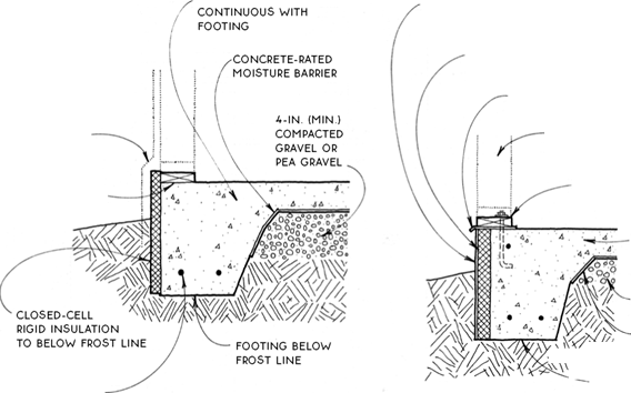
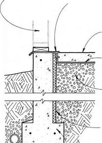
SLABS LOSE HEAT MOST READILY AT THEIR PERIMETERS. WHERE THEY ARE EXPOSED TO THE AIR. SO SLABS MUST BE PROTECTED FROM HEAT LOSS BY A CLOSED-CELL RIGID INSULATION PLACED AT THEIR EDGES. THE AMOUNT OF INSULATION REQUIRED WILL DEPEND ON THE CLIMATE AND ON WHETHER THE SLAB IS HEATED.
THE POSITION OF THE INSULATION WILL DEPEND PRIMARILY ON THE FOUNDATION ТУРЕ. SLABS INTEGRAL WITH TURNED-DOWN FOOTINGS ARE INSULATED AT THE OUTSIDE BUILDING EDGE. SLABS WITH DEEP FOOTINGS ARE OFTEN INSULATED AT THE INSIDE FACE OF THE FOUNDATION. ALTHOUGH THEY MAY ALSO BE INSULATED AT THE OUTSIDE BUILDING EDGE.
|
|
turned-down deep footings
Footings SEE 23A, B & D
SEE 220 & D, 230
|
|
|
||
|
|||
 |
|||
|
|||
|
|||
|
|||
|
|||
|
|||
 |
|||
|
|||
![]()


![]()


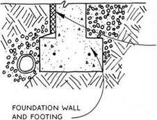
FOuNDATION wALL And FOOTING
closed-cell RiGiD iNSuLATiON TO BELOw Frost LiNE OR 2 Ft. (MiN.)
SEE 22B
Horizontal Interior Insulation
|
|
|
|
|
|
|
|
|
|
|
|
|
|
|
|
|
|

Frost-Protected Shallow Footing
|
|||||
|
|
|
|||
|
|||||
|
|||||
|
|||||
|
|||||
|
|||||
|
|||||
|
|||||
|
|||||
 |
|||||
|
|||||
|
|||||
|
|||||
|
|
|||||
|
|||||
|
|||||
|
|||||
|
|||||
|
|||||
|
|||||
|
|||||
|
|||||
|
|||||
|
|||||
|
|||||
|
|||||
|
|||||
|
|
|||||
|
|
|||||
 |
 |
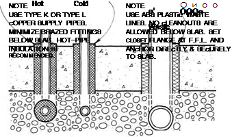 |
Utilities
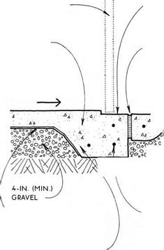
A GARAGE SLAB/FQUNDATIQN WALL ҐВ PLUMBING THROUGH SLAB
 NOTE
NOTE
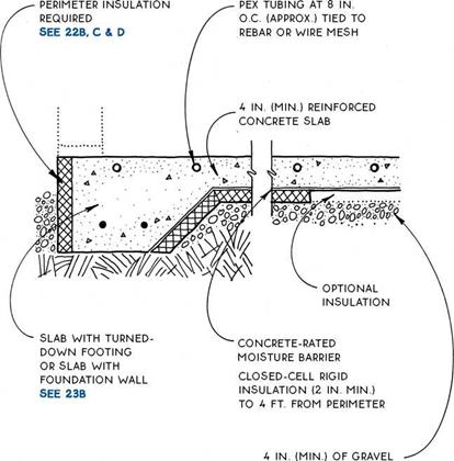
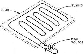
cROSS-LiNKED POLYETHYLENE TUBING (PEX) HAS REPLAcED cOPPER TUBING AS THE cONvEYOR OF HOT WATER FOR RADIANT SLABS. THIS ELASTic TUBING IS SUPPLIED IN LONG ROLLS & cAN cOvER ABOUT 200 SQ. FT. WITHOUT ANY JOINTS BELOW THE SURFAcE. THE ADDITION OF INSULATION BELOW THE SLAB WILL IMPROvE THE PERFORMANcE OF THE SYSTEM.
|
|



Leave a reply