Floor
|
T |
he floor is the part of the building with which we have most contact. We walk on the floor and, on occasion, dance, wrestle, or lie on it. We can easily tell if the floor is not level, if it is bouncy or squeaky, and this tells us something about the overall quality of the building. The floor carries the loads of our weight, all our furniture, and most of our other possessions. It also acts as a diaphragm to transfer lateral loads (e. g., wind, earthquake, and soil) to the walls, which resist these loads. Floors insulate us from beneath and often hold ductwork, plumbing, and other utilities. So a floor must be carefully designed as a system that integrates with the other systems of a wood-frame building—the foundation, walls, stairs, insulation, and utilities. Once designed, the floor must be carefully built because so many subsequent parts of the construction process depend on a level and solid floor construction.
|
|
elements of a floor system
There are several floor-construction systems, and all of them are composed of variations of the same basic elements: support, joists, and a subfloor.
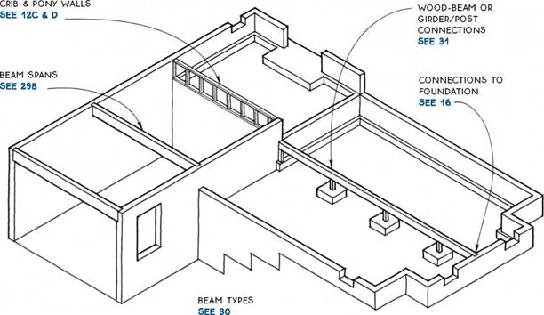
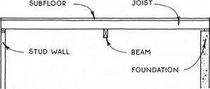
Support—Wood floor systems usually span between parallel supports. These supports may be a foundation wall, a stud-bearing wall, or a beam. The first two are covered in Chapters 1 and 3, and beams are a subject of this chapter (see 29-31).
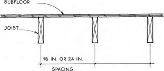
Joists—The primary structural members of a floor system are the joists, which span between the supports. The most common materials for joists are solid-sawn lumber (see 35-42) and engineered wood I-joists (see 43-44). Joists are usually placed on 12-in., 16-in., or 24-in. centers, depending on the required span and the sizes of the joists (see 32).
Subfloor—The planar structural surface attached to the top of the joists is called the subfloor (see 48-51). The subfloor provides the level surface to which the finish floor is applied, and it also acts as a diaphragm to transfer lateral loads to the walls. Subfloors are usually made of plywood or oriented strand board (OSB) but may also be made of other materials. Some subfloors also provide mass for passive-solar heating.
floors and walls
It is essential to coordinate the details of a floor-framing system with those of the wall framing. There are two wall-framing systems from which to choose:
Balloon framing—Balloon framing is a construction system in which the studs are continuous through the floor levels. It is a mostly archaic system, but there are some situations where balloon framing is appropriate. These situations are discussed in the introduction to Chapter 3 (see 65-66). Balloon-framing details that pertain to floors are included in this chapter.
Platform framing—Platform framing is the dominant wood-floor construction system in this country. The platform frame floor is so named because the stud-wall structure stops at each level, where the floor structure provides a platform for the construction of the walls of the next level. This chapter concentrates on platform framing, which has two basic variations: joists with structural panels (OSB or plywood), and girders with decking.
types of floor framing
Throughout the history of the balloon frame and the more recent platform frame, floors have typically been made with joists (2×6, 2×8, 2×10, and 2×12) that are spaced closely (usually 16 or 24 inches on center) to support a subfloor that spans between them.
|
|
For 125 years, the joists were all solid-sawn lumber, and the subfloor started as boards, laid diagonally and later became plywood. In the past 35 years or so, solid – sawn lumber has been slowly replaced with engineered wood products—wood I-joists and other structural composite lumber (SCL). Engineered wood products are straighter, more dimensionally stable, and generally stronger than their solid-sawn counterparts. In addition, they can be made larger and longer than sawn lumber, so they can span farther.
Currently, engineered wood products have overtaken solid-sawn lumber in terms of market share for floor construction, but both materials are still widely used. Subfloors are now typically made with Oriented Strand Board (OSB) instead of the more expensive plywood.
Most of the details in this chapter are illustrated with examples showing solid-sawn lumber—primarily because the drawings are more clear using these simple forms. However, the solid-sawn details may be interpreted to be built of engineered products because the basic principles apply to all types of framing material whether solid-sawn, I-joist, or other composite materials. Because I-joists require special treatment in certain conditions, there is a section of the chapter devoted entirely to I-joists (see 43-44).
In areas where timber is plentiful, 4x girders with 2-in. tongue-and-groove subfloor decking that spans 4 ft. are often used as a floor system (see 46-47).
Lower grades of decking on girders make a very economical floor over crawl spaces, and appearance grades of decking are often used for exposed ceilings. The decking itself does not technically act as a diaphragm to resist lateral loads, so it may require additional diagonal structure, especially at upper levels.
Also included in this chapter are porch and deck floors, floor insulation, and vapor barriers.
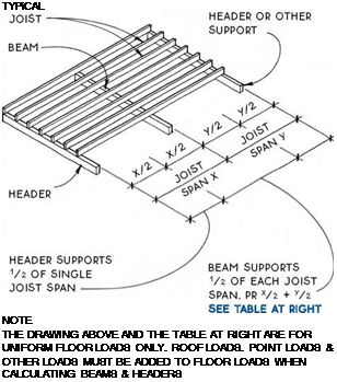
Joist span (У2 + У2)
|
Beam type |
8ft. |
10ft. |
12ft. |
14ft. |
|
Beam span (ft.) |
||||
|
(2) 2×8 built-up beam |
6.8 |
6.1 |
5.3 |
4.7 |
|
4×8 timber |
7.7 |
6.9 |
6.0 |
5.3 |
|
31/8 in. x 7У2 in. glue-laminated beam |
9.7 |
9.0 |
8.3 |
7.7 |
|
3V2 in. x 7У2 in. PSL beam |
9.7 |
9.0 |
8.5 |
8.0 |
|
(2) 13/4 in. x 71/2 in. LVL (unusual depth) |
10.0 |
9.3 |
8.8 |
8.3 |
|
4×8 steel beam |
17.4 |
16.2 |
15.2 |
14.1 |
|
(W8 x 13 A36) |
This table assumes a 40-psf live load and a 15-psf dead load. The table is intended only for estimating beam sizes and comparing beam types. For calculation tables, consult the national or regional organizations listed on pp. 228-229.
A) FLOOR beams
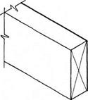
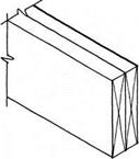
TIMBER BEAMS ARE AVAiLABLE IN A VARIETY OF SPECIES & GRADES; DOUGLAS-FIR IS THE STRONGEST. ACTUAL WIDTHS ARE 31/2 IN. AND 51/2 IN.; ACTUAL HEIGHTS ARE 51/2 IN., 71/2 IN., ETC., TO 131/2 IN.
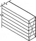
SOLID SAWN LUMBER IS NAILED OR SCREWED TOGETHER TO FORM A SINGLE BEAM. WIDTHS ARE MULTIPLES OF 11/2 IN. HEIGHT FOLLOWS DIMENSION LUMBER.
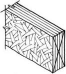
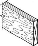
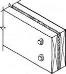
Laminated-Strand Lumber (LSL) Beam
FACTORY-MADE COMPOSITE BEAM USED FOR HEADERS, RIM JOIST, AND LIGHT-DUTY BEAMS. ACTUAL WIDTHS ARE 13/4 IN. AND 31/2 IN; ACTUAL HEIGHTS RANGE FROM 91/4 IN. TO 16 IN.
Parallel-Strand Lumber (PSL) Beam
FACTORY-GLUED LONG STRANDS OF VENEER MAKE VERY STRONG BEAMS. ACTUAL WIDTHS RANGE FROM 23/4 IN.
TO 7 IN; HEIGHTS RANGE FROM 91/4 IN. TO 18 IN. 51/2 IN., 71/2 IN., ETC., TO 131/2 IN.
A STEEL PLATE SANDWICHED BETWEEN TWO PIECES OF LUMBER ADDS STRENGTH WITHOUT SUBSTANTIALLY INCREASING THE BEAM SIZE. THE LUMBER PREVENTS BUCKLING OF THE STEEL & PROVIDES A NAILING SURFACE. WIDTHS ARE 3 IN. TO 31/2 IN. HEIGHTS FOLLOW DIMENSION LUMBER.
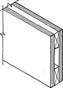
2X4 LUMBER IS SANDWICHED BETWEEN TWO PLYWOOD SKINS. PLYWOOD IS BOTH NAILED & GLUED TO 2X4S & AT ALL EDGES. PLYWOOD AND LUMBER JOINTS MUST BE OFFSET.
Laminated-Veneer Lumber (LVL) Beam
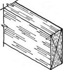
FACTORY-LAMINATED VENEERS MAKE STRONG BEAMS. USED INDIVIDUALLY OR GANGED TOGETHER. ACTUAL WIDTH IS – Із/* IN. (TWO PIECES MATCH THICKNESS OF 2X4 WALL) HEIGHTS RANGE FROM 51/2 IN. TO 24 IN.
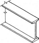
THE STRONGEST OF THE BEAMS FOR A GIVEN SIZE, STEEL BEAMS ARE COMMONLY AVAILABLE IN VARIOUS SIZES FROM 4 IN. WIDE & 4 IN. HIGH TO 12 IN. WIDE &
36 IN. HIGH. THEY MAY BE PREDRILLED FOR BOLTING WOOD PLATE TO TOP FLANGE OR TO WEB.
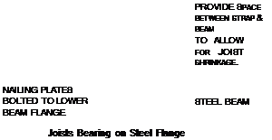
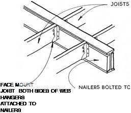
 FOR CONNECTIONS TO STEEL BEAMS SEE 37.
NOTE
BEAMS & JOISTS MUST BE DESIGNED AS A SYSTEM. CONNECTIONS BETWEEN JOISTS & BEAMS ARE SIMILAR FOR ALL WOOD-BEAM TYPES.
SEE 36
|
|
NOTE
 |
 |
 |
 |


 |
 |
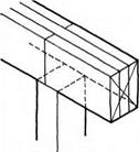
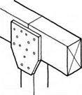
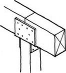
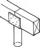
WOOD BEAMS MAY BE SPLICED OVER VERTICAL SUPPORTS & OFTEN MAY BE ATTACHED TO THE SUPPORT BY MEANS OF TOENAILING. SOME SITUATIONS & CODES. HOWEVER. REQUIRE A POSITIVE CONNECTION OF BEAM TO POST SUCH AS A PLYWOOD GUSSET OR METAL CONNECTOR. SPLICE BEAMS ONLY OVER VERTICAL SUPPORTS UNLESS ENGINEERED. SPLICE WILL DEPEND ON ТУРЕ OF BEAM & ТУРЕ OF SUPPORT.
(д) WOOD BEAM OR GIRDER/POST CONNECTIONS

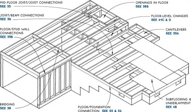
Both dimension-lumber and wood I-joists are common materials for floor structure. Both systems are flexible, and the materials are universally available. Species of lumber vary considerably from region to region, but sizes are uniform. The most common sizes for floors are 2×8, 2×10, and 2×12. Selection of floor – joist size depends on span; on spacing required for subflooring and ceiling finishes (usually 12 in., 16 in., or 24 in.); and on depth required for insulation (usually over a crawl space) and/or utilities (over basements and in upper floors).
The table at right compares spans at common on – center spacings for three typical species and grades of framing lumber at four different sizes of joist (2×6, 2×8, 2×10, and 2×12) and an I-joist at the two largest sizes. For information on wood I-joists, see 43 and 44; for information on wood trusses, see 45A.
This table assumes a 40-psf live load, a 10-psf dead load and a deflection of L/360. The table is for comparison and estimating purposes only.
|
ALLOWABLE FLOOR JOiST SPANS iN FEET
|
NOTE
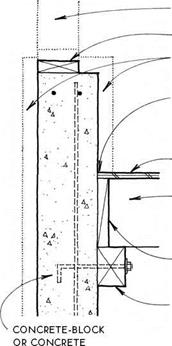
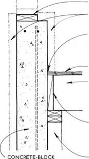
iN EARTHQUAKE OR HURRiCANE zONES, SEcuRE Floor JOiSTS TO MuDSiLL with framing anchors. FOR JOiST span table SEE 32.
FRAMED WALL

![]()


![]()

![]()
![]()



![]()
![]()
 |
 |
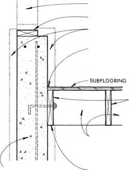
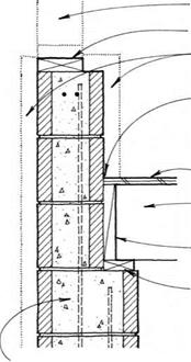
p. T. MUDSiLL SEE 12A
EXTERiOR OR INTERIOR INSULATION SEE 150
30-LB. FELT MOiSTURE BARRiER BETWEEN FOUNDATiON WALL & UNTREATED WOOD
SUBFLOORING
JOIST W/ FULL BEARING ON 2X4 SILL
blocking BETWEEN JOiSTS
p. T. 2X4 SILL W/ 1/2-IN. anchor BOLTS AT 6 FT O. c.
NOTE
FOR DETAIL W/ JOiSTS pARALLEL TO WALL SEE 33B.
 Perpendicular to Wall/Stepped Wall Support

 |
 |
 |
|
 |
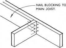
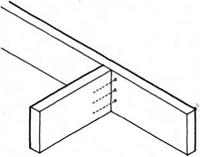
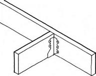
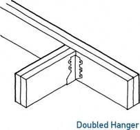
THiS iS the strongest of the standard methods. each approved HANGER iS RATED iN pounds.
notes
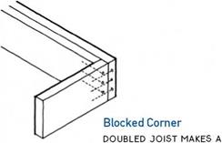 for metal hangers, use common (not box)
NAiLS. HANGER MANuFACTuRERS SpEciFY NAiL
SizE for each hanger type.
use coNSTRucTioN ADHESivE AT METAL JoiST HANGERS To REDucE FLooR SQuEAKING.
for floor openings SEE 38B.
STRONG OUTSIDE CORNER FOR CANTILEVERS SEE 39A AND DECKS SEE 52
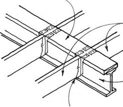
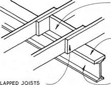
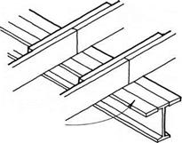
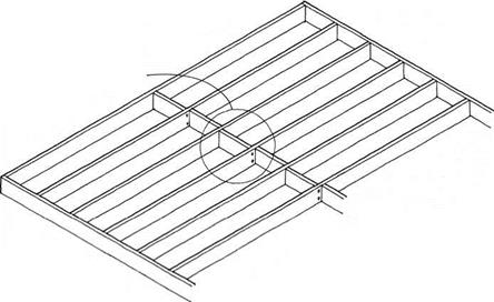
/дЛ JOIST/JOIST CONNECTIONS
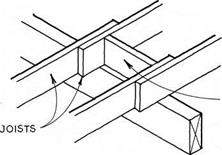
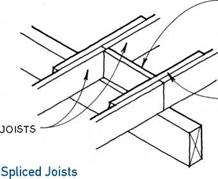
BuTT JOiSTS TO MAINTAIN SAME SpAciNG FOR NAILING THE SuBFLOOR ON EAcH SIDE OF THE BEAM.
NOTE
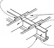
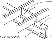
LAppED JOiSTS & SpLicED JOiSTS ARE cOMMONLY uSED OvER A cRAwL Space OR OTHER LOcATION
where head clearance below the beam is NOT required.
![]()
![]()


 |
 |
 |
A 2X2 OR 2X4 LEDGER NAILED TO THE BEAM SuppORTS THE JOiSTS. TOENAIL THE JOiSTS TO THE BEAM OR BLOcK BETwEEN JOiSTS. NOTcH JOiSTS TO 1/4 OF depth IF required TO FIT OVER THE LEDGER.
NOTE
JOIST HANGERS & JOiSTS ON LEDGER ARE uSED wHERE MAXIMuM HEAD cLEARANcE IS REQuiRED BELOw THE FLOOR. THEY wORK BEST IF THE JOiSTS & BEAM ARE OF SIMILAR SpEciES & MOISTuRE cONTENT SO THAT ONE DOES NOT SHRINK MORE THAN THE OTHER.

|
|
|
|
|
|
 |
|
|
|
|
|
|
|
|
|
|
|
|
|
|
|
|
|
|
 |
|
|
|
 |
|
|
|
|
|
|
|
|
|
|
|
|
|
|
|
|
|

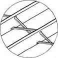 |
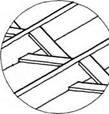
note
for deep JOiSTS wiTH long spans (Over 10 ft.), local codes may REQuiRE Bridging TO pREvENT ROTATiON & TO Distribute THE LOADING.
METAL PiECES SHOULD
not touch each other.
5AX3 OR 5AX4 OR 2X2 OR 1X4 BOARDS ARE NAILED IN A cROSS PATTERN BETWEEN JOiSTS. PiEcES SHOULD NOT TOUcH EAcH OTHER.
|
|
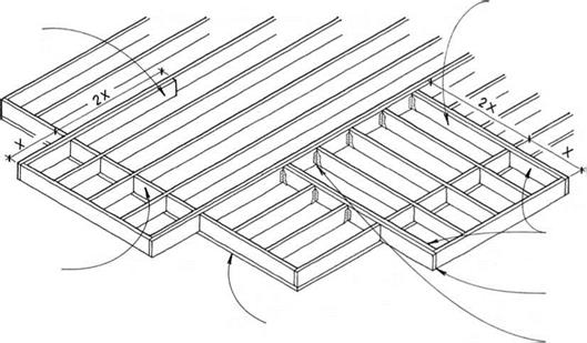
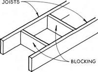
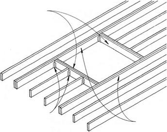
OPENINGS THAT FIT BETWEEN TWO JOiSTS FOR LAUNDRY cHUTES OR HEATING DUcTS ARE SIMPLY MADE BY NAILING BLOcKiNG BETWEEN THE JOiSTS.
IN OPENINGS THAT ARE WIDER THAN THE JOIST SPAciNG, SUcH AS FOR THE STAIRWAYS & cHIMNEYS, THE FLOOR STRUCTURE AROUND THE OPENING MUST BE STRENGTHENED. FOR OPENINGS UP TO THREE JOIST SPAcES WIDE, DOUBLE THE JOiSTS AT THE SIDES & ENDS OF THE OPENING MAY SUFFicE. WIDER OPENINGS SHOULD BE ENGINEERED.
OPENINGS IN JOIST-FLOOR SYSTEM
|
|
||
|
|||
|
|||
|
|||
|
|||
|
![]()

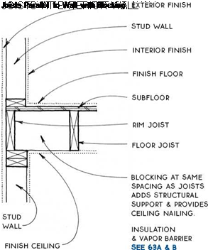
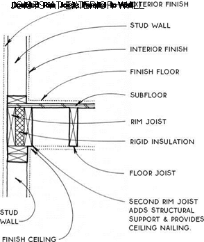
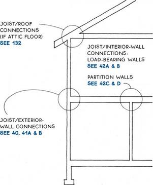 Joist floor-system connections to exterior walls are straightforward. The wall framing may be one of two types.
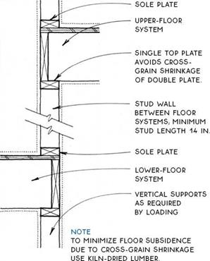
Platform framing – Platform framing, the most common system in use today, takes advantage of standard materials and framing methods. The ground floor and all upper floors can be constructed using the same system.
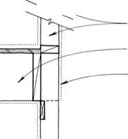
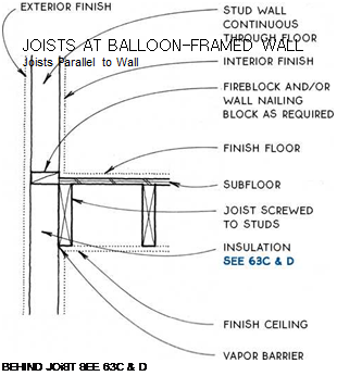
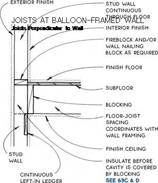
Balloon framing – Balloon framing is rarely used because it is harder to erect and requires veiy long studs. It may be the system of choice, however, if the floor structure must work with the walls to resist lateral roof loads or if extra care is required to make the insulation and vapor barrier continuous from floor to floor, (see 41A, B)
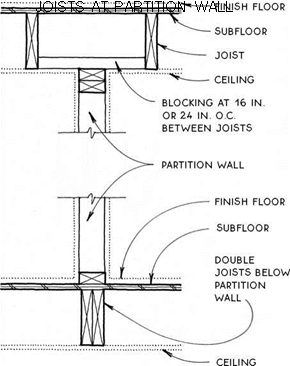
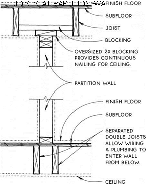
Joist floor-system connections to interior walls depend on whether the walls are load-bearing walls or partition walls. The other factor to consider is whether edge nailing is required for the ceiling.
EXTERiOR Finish
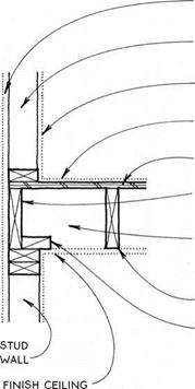
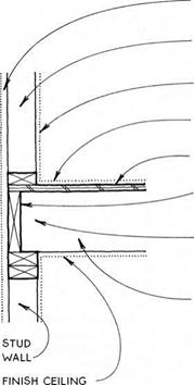 stud wall
INTERIOR FiNiSH FiNiSH FLOOR SuBFLOOR Rim JOiST
insulation & vapor barrier SEE 63A & B
FLOOR JOiST
2X4 Blocking FOR NAILING
![]()
 |
 |
ceiling
![]()
 |
 |
![]()

![]()
 |
 |
NOTE
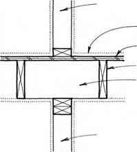
STuD LAYOuT MuST BE OFFSET 11/2 IN. FROM JOIST LAYOuT.
continuous studs avoid the cross-grain shrinking OF
PLATES IN DETAIL SEE 41C.
BEARING STuD WALL; STuDS ALIGNED WITH joiSTS &
![]()




studs below
FINISH FLooR
subfloor
joist
block if joist is spliced over
BEARING WALL SEE 36A
BEARING STuD WALL (oR BEAM) below; studs ALIGNED WITH JoiSTS (BEARING WALL IS
not required if joists ARE
 |
 |
ENGINEERED To Support Top BEARING WALL).
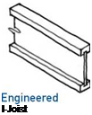
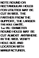
Wood I-joists are designed to work efficiently, with most of the wood located at the top and bottom of the joist where the bending stresses are greatest. Called flanges, the top and bottom are generally made of laminated or solid wood; the slender central part of the joist, the web, is made of plywood or OSB. I-joists are straighter and more precise than dimension lumber and therefore make a flatter, quieter floor. Their spanning capacity is only slightly greater than that of dimension lumber, but because they can be manufactured much deeper and longer than lumber joists (up to 30 in. deep and 60 ft. long), they are the floor-framing system of choice when long spans are required.

![]()

![]()
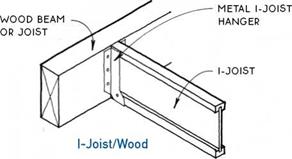
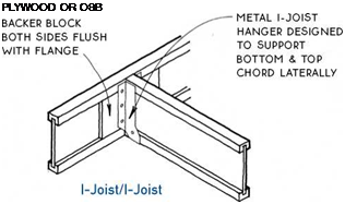

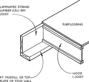
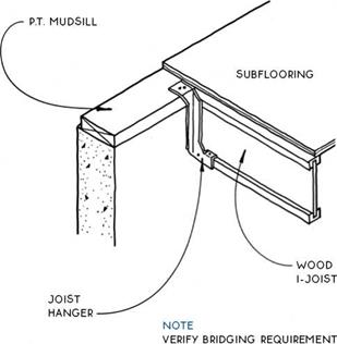
![]() Wood I-joists are designed to be part of a system composed of engineered beams, joists, and sheathing. Laminated strand lumber (LSL) rim joists and laminated veneer lumber (LVL) beams are sized to integrate with the joists. In cases of extreme loading, composite beams may be substituted for I-joists. The system is completed with span-rated tongue-and-groove sheathing nailed to the joists and reinforced with construction adhesive.
Wood I-joists are designed to be part of a system composed of engineered beams, joists, and sheathing. Laminated strand lumber (LSL) rim joists and laminated veneer lumber (LVL) beams are sized to integrate with the joists. In cases of extreme loading, composite beams may be substituted for I-joists. The system is completed with span-rated tongue-and-groove sheathing nailed to the joists and reinforced with construction adhesive.
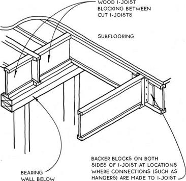
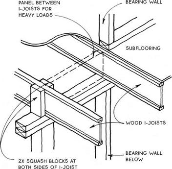
Because the web is thin, I-joists are about 50% lighter than lumber joists. But the thin web also means I-joists do not have as much strength to resist vertical crushing forces. For this reason, the web often must be reinforced with plywood or OSB web stiffeners. Nailed to the web, these stiffeners occur at connectors for deep joists, and in other conditions as required by manufacturers’ specifications and local codes. When vertical loads are extreme, I-joists can be reinforced by attaching sections of 2x framing lumber called squash blocks to their sides or by fastening LSL blocking panels between them (see 44C).
When other framing members need to be attached to the side of an I-joist, backer blocks are added to the webs of the I-joists. Like web stiffeners, backer blocks are made of plywood or OSB, but their primary purpose is to provide a planar, thick nailing surface rather than to resist vertical loads (see 44D).
Like dimension lumber, wood I-joists are easily cut and joined on site. The production and fastening of backer blocks, web stiffeners, and so forth for I-joist systems can offset the construction time gained by not having to sort for defects.

|
|
|
|
Joists Flush with Mudsill
|







Leave a reply