About the drawings
The sizes of building elements indicated in the drawings in this section are for the purposes of illustrating principles and reminding the designer and the builder to consider their use carefully. These drawings should therefore be used only for reference.
![]()
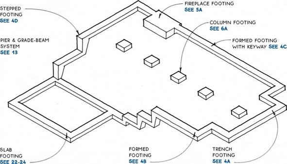 |
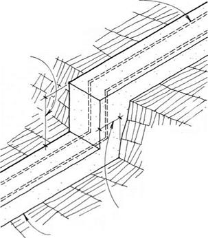
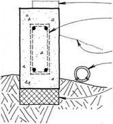
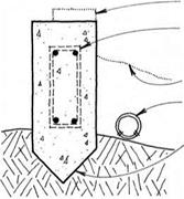
Footings are the part of a foundation that transfers the building’s loads—its weight in materials, contents, occupants, and snow, and possibly wind and earthquake loads—directly to the ground. Consequently, the size and type of footing should be matched carefully to the ground upon which it bears.
Soil type—Concrete footings should be placed on firm, undisturbed soil that is free from organic material. Soil types are tested and rated as to their ability to support loads (bearing capacity).
Compaction of soil may be required before footings are placed. Consult a soil engineer if the stability of the soil at a building site is unknown.
|
r SOIL TYPE |
BEARING CAPACITY (PSF) 1 |
|
Soft clay or silt |
do not build |
|
Medium clay or silt |
1,500-2,200 |
|
Stiff clay or silt |
2,200-2,500 |
|
Loose sand |
1,800-2,000 |
|
Dense sand |
2,000-3,000 |
|
Gravel |
2,500-3,000 |
|
Bedrock |
4,000 and up |
Reinforcing—Most codes require steel reinforcing rods (called rebar) in footings. Rebar is a sound investment even if it is not required, because it gives tensile strength to the footing, thereby minimizing cracking and differential settling. Rebar is also the most common way to connect the footing to the foundation wall. For rebar rules of thumb, see 5B.
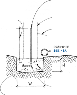
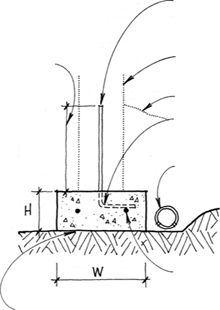
Size—Footing size depends mainly on soil type and the building’s weight. The chart below shows footing sizes for soils with bearing capacities of 2,000 pounds
|
per square foot |
(psf). |
|
|
Г NO. OF STORIES |
H |
W |
|
1 |
6 in. |
12 in. |
|
2 |
7 in. |
15 in. |
|
3 |
8 in. |
18 in. |
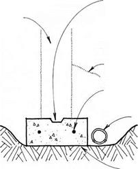
A rule of thumb for estimating the size of standard footings is that a footing should be 8 in. wider than the foundation wall and twice as wide as high.
Frost line—The base of the footing must be below the frost line to prevent the building from heaving as the ground swells during freezing. Frost lines range from 0 ft. to 6 ft. in the continental United States. Check local building departments for frost-line requirements.
|
|
|
|||
|
|||||
|
|||||
|
|||||
|
|||||
|
|||||
|
|||||
|
|||||
|
|
|||||
|
|
|||||
|
|||||
|
|||||
|
|||||
|
|||||
|
|||||
|
|||||
|
|||||
|
|||||
|
|||||
|
|||||
|
|||||
|
|
|

|
|
|
|
|
|
|
|
|
|
|
|
|
|
|
|
|
|
|
|
|
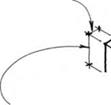
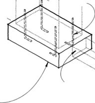
Column footings (also called pier pads) support columns in crawl spaces and under porches and decks. Place all footings on unfrozen, undisturbed soil free of organic material. The bottom of the footing must be located below the frost line unless it is within a crawl space. Columns may need to be anchored to column footings to prevent uplift caused by wind or earthquake forces (see 6B).
Typical sizes are 12 in. to 14 in. for square footings or 16-in. to 18-in. diameter for round footings.
Extreme loads may require oversize footings. The vertical load divided by the soil bearing capacity equals the area of footing, e. g.,
6,000 lb. – 2,000 psf = 3 sq. ft.
To prevent moisture in the footing from damaging the column, use a pressure-treated wood column or place a 30-lb. felt moisture barrier between an untreated wood column and a concrete footing, or use steel connectors where required (see 6B).
|
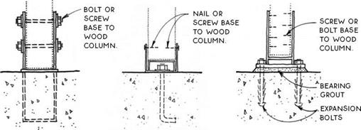

GALVANIZED STEEL STRAP IS OFTEN USED IN CRAWL SPACES OR UNDER PORCHES.
NOTE
USE PT. WOOD COLUMN OR PLACE 30-LB. FELT MOISTURE BARRIER BETWEEN UNTREATED POST & CONCRETE.
MULTIPLE-PIECE GALVANIZED STEEL ASSEMBLY ALLOWS FOR SOME LATERAL ADJUSTMENT BEFORE NUT IS TIGHTENED. BASE ELEVATES WOOD COLUMN ABOVE CONCRETE FOOTING.
EXPANSION BOLTS ARE DRILLED INTO FOOTING OR SLAB AFTER CONCRETE IS FINISHED. ALLOWING FOR PRECISE LOCATION OF COLUMN.
NOTE
EXPANSION BOLTS REQUIRE SPECIAL INSPECTION IN MOST JURISDICTIONS
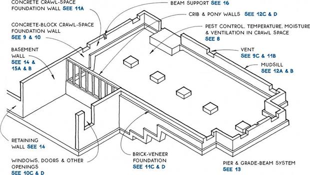
Foundation walls act integrally with the footings to support the building. They also raise the building above the ground. The primary decision to make about foundation walls is what material to make them of. There are several choices:
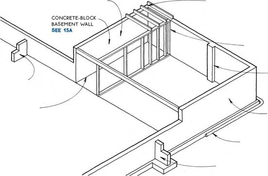
Concrete block—Also known as concrete masonry unit or CMU construction, concrete block is the most common system for foundation walls. Its primary advantage is that it needs no formwork, making it appropriate in any situation, but especially where the foundation is complex. Concrete masonry will be used most efficiently if the foundation is planned in 8-in. increments, based on the dimensions of standard concrete blocks (8 in. by 8 in. by 16 in.).
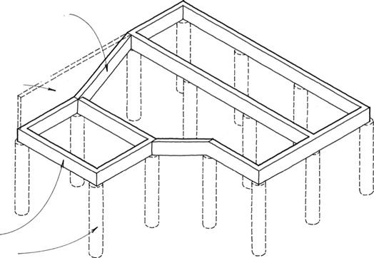
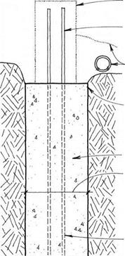
Cast concrete—Concrete can be formed into almost any shape, but formwork is expensive. The most economical use of cast concrete, therefore, is where the formwork is simple or where the formwork can be used several times. Cast-in-place concrete is used for forming pier and grade-beam systems, which are especially appropriate for steep sites or expansive soils (see 13).
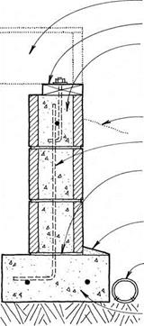
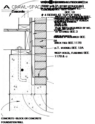
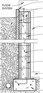
Reinforcing—Some local codes do not require reinforcing of foundation walls. Codes in severe earthquake zones are at the other extreme. As a prudent minimum,
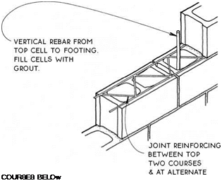
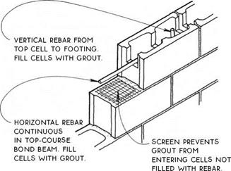
all foundation walls should be tied to the footing with vertical rebar placed at the corners, adjacent to all major openings, and at regular intervals along the wall. There should be at least one continuous horizontal bar at the top of the wall. Joint reinforcing may be an adequate substitute (see 10B).
Width—The width of the foundation wall depends on the number of stories it supports and on the depth of the backfill, which exerts a lateral force on the wall. With minimum backfill (2 ft. or less), the width of the wall can be determined from the chart below.
The design of basement walls and foundation walls retaining more than 2 ft. of backfill should be verified by an engineer or an architect.
The minimum height of a foundation wall should allow for the adequate clearance of beams and joists from the crawl-space floor. A code-required 18-in. clearance usually requires 12-in. to 24-in. foundation walls, depending on the type of floor system.
|
r NO. OF STORIES |
FOUNDATION WIDTH |
|
1 |
6 in. |
|
2 |
8 in. |
|
2 |
10 in. |
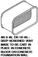
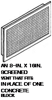
 Moisture— Even with the best drainage, the soil under crawl spaces always carries some ground moisture, which will tend to migrate up to the crawl space in the form of vapor. This vapor can be substantially controlled with a vapor retarder laid directly on the ground, which must first be cleared of all organic debris. Crawl-space vapor retarders should be 6-mil (min.) black polyethylene. The dark plastic retards plant growth by preventing daylight from reaching the soil. Adding a concrete rat slab over the vapor retarder will enhance its effectiveness and durability.
Moisture cannot be allowed to build up in a crawl space where it can create catastrophic damage caused by mildew, fungus, and other organisms dependent on moisture. There are two basic strategies to remove the moisture – ventilation to the outside, and conditioning the air as part of the air volume inside the building.
In both cases, air is moved through the crawl space to replace moisture-laden crawl-space air.
Ventilation—Crawl-space cross ventilation minimizes the buildup of excess moisture under a structure. In some regions, crawl-space ventilation is also required to remove radon gas.
The net area of venting is related to the under-floor area and to the climatic and groundwater conditions. Most codes require that net vent area equals У150 of the under-floor area with a reduction to У1500 if a vapor barrier covers the ground in the crawl space. Screened vents should be rated for net venting area.
Vents should supply cross ventilation to all areas of the crawl space. Locating vents near corners and on opposite sides of the crawl space is most effective.
Access doors can provide a large area of ventilation. Wells allow vents to be placed below finished grade.
As shown in the drawing above right, screened vents are available for installing in masonry, cast concrete, and wood. They are available in metal or plastic, and some have operable doors for closing off the crawl space during winter to conserve heat. Operable vents should be closed only during extreme weather conditions. Closing the vents for an entire season will increase moisture in the crawl space and can significantly increase the concentration of radon gas.
Unvented crawl space – In climates with humid summer weather, ventilation actually brings moisture into a crawl space, where hot, humid air contacts cooler surfaces in the crawl space and condenses there. The best solution in this case is to insulate the crawl space, close it up tight, and heat and cool it as if it were another room. It doesn’t add much to the heating or cooling load, being a small volume with little exterior wall area. This strategy is also appropriate in other climates.
Unvented crawl spaces must be insulated at the foundation wall. The insulation can be installed using the same details as for a basement wall (see 15C). Care must be taken to seal the space well against air infiltration. This includes sealing the joint between foundation wall and mudsill (see 12A) and sealing the joints of the floor assembly that bears on the mudsill (see 33-34).
Pests—Rodents and other large burrowing pests can be kept out of crawl spaces by means of a “rat slab,” which is a 1-in. to 2-in.-thick layer of concrete poured over the ground in a crawl space. A concrete-rated moisture barrier should be placed below this slab (see 20). Termites and other insect pests are most effectively controlled by chemical treatment of the soil before construction begins.
Radon—Radon is an odorless radioactive gas that emerges from the ground and is present at very low concentrations in the air we breathe. This gas can build up to dangerous levels when trapped in a crawl space (or basement). Although present everywhere, radon concentration levels in the earth are higher in some regions, and all of North America has been mapped and evaluated for radon danger. The best protection against radon buildup is to ventilate the crawl space well and/or effectively seal the ground below the building. Radon test kits are readily available.
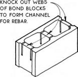

![]()
![]()
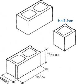

STANDARD WiDTHS ARE 35/8 iN.,
55/8 iN., 75/8 iN., 95/8 iN., AND 115/8 iN. ALL DiMENSiONS ARE ACTUAL.
JAMB BLOCKS ARE AVAiLABLE iN HALF (SHOWN) AND STRETCHER SiZES. iN ONE SiDE A SLOT LOCKS BASEMENT WiNDOWS iN PLACE.
NOTE
ALMOST ANY SiZE OR SHAPE OF MASONRY WALL CAN BE BUiLT WiTH BASiC BLOCK TYPES. CONSULT NCMA FOR CONSTRUCTiON TECHNiQUES AND FOR SPECiAL BLOCKS WiTH SPECiAL EDGE CONDiTiONS, TEXTURES, COLORS, AND SiZES.
|
|
|||
 |
|||
|
|||
|
|||
|
|||
|
|||
|
|||
|
|
|
NOTE

![]()
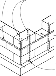
HORiZONTAL REBAR SHOULD BE CONTiNUOUS iN A BOND BEAM AT THE TOP COURSE, OR AT THE SECOND COURSE iF FOUNDATiON VENTS ARE LOCATED iN THE TOP COURSE. HORiZONTAL REBAR MAY ALSO BE LOCATED iN Intermediate BOND Beams If THE HEiGHT, wiDTH & Function OF THE wALL REQUIRE IT.
|
|
BOND-BEAM TOp COURSE wiTH reinforcing SEE 10A
BOND OR LINTEL BLOCKS wiTH GROUT AND REBAR OR REINFORCED CAST- CONCRETE LINTEL vertical REBAR AT BOTH SIDES of opening AND extended INTO FOOTING
CORNER AND HALF
blocks at side jambs

 |
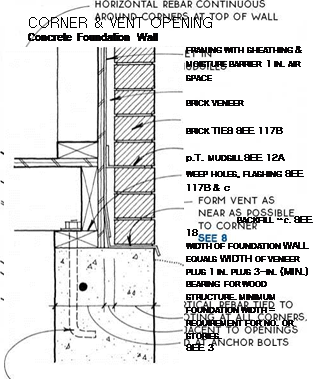 |
Brick below Mudsill
brick-veneer foundation
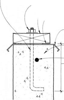
1/2-iN. STEEL ANCHOR BOLT AT 4 FT. OR 6 FT. O. C.
(MAX.) & 12 iN. (MAX.) FROM END OF EACH PiECE OF MUDSiLL. verify wITH LOcAL CODES.
1/2-iN. STEEL NUT WITH STEEL WASHER
2X4 OR 2X6 P. T. WOOD MUDSiLL
SILL GASKET OF CAULK OR FIBERGLASS AT BASEMENTS OR OTHER LIVING SPACE
CONTINUOUS
termite shield in termite regions
CONCRETE OR CONCRETE-BLOCK FOUNDATION WALL REBAR
7-IN. MiN. DEPTH OF ANCHOR BOLT INTO FOUNDATION WALL
NOTE
SOME CODES REQUIRE LONGER BOLTS FOR MASONRY WALLS.
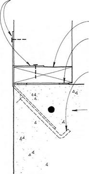
BEND DOUBLE-STRAP ANCHOR AROUND MUDSiLL & NAIL AT SIDE & TOP, OR NAIL ONE STRAP TO MUDSiLL & OTHER TO FACE OF STUD.
2X4 OR 2X6 P. T. WOOD MUDSiLL
SILL GASKET OF CAULK OR FIBERGLASS AT HEATED SPACE
PLACE MUDSiLL ANCHORS INTO FRESH CONCRETE OR NAIL TO FORM BEFORE PLACING CONCRETE.
SLAB WITH TURNED – DOWN FOOTING SEE 22
NOTE
VERIFY ACCEPTABILITY OF MUDSiLL
ANCHOR WITH LOCAL BUILDING CODE.
THE MUDSiLL ANCHOR ALLOWS THE
ABILITY TO FINISH SLAB TO THE EDGE
BUT IT IS DIFFICULT TO USE WITH
TERMITE SHIELD.
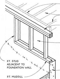
A CRIB WALL IS AN ALTERNATIVE TO COLUMNS & A BEAM SUPPORT FOR JOISTS IN A CRAWL SPACE. IT ALLOWS MORE CLEARANCE FOR DUCTS AND EQUIPMENT & AVOIDS THE POTENTIAL PROBLEM OF CROSS-GRAIN SHRINKAGE IN BEAMS.
A PONY WALL IS USEFUL IN A STEPPED FOUNDATION WALL OR IN A SLOPING PIER & GRADE-BEAM FOUNDATION. THE PONY WALL PROVIDES A LEVEL SURFACE FOR CONSTRUCTION OF THE FIRST FLOOR.

![]()
![]()


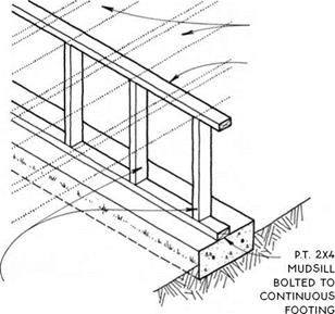
 DOUBLE TOP PLATE CONTINUOUS WITH MUDSiLL
PONY WALL RECEIVES THE SAME EXTERIOR FINISH AS THE FRAMED WALL ABOVE.
|
||
|
||
|
||
|
||
|
||
|
||
|
|
||
|
||
|
||
|
||
|
||
|
||
|
||
|
|
||

|
||
|
||
|
||
|
||
|
||
|
||
|
||
|
||
|
||
|
||
 |
|
|
 |
||
|
||
|
|
![]()

![]()


![]()
![]()
iNSULATiON SEE 15C
BACKFILL AND DRAiNAGE SEE 18B
WATERPROOFING SEE 18C
ALTERNATIVE LOCATION FOR INSULATION
VERTICAL REBAR PLACED AT TENSION SIDE OF WALL RESISTS BENDING FORCES.
BOND BEAMS
as required BY engineering
vertical rebar
ANCHORS wALL TO FOOTING.
SLAB SEE 21C OR D
full mortar joint on roughened
FOOTING
FOOTING SEE 4
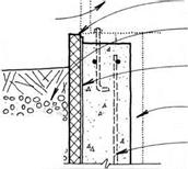
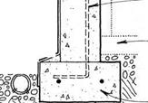
insulation SEE 15C
backfill AND DRAINAGE SEE 18B
waterproofing SEE 18C
alternative location FOR insulation
vertical rebar placed at tension SIDE OF wall RESISTS BENDING FORCES.
horizontal rebar as required by
ENGINEERING
vertical REBAR ANCHORS wALL TO FOOTING.
SLAB
SEE 21C OR D
FOOTING SEE 4

![]()

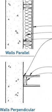
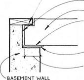
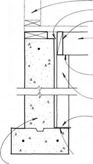
 Heated basements must be insulated at their perimeter walls. The amount of insulation required depends on the climate. There are two ways to insulate basement walls—from the exterior or from the interior.
 Exterior—Exterior insulation should be a closed-cell rigid insulation (extruded polystyrene or polyisocyanurate) that will not absorb moisture. This insulation, available in 2-ft. or 4-ft. by 8-ft. sheets, is attached directly to the basement wall with adhesive or mechanical fasteners. It may be applied either under or over the waterproofing, depending on the type.
Interior—Interior insulation may be either rigid or batt type. Petroleum-based rigid types must be covered for fire protection when used in an interior location. Other rigid insulation, such as rigid mineral fiber, need not be fire – protected. Building a stud wall with batt insulation has the advantage of providing a nailing surface for interior finishes.
|
|
|
|
|||
|
|||
|
|||
|
|||
|
|||
|
|||
|
|||
|
|||
|
|||
|
|||
|
|||
|
|||
|
|||
|
|||
|
|||
|
|||
|
|||
|
|
|
||
|
|
|||

NOTE
![]()
 |
 |
![]()
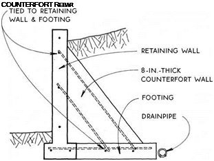
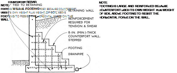
COUNTERFORT MUST BE pROFESSIONALLY ENGiNEERED. REiNFORCEMENT iS REQUiRED FOR TENSiON AND SHEAR.
NOTE
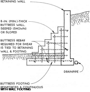 |
BUTTRESS & RETAINING WALL MUST BE PROFESSIONALLY ENGINEERED.



Leave a reply