About the drawings
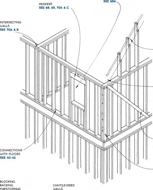
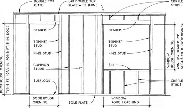
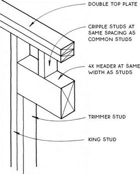
Construction terms vary regionally, and the names for the components that frame wall openings (see 68A) are the least cast in stone. Studs called “trimmer studs” in one locality are called “jack studs” in another; and the bottom plate may go by either “bottom plate” or “sole plate.” Consult local builders and architects for common usage.
For clarity, insulation is not generally shown in the exterior walls except in the insulation section (120-125).
|
|||
|
|||
|
|||
|
|||
|
|||
|
|
resource-efficient advanced framing
SEE 74 NOTE
IN THIS cHAPTER ALL 2×4 wALLS ARE SHOwN with studs AT 16 IN. O. c.; ALL 2×6 wALLS ARE shown with studs at 24 in. o. c..- unlabeled walls МАУ be EITHER 2X4 OR 2X6.
|
|
|


![]()
![]()
 DOUBLE (OR SINGLE) 2X10 HEADER WITH 2X4 SCABBED To Bottom
(eliminates the need for cripple studs in
![]()


![]()


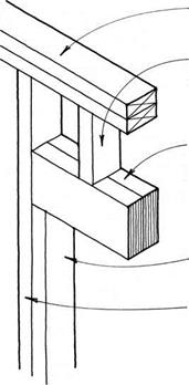 AN 8-FT. WALL)
![]()
|
|
|
![]()

![]()



![]()

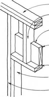
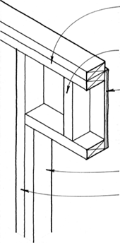 CRIPPLE STUDS AT SAME SPACING AS common STUDS
1/2-in. cdx plywood

(MIN.) NAILED To oNE SIDE oF FRAMING WITH 8D CoMMoN NAILS AT 3 IN. o. C. STAGGERED 1/2 IN. To AVoiD SPLITTING FRAMING
|
|
||
|
|
|
|
|
|
|
|
|
|
 |
|
|
|
|
|
|
|
|
|
|
|
|
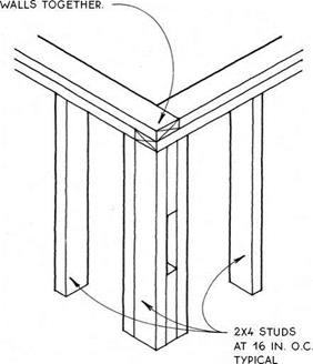
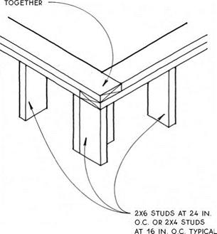
![]()

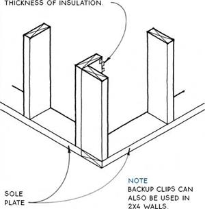
corner studs built up with 2X4 blocking BETWEEN provides nailing at
![]()

![]()

![]()
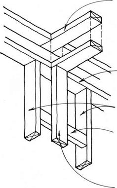 TOP PLATE OF INTERSECTING WALL OVERLAPS CONTINUOUS TOP PLATE OF PRIMARY WALL.
![]()
|
|
|
![]()
![]()
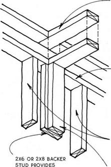
NAILING AND ALLOWS SPACE FOR INSULATION
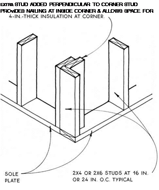
TOP PLATE OF INTERSECTING WALL OvERLAPS CONTINUOUS TOP PLATE OF PRIMARY WALL
END STUD OF INTERSECTION WALL
|
|
||
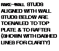
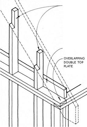
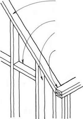
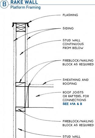
A wall that extends to a sloped roof or ceiling is called a rake wall and may be built one of two ways:
Platform framing—Platform framing is commonly the method of choice when a horizontal structural element such as a floor or ceiling ties the structure together at the level of the top plate or when the top plate itself is short enough to provide the necessary lateral strength (see 72B).
Balloon framing—Balloon framing allows for ease of construction and economy of material and stabilizes a tall wall because the studs are continuous from sole plate to roof (see 72C). Balloon framing can also be employed to stiffen a wall that projects above the roof such as a parapet or railing (see 72D). Balloon framing is greatly preferred in general from a structural perspective where lateral forces are extreme, such as in high-wind areas.
![]()
 For details of rake walls with truss-framed roofs, see 156.
|
|
|
|
|
|
|
|
|
|
|
|
|
|
|
|


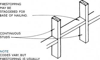 |

 required AT STAIRS alongside THE STRINGERS; BETWEEN floors & BETWEEN THE TOP FLooR & THE attic IN BALLooN-FRAME buildings (THE PLATES IN platform-frame buildings automatically provide fireblocking BETWEEN floors); between wall cavities & concealed horizontal spaces such as soffits & drop cEILINGS; in tall walls every 10 ft. vertically.
firestopping IS usually 2x FRAMING LuMBER but can also be other materials such as LAYERS of plywood or GYPSuM WALLBoARD WHEN approved BY LocAL coDES.
![]() (д) BLOCKING & NOTCHING
(д) BLOCKING & NOTCHING
|
||
|
||
|
||
|
||
|
||
|
||
|
||
|
||
|
||
|
|
||

|
|
|
|
|
|
|
|
|
|
|
|
|
|
|
|
|
|
|
|
|
|
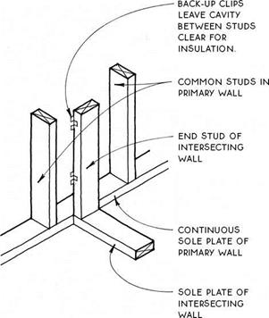
Advanced framing—Advanced framing minimizes the amount of framing that extends from the interior to the exterior of a wall, thus lowering the effect of thermal bridging. By limiting the amount of framing, more volume in the wall can be occupied by insulation, which increases thermal performance of the overall assembly. Advanced framing alone can increase the thermal performance of framed walls by only about
7%, but, given that it uses less material than standard framing and also helps to conserve a precious resource, it should be considered for eveiy framed building. Details of advanced framing are illustrated on 75-76. The goal when designing an energy-efficient header is to allow for the most insulation while providing for nailing at both the exterior and interior of the opening.
|
|
||
|
|||
|
|
![]()

|
|
|
|
|
|
|
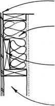
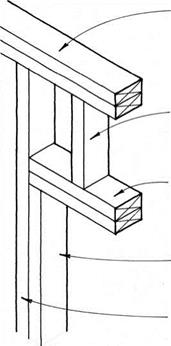
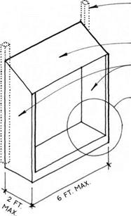
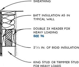
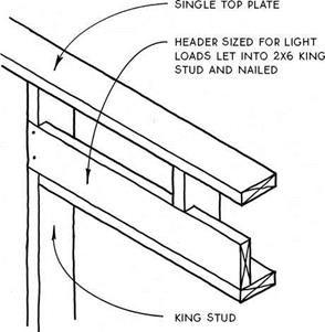
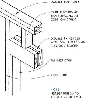
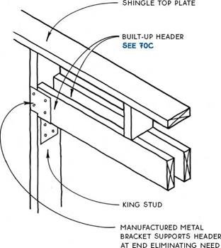
When a structural header is required over an opening in an exterior wall, the header itself occupies space that could otherwise be filled with insulation. Because a deep (tall) header is more effective structurally than a wide one, the header does not usually have to fill the entire width of the wall. In fact, the taller and thinner the header, the more space there will be for insulation. The headers illustrated on this page provide both structure and space for insulation. The box header
(see 69D) also provides space for insulation because it uses sheathing as structure.
The elimination of the trimmer studs that usually support a header at its ends also allows for more insulation in the wall. The header can usually be supported by the king stud as illustrated in the two examples below. (Backing may need to be added to the king studs when wide casings are used.)
|
|
![]()
Most wood buildings are sheathed with plywood, OSB, or other structural panels that provide the necessary lateral stability when fastened directly to the stud frame (see 78-80). Where lateral forces on walls are extreme, such as in areas subject to hurricanes or earthquakes, specially designed shear walls are commonly required to withstand these forces (see 82-87).
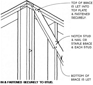
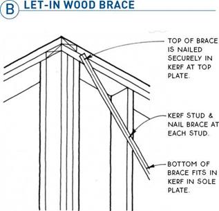
When neither structural panels nor shear walls are required, there are two good methods of bracing the building for lateral stability: the let-in wood brace (see 77B) and the kerfed-in metal brace (see 77C).
The old-fashioned method of bracing with diagonal blocking between studs is not recommended because the nails may withdraw under tension and the many joints tend to open up as the blocking shrinks.
Bracing is often referred to as “corner bracing,” and indeed, the International Residential Code begins its discussion of every allowed wall bracing method with the phrase “located at each end…” While it is true that the corners are the most effective location for a limited amount of wall bracing, it is also possible to successfully brace a building at locations other than the corners. If this were not true, there would be no corner windows. Braces may be located anywhere along a wall, and the bracing effect will be transferred to the rest of the wall through the continuous top and bottom plates. Increased nailing, stronger sheathing, and other methods can also augment bracing. A good structural engineer will be able to design walls of just about any configuration to resist lateral forces.
The methods shown here are located at a corner only for clarity of illustration.
NOTE
LET-IN BRACES SHOULD BE MADE OF STRUCTURALLY SOUND 1X4 OR 1X6 LUMBER. THEY SHOULD BE FROM TOP Plate TO SOLE Plate & 45° TO 60°
FROM THE HORIZONTAL.
|
NOTE METAL BRACING SET IN A SAW KERF & NAILED TO EACH STUD IS ENGINEERED TO EQUAL THE CODE REQUIREMENTS OF A 1X4 WOOD LET-IN BRACE. SURFACE MOUNTED TYPES (WITHOUT KERF) MUST BE INSTALLED IN OPPOSING DIRECTIONS IN AN "X" OR "V" CONFIGURATION. ALL TYPES MUST BE INSTALLED AT 45° TO 60° FROM THE HORIZONTAL. |
|
|
![]()
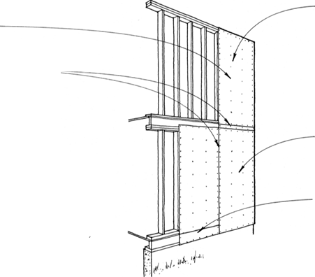
Structural sheathing performs two functions—it provides lateral bracing, and it forms a structural backing for siding materials. OSB is currently the most common structural sheathing, but the use of plywood, gypsum board (which also contributes fire resistance) and other panel products is also widespread. OSB and plywood both have a strength axis along the length of the panel because of the orientation of wood fibers, but this axis
is only important in relation to its bending strength between studs. The panel’s shear strength—its ability to resist lateral forces—is not affected by its orientation.
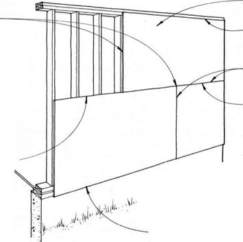
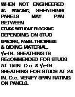
Panels may be installed either vertically or horizontally. Vertically applied sheathing does not usually require blocking because all panel edges are aligned with framing members. Horizontally applied panels, if engineered to provide lateral resistance, must have blocking between studs for nailing. Horizontal OSB and plywood panels provide a stronger backing for siding than do panels with a vertical orientation.
дSTRUCTURAL SHEATHING_________
In earthquake or hurricane zones or where walls are very tall or penetrated by many openings, structural sheathing may require engineering, or shear walls (see 82) may be required.
The capacity of panel products such as OSB and plywood to span between studs is related to thickness. The following chart applies generally:
|
r STUD SPACING |
PANEL THICKNESS 1 |
|
16 in. o. c. |
3/8 in. |
|
24 in. o. c. |
У2 in. |
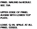
Nails or other approved fasteners should be sized and spaced according to the following schedule. Verify with manufacturer and local codes.
|
PANEL THICKNESS |
NAIL SIZE |
PANEL EDGE NAILING |
FIELD NAILING |
|
У2 in. or less |
6d |
6 in. o. c. |
12 in. o. c. |
|
over У2in. |
8d |
|
|
|
|
|
|
|
|
|
|
|
|
|
|
NOTE
IN REGIONS NOT SUBJECT TO HIGH RISK OF HURRICANE OR EARTHQUAKE, HORIZONTAL PANELS
without blocking & with filler strips at base MAY BE acceptable.
![]() STRUCTURAL SHEATHING/SINGLE-STORY BUILDING
STRUCTURAL SHEATHING/SINGLE-STORY BUILDING

![]()

![]()
![]()

 |
 |
 |
 |
 |
Distance from Mudsill to Top Plate over 8 Ft.
STRUCTURAL SHEATHING/SINGLE-STORY BUILDING
Distance from Mudsill to Top Plate 8 Ft. or Less
In single-wall construction, a single panel of plywood or composite board siding provides both structural and weathering functions. This is an inexpensive, low-quality type of construction most appropriate for garages and sheds, but also used for residential construction. Panels are installed vertically, usually over a moisture barrier.
![]()

![]()

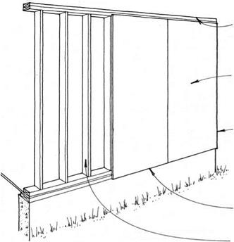
![]() Precut studs (from 88Уз in. to 92% in.) allow 8 – ft. panels to cover the framing on the exterior if the subfloor sits directly on the mudsill (see SOB) or if there is a slab floor. Adding trim to the base allows the use of 8 – ft. panels with taller studs and/or different subfloor connections (see 80C).
Precut studs (from 88Уз in. to 92% in.) allow 8 – ft. panels to cover the framing on the exterior if the subfloor sits directly on the mudsill (see SOB) or if there is a slab floor. Adding trim to the base allows the use of 8 – ft. panels with taller studs and/or different subfloor connections (see 80C).
Taller (9-ft. and 10-ft.) panels are also available.


Leave a reply