RISER DIAGRAMS
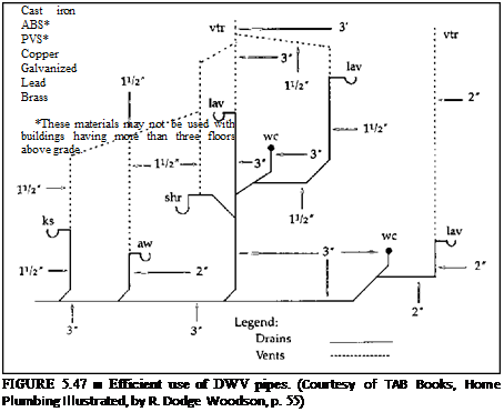
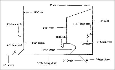
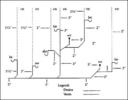
Riser diagrams are often required by code officers prior to any plumbing being installed. Supplying a detailed riser diagram (Fig. 5.44 and Fig. 5.45) is usually a standard part of a permit application. You can also use riser diagrams to help you when sizing a vent system. If
|
FIGURE 5.45 ■ DWV riser diagram, with size and location of pipes. (Courtesy of TAB Books, Home Plumbing Illustrated, by R. Dodge Woodson, p. 50) |
|
FIGURE 5.46 ■ Poorly designed DWV layouts. (Courtesy of TAB Books, Home Plumbing Illustrated, by R. Dodge Woodson, p. 55) |

you draw a riser for the job you are working with, the diagram will make it easier for you to label the fixture-unit loads and the sizes of the vents required. Another good use of a riser diagram is to minimize wasted piping. If you draw your piping path on paper, you can spot situations where an alternative plan might be used to minimize the cost of labor and materials (Fig. 5.46 and Fig. 5.47).


Leave a reply