Design Questions and Plans
We had several conversations about the use of the new space, where the door and windows would go, and the like. We agreed that we wanted plenty of south-facing windows and that they would have to be of some opening style with a screen option. We found some excellent Caradco™ double-hung windows at a good price, but what really sold Jaki on them was that both the upper and lower sashes could be rotated 180 degrees for easy cleaning. After all, there would be no easy access to the windows exterior on the second story.
A nagging question was whether or not we would be able to maintain the same i:i2 roof slope in an upstairs addition and still have sufficient headroom. I checked this with my tape measure and found that there would be plenty of headroom, even at the southern end of the extended five-by-ten roof rafters. We proceeded to the design stage.
 |
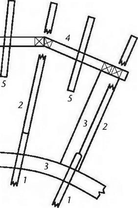 |
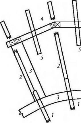
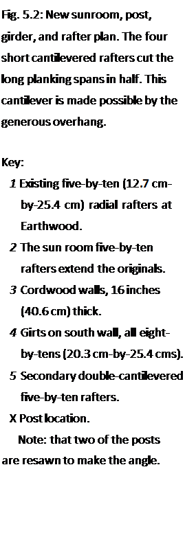
Before tearing the pressure-treated boards off, I used a black crayon to lay out the new room on the outside deck, a great aid in planning. We could visualize and mark all the components in their actual positions. Then, on paper, and using a scale of one-half-inch to the foot, I drew the post-and-beam support structure (Fig. 5.2), and a second plan at the same scale, this one for the replacement four – by-eight system which would serve as the floor support for the new addition. (Fig. 5.3). Note that the primary difference between the upstairs rafter plan and the downstairs ceiling joist plan (apart from timber dimensions) is the way the two different structures support the long planking spans which occur as the extended radial rafters get further apart.
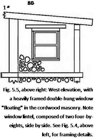
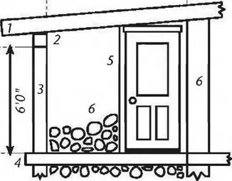
I also drew elevations of all three new sides of the new room, so that I could figure out the windows and door, as well as the post, height. Drawing the extended rafters in scale, and at the correct pitch, showed the post height, and these figures could be checked on site with actual measurements. (Figures 5.4, 5,5 and 5.6). I submitted my plans, along with the $15 fee, to the towns building inspector, and got a permit, an important step.
 The plans also made it easy to generate a materials list, which, in April, I brought to two sawmills for bid. We accepted the slightly higher bid because of quicker and more reliable delivery. This gave the timbers more drying time, and the decision seems to have been a good one, as we have not experienced egregious
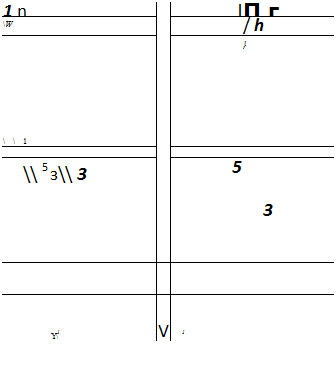
Fig. 5.3: The floor joists for the new room (which are also the ceiling joists for the old one) have four transverse headers to support one end of the short secondary joists. A self-supporting cantilever was not possible at this level in the way that it was for the roof
![]()
![]() rafters.
rafters.
Key:
1 Existing four-by-eight (Ю. І cm – by-20.3 mm) radial joists at Earthwood.
2 Eight-by-eight (20.3 cm-by-
20.3 cm) cedar girts newly installed at top of existing cordwood wall.
3 Replacement four-by-eight joists, married to house joists.
4 Secondary four-by-eight joists cut planking span in half.
5 Headers, all four-by-eights.
6 South wall girts or girders, all eight-by-tens (20.3 cm-by-25.4 cms).
7 Cordwood walls, 16 inches (40.6 cm) thick. Cordwood walls under south-facing windows (see Fig. 5.6) are 8 inches (20.3 cm) thick.
 |
|
|
|
![]()
 |
 |
||
Key:
1 Primary five-by-ten (12.7 cm-by-25.4 cm) rafters
2 Secondary (short) five-by-ten rafters
3 Eight-by-ten (20.3 cm-by-25.4 cm) girts
4 Eight by eight (20.3 cm-by-20.3 cm) posts, six feet long
5 Six-by-eight (15.2 cm-by-20.3 cm) posts, cut at an angle to make the bend in the south wall (See Fig. 5.2)
6 Eight-by-eight cedar girt
7 Existing lower story framework
8 Two-by-six (3.8 cm-by-14.0 cm) tongue-and-groove planking
9 Eight-by-eight beam pieces as snowblocking
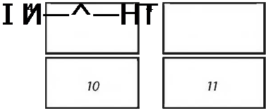
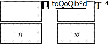
10 42-inch-wide by 48-inch-high (107cm by 122 cm) double-hung windows
11 46-inch-wide by 48-inch-high (117cm by 122cm) double-hung windows
wood shrinkage. The heavy timbers, as listed, cost about $760. This list is given as an example only. Adjustments were made, so it may or may not serve as an accurate materials list to build a similar sunroom. The “purpose” column matters little to the sawyer, but will be helpful to you when you try to figure out what all these pieces are for.
 The flooring and roofing two-by-six tongue-and-groove planks are not included. We needed about 850 board feet of these, which cost us $773.
|
7 1 1 4 1 7 8 6 4 1 2 2 4 |
Timber Schedule for Earthwood Sunroom
(all white pine except as noted)
|
Dimensions |
Length |
|
5" x 10" (12.7×25.4 cm) |
10′ (3 m) |
|
8" x 10" (20.3×25.4 cm) |
12′ (3.6 m) |
|
8" x 10" (20.3×25.4 cm) |
14′ (4.3 m) |
|
8" x 8" (20.3×203 cm) |
14′ (4.3 m) |
|
6" x 8" (15.2 x 20.3 cm) |
14′ (4.3 m) |
|
4" x 8" (10.1 x 20.3 cm) |
10′ (3 m) |
|
4" x 8" (10.1 x 20.3 cm) |
8′ (2.4 m) |
|
1" x6" (2.5 x 15.2 cm) |
8′ (2.4 m) |
|
111 x 10" (2.5×25.4 cm) |
12′ (3.6 m) |
|
Iм x 12" (2.5×30.5 cm) |
10′ (3 m) |
|
2" x 8" (5.1 x 20.3 cm) |
12′ (3.6 m) |
|
(The following pieces shall 1 |
|
|
8" x 8" (20.3 x 20.3 cm) |
10" (3 m) |
|
2" x 8" (5.1 x 20.3 cm) |
8" (2.4 m) |
Purpose
Rafters (2 cut in half)
Main (center) south wall girt
Right and left south wall girts (cut into 2 @ 7′).
Posts (when cut in half)
Posts (when cut in half)
Floor joists (2 cut in half)
Doorframes (1 for lintel, 1 extra)
Cordwood key pieces and other Broaden lower story girders Finish interior of lower story posts South wall window framing n white cedar)
East and west downstairs wall girts West wall window framing
An eraser is one of your most valuable tools. Figure out the structure and jointing details on paper, ahead of time. Erasing and redrawing a few lines at the design stage can save major headaches later on. If you can’t visualize the situation from paper plans, build a scale model, a great way to figure out how things are connected. If you can’t build the model, maybe you shouldn’t try to build the real thing.
I have deliberately described the order of events we followed, because it is typical of any building project, large or small. It all starts with conceptualization of the project, which should involve all of the interested parties. This is followed by more detailed drawings, securing a building permit, and, finally, the pricing and procurement of materials. After all that is done…


Leave a reply