FOUNDATION INVESTIGATIONS AND SOILS ANALYSIS

8.3.1 General Considerations

Since the stability and safety of a structure—more specifically, retaining wall structures— depend upon the proper performance of the foundation, it is important that an adequate foundation investigation be made. The purpose of the investigation is to provide the designer with information concerning the engineering properties of the subsurface condi­tions. Generally, a retaining wall extends for a considerable length. Accordingly, the amount and type of foundation investigation that should be made and/or which the owner can afford must be considered. The owner must understand that once an exploration crew is dispatched to the site of a proposed wall, the investigation should be sufficiently complete to allow for the selection of an appropriate wall type.

When a rigid concrete retaining wall is to be used, the designer must consider that such a wall can tolerate only minimal differential settlement. If differential settlement is predicted, the designer may have to accommodate this situation by vertical joints in the wall and other systems of articulation in the wall. In many instances, this type of wall, under situations where differential or excessive settlement is anticipated, will require deep foundations such as caissons or piling driven to firm supporting material. Alternatively, subexcavation and replacement of poor material at the base of the wall may be appropriate. When a mechanically stabilized wall is selected under conditions of poor foundation soils, the wall is more tolerant to such a foundation condition. It is important for the owner to realize that while the wall is more tolerant to this condition, the end result as viewed from the finished top surface of the wall may be decidedly different. Therefore, it is important for the owner to set out the requirements of, and acceptance criteria for, the wall prior to the selection process. All alternative wall types evaluated should meet those criteria. Otherwise, the owner is not evaluating equal alternatives.

Subsurface Exploration Plan. Retaining walls are often viewed as subsidiary structures not worthy of any substantial expenditure for subsurface exploration. To the contrary, retaining walls can be costly structures. Further, the ultimate cost of most walls is quite sensitive to the foundation material.

The subsurface exploration plan can include obtaining subsurface data through the use of geophysical methods, such as seismic and electrical resistivity methods. More often the subsurface exploration effort is a simple and traditional boring program.

The boring program can be a simple auger drilling program with an experienced geologist classifying the soil on the basis of the auger cuttings. Clearly, if a physical examination of the type, nature, and characteristics of the subsurface materials is
desired, samples will be necessary. The samples can be disturbed or undisturbed. The disturbed sample is generally taken in cohesionless soils and is used for classification and for moisture determination and compaction tests. More commonly, such samples may be taken by driving a heavy walled sampler into a clean hole. The size of the sampler or spoon varies from 2 in (50 mm) O. D. to 4/2 in (112 mm) O. D. When a standard penetration test (SPT) is required, the sample is obtained by driving a 2-in (50 mm) O. D. by 138-in (34 mm) I. D. sampler.

Where it is necessary to evaluate the structural properties of the subsurface material in its natural condition, an undisturbed sample is taken. This type of sample will produce a core sample that can be used for such laboratory tests as the triaxial shear, uncon­fined compression, and consolidation tests. This type of sample is more frequently taken in cohesive soils that contain little or no granular materials. It is often taken with thin-walled tube samplers (Shelby type).

The SPT results may be used to describe soil density and clayey soil consistency as shown in the following table:

Granular soil

Clay

Blows

Density

Blows

Consistency

0-4

Very loose

0-1

Very soft

5-10

Loose

2-4

Soft

11-24

Medium dense

5-8

Medium stiff

25-50

Dense

9-15

Stiff

Over 50

Very dense

16-30

Very stiff

31-60

Hard

Over 60

Very hard

The blows are for the test procedures given in AASHTO Test Designation T-206.

Whenever rock is encountered, core drilling is done to advance the boring and to sample the rock in order to determine the profile and nature of the underlying rock strata. A general method by which the quality of the rock at a site is related to the amount of fracturing and alteration is known as the rock quality designation (RQD). The procedure consists of summing the total length of core recovered by counting only those pieces of hard and sound core that are 4 in or greater in depth. The ratio of this modified core recovery length to the total core run is the RQD. Rock quality is related to the RQD as follows:

Rock quality

designation (RQD) Rock quality

Very poor

Poor

Fair

Good

Excellent

Soil Properties. Soils include matter in three states: solid, liquid, and gas. Figure 8.13 shows a diagram of a soil block and presents the fundamental weight-volume relation­ships among the terms. The following sample problem illustrates application to a soil sample. Refer to Fig. 8.13 for nomenclature.

Soil block

Volumes

Weights

Gas (air)

Vs

W, = 0

Water

Vw

Ww =Vw7w

Solids

Vs

ws =VsYsGs

V = VV + VS = total volume

II

+ VW = volume of voids

W = total weight = V у

V/Vv = Vv/Vv + Vs/Vv or

1/n = 1

+ 1/e and n = e/(1 – n)

e = Vv/Vs = void ratio n =

Vv/V = porosity

whereGS = specific gravity of soil

yw = unit weight of water

yS = unit weight of solids

Y = unit weight of soi

FIGURE 8.13 Weight-volume relationships for soils.

• Data:

Clay sample with water content of 31.2 percent by weight.

Specific gravity of soil particles is 2.80.

Sample is 98 percent saturated.

• Determine void ratio e and soil unit weight y; assume 1 cm3 of solids for calculations; V = 1.00 cm3:

S

V /V = 0.98

W

Ws = 2.80 X 1 g/cm3 = 2.80 g

W = 0.312 X 2.80 = 0.874 g

W = W + W = 2.80 + 0.874 = 3.674 g

Vw = Ww/yw = 0.874 g/(1 g/cm3) = 0.874 cm3

V = V /0.98 = 0.874/0.98 = 0.892 cm3

V w

V = V – V = 0.892 – 0.874 = 0.018 cm3

g V w

V = V + V = 1.00 + 0.892 = 1.892 cm3

S V

e = V/V = 0.892/1.00 = 0.892

vs

y = W/V = 3.674/1.892 = 1.94 g/cm3

. The Case for Not Leveling Trim

The older a house, the less likely its floors and ceilings will be level. So don’t make yourself crazy trying to level baseboards and crown molding: You won’t succeed, and trim that’s level next to a surface that isn’t will only emphasize the discrepancy. Interior trim, like politics, is an art of compromise. Trim edges should be roughly parallel to floors and ceilings. As master carpenter Joseph Beals puts it, "Baseboard is effectively floor trim, and the floor plane is the critical reference, level or not."

Midwall elements such as chair rails, picture rails, and wainscoting call for yet more fudging. Ideally, chair rails should be level and wainscoting stiles (vertical pieces) should be plumb, but those ideals may clash with existing trim that’s neither. In that case, split the difference: Tack up a length of trim that’s level. Then raise or lower one end till your eye accepts the compromise.

Trim can also help give the illusion of a level ceiling-helpful, when upper kitchen cabinets must be set level even if the ceiling isn’t. So after leveling and securing upper cabinets, install a strip of molding to cover the gap above. (You may need to rip it down at an angle.) If you look for it, you’ll see the uneven strip of molding between the cabinets and the ceiling. But if the cover trim matches the cabinet finish, chances are nobody else will notice the difference.

Finish Carpentry Fasteners

FASTENER

USES

COMMENTS

20-gauge brad

Attach small molding returns.

Glue returns first.

18-gauge brad

Tack-nail trim while adjusting; attach cabinet toekicks and side panels.

Tiny brad holes easily filled; easy to pry off tacked trim

4d (11/2-in.) finish nail

Attach inside edge of casing to rough jambs (jambs of rough opening).

Snip nail point if worried about splitting casing.

6d (2-in.) finish nail

Attach outside edge of ‘/i-in.-thick casing (through ‘/i-in. drywall) to rough jambs.

Nail should sink at least ‘/ in. into framing.

8d (21/2-in.) finish nail

Attach outside edge of 3/4-in.-thick casing (through drywall) to rough jambs; attach baseboard; attach crown molding.

Place nails a minimum of 3/ in. from edge; snip nail points to minimize splits.

21/2-in. to

3-in. finish-head

screw

Secure window – or door-frame jambs to rough openings.

Frame jambs twist or flex as doors and windows are operated, so use pairs of screws at each point.

Example of Active Pressure Calculations

The active pressure coefficient Ka is given by Coulomb theory as

where 0 = angle of slope of back wall to horizontal, degrees ф’ = effective angle of internal friction, degrees 8 = angle of wall friction, degrees P = angle of back slope, degrees

Refer to Figure 8.12 for the force diagram. The resultant horizontal earth force is to be determined for a design case wherein the following assumptions apply:

Design assumptions

ф’ = 34°

8 = 25°

P = 0°

0 = 90°

Y = 125 lb/ft3 (19.6 kN/m3)

H = height of wall = 20 ft (6.1 m)

Soil type = 1 (see Table 8.1)

Computations

sin (0 + ф’) = sin (90° + 34°) = sin 124° = 0.8290 sin2 (0 + ф’) = sin2 (90° + 34°) = sin2 124° = 0.6873 sin (ф’ + 8) = sin (34° + 25°) = sin 59° = 0.8572 sin (ф’ – P) = sin (34° – 0°) = sin 34° = 0.5592 sin (0-8) = sin (90° – 25°) = sin 65° = 0.9063 sin (0 + P) = sin (90° + 0°) = sin 90° = 1.0000 sin2 (0) = sin2 (90) = 1.0000

ka = horizontal active pressure = Ka8’H = 0.2542(125)20 = 635.5 lb/ft2 (U. S. Customary units)

= 0.2542 (19.6) 6.1 = 30.4 kPa (SI units)

Pa = force resultant due to horizontal active pressure

Alternate calculation. Figure 8.10 gives the horizontal and vertical components of active earth pressure, kh and kv, for the five soil types listed in Table 8.1. The pres­sures are given in terms of the ratio H1/H, when H1 is the surcharge height and H is the height of the fill from the base, both as defined by the sketches in Fig. 8.10.

From Fig. 8.10, soil is type 1, H1/H = 0, kh = 30 lb/ft2/ft. Use 35 lb/ft2/ft (5.50 kN/m2/m), per note 3, Fig. 8.10.

Pa = /2khH2 = /2 X 35(20)2 = 7000 lb/ft (U. S. Customary units)

= /2 X 5.50(6.1)2 = 102 kN/m (SI units)

ECONOMICAL EFFECTIVENESS

In most countries, SMA mixtures are more expensive to construct than comparable mixtures of AC. Higher initial prices result from the application of the following:

• Larger amounts of binder (or a PMB)

• Greater amounts of added filler

• Large quantities of high quality coarse aggregates

• Stabilizers (most often fibers)

• Higher production temperatures

• Lower outputs of asphalt plants

The approximate price difference amounts to + 20% to + 30%, depending on the country and specificity of the placement. However, such a difference in price is accepted by road administrations owing to the better durability of SMA pavements. It is widely assumed that their average lifetime amounts to at least 20 years. In many countries it is difficult to verify this service life due to the small number of SMA sections that have been in place longer than 15 years.

It can be assumed that the higher initial costs of SMA mixtures have been com­pensated for by their longer durability and lower maintenance costs. Taking into account the lower costs of operation due to the absence of repair needs and hence fewer traffic disruptions for road users, the economical efficiency of SMA is higher than that of the classic AC.

Cut in around the edges

The two basic techniques for painting both ceilings and walls are cutting in and rolling. “Cutting in” means brushing paint onto areas that can’t be reached with a roller. Painters usually begin working from a ladder, cutting in the corners where the ceilings meet the walls. Use a 3-in. or 4-in. brush to make a cut-in band all around the ceilings and walls, as shown in the photo at left. This band will be overlapped when the large open spaces are painted with a roller. Professional painters prefer to use a brush for cutting in, but it can also be done with a paint pad, which is basically just an absorbent sponge on a handle.

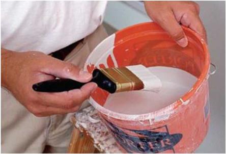
Take your time. Good brushes are easy to load with paint. Rather than painting with a full can of paint, painters like to use a bucket that’s about half full. This allows them to dip the bristles about halfway into the paint, then fill the inner part of the brush with a few gentle slaps of the brush against the inside of the can (see the photo below). Apply paint in relaxed, even, gentle strokes.

Подпись: Newer, light-weight spack- ling products make it easy to fill holes. These products spread easily, dry fast, and need little or no sanding.Use a roller to fill the field

Once you’ve finished cutting in, switch to a roller to paint the rest of the ceilings and walls. Ask at the paint store which roller to use for your type of paint and wall surface. Many painters use a good-quality 9-in. roller frame fitted with a */2-т. synthetic-nap roller. An extension pole that attaches to the frame makes it easy to reach the ceiling. Paint can be loaded on a roller from either a paint pan or from a 5-gal. bucket with a roller screen hooked to the inside. Don’t overload either the pan or the bucket with paint. Dip the roller into the paint several times to saturate the nap. Then unload the excess paint on the pan or roller screen (see the photo below).

Rolling paint on ceilings and walls must be done slowly and methodically, using long strokes. It must be done slowly because push­ing a roller rapidly scatters paint far and wide.

It must be methodical so that every square foot of drywall receives full and equal coverage. Try painting in 3-ft. squares, running the roller back and forth in a tight “M” or “W” forma­tion, with each stroke overlapping the previous one by a few inches. Blend the main ceiling paint into the corners by overlapping the cut-in sections by an inch or so, but be careful not to touch the other side. In hot, dry climates, try to keep the working edge wet with paint. If you overlap a dried edge, you’ll often see a lap mark after the paint has dried.

When rolling paint on walls, you can reduce the splatter by painting on the upstroke. Watch out for paint ridges left at the ends of a roller. Try tipping the roller to the side to squeeze out the excess paint as you roll. Then go back over the ridge and even out the coat. Apply a uniform, thick coat, but not so thick that the paint begins to run. When painting near the floor, turn the bend in the roller frame toward the floor to keep the roller from picking up dust and dirt. With care, you should be able to cover the walls and ceilings with one coat on top of the primer, especially if you’re using good-quality paint. But don’t despair if one coat looks a little
thin. Paint is not all that expensive, so just roll on another coat, if necessary.

CHOOSING AND CARING FOR BRUSHES

CHOOSING AND CARING FOR BRUSHES

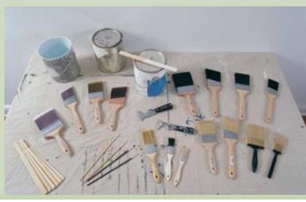
My hand likes the fit of a long-handled brush. But bristles, not handles, are what make a good brush. Brushes with natural bristles, usually hog’s hair, work best with oil-based products. Synthetic-bristle brushes work best with water – based paints. Soft nylon bristles are a good choice for finish work, whereas stiffer poly bristles are better for painting rough or textured surfaces, such as siding. A combination of nylon and poly bristles usually makes a good all-purpose brush. For painting large surfaces, a 3-in. or 4-in. brush with square-cut bristles is a good choice. A 1-in. or 2-in. brush with bristles cut at an angle gives you more control for cutting in trim.

A quality brush can last for years if you take good care of it. That means cleaning it thoroughly each time you use it. First, remove most of the paint from a brush by painting on some cardboard or newspaper. If you’re using oil-based paints, then you must wash the brush in paint thinner. Latex and acrylic paints can be washed in lukewarm soapy water. Once the brush is clean, you can either spin it dry with a

brush spinner (available at most home centers and hardware stores) or just let it dry naturally. A wire brush and a brush comb are good to have on hand for removing hardened paint and straightening the bristles. Finally, once the brush is dry, store it in its wrapper until you need it again.

CHOOSING AND CARING FOR BRUSHES

Подпись: Cut in with a paint brush. A roller can't reach corners and edges. A 3-in.- to 4-in.-wide brush is ideal for painting these areas. [Photo courtesy HFHI] Подпись: Avoid over-loading. Inexperienced painters often make the mistake of overloading brushes (and rollers) with paint. All this does is make a bigger mess, with paint splattering, dripping, and running down to your elbows. Подпись: Load your brush with paint. A good brush can hold plenty of paint. Using a half-full paint bucket allows you to dip and load your brush by tapping it gently against the inside of the bucket.CHOOSING AND CARING FOR BRUSHES

that have dried on the floor. Drywall mud left on the floor can work its way up through a car­pet. Then vacuum up all the dust. Cover the tub or shower with a protective sheet of inexpensive 1-mil plastic, often called painter’s poly, affixed with masking tape.

Apply the prime and finish coats

My advice for buying paint and brushes is the same as for buying any other tools and materials: Talk to contractors and knowledge­able folks working behind the counter where you buy your supplies. Then buy the best you can afford. A knowledgeable paint supplier will help you choose primer and finish paints that are compatible; you’ll also get advice on the best brushes and rollers to use with your paint. For some basic background information, see the sidebar on p. 231. A well-built house deserves a quality paint job. Spending more money on high-quality paint can actually save you money down the road, because good paint covers better and holds up well over time.

When using several gallons of a single color, mix them together in a 5-gal. bucket to ensure uniformity. Keep the pigment mixed by stirring well before painting and throughout the day.

Earth Pressure Calculations

For yielding walls, lateral earth pressures can be computed assuming active conditions and wedge theory, using a planar surface of sliding defined by the Rankine theory. Table 8.1 provides soil properties for computing active earth pressures for five types of soil. Table 8.2 provides friction factors and adhesion for dissimilar materials. See Figs. 8.10 and 8.11 for the magnitude and location of resultant forces on retaining walls considering various types of soil backfill and backslide geometries. The pressures presented in these figures assume mobilization of the soil shear strength along the entire Rankine active failure plane, extending uninterrupted from the ground surface at the base of the wall or to the location on the wall at which the total earth load is being computed. Figure 8.11 shows the failure surface geometry and associated earth pressure distributions for various design conditions. If the soil behind the wall consists of more than one soil type, the design earth pressure should be determined using the weighted average of the properties of the soil types within and along the theoretical failure plane.

AASHTO provides that, for yielding walls, lateral earth pressures should be computed assuming active stress conditions and wedge theory using a planar surface of sliding defined by Coulomb theory. The computational procedures for active pressures are

FIGURE 8.9 Relationship between wall movement and earth pressures. (a) Ideal cases where the backfill begins from at-rest pressures; (b) case for a sand backfill compacted to a medium-dense con­dition with no wall movement. (From Clough, G. W. and Duncan, J. M., “Earth Pressures,” Chap. 6 in Foundation Engineering Handbook, Fang, H. Y., Van Nostrand Reinhold, New York, 1991, with permission)

Soil

type

number

Soil description

uses symbol"

Unit horizontal soil pressure^7 kh, lb/ft2/ft (kN/m3)

Rankine active earth pressure coefficient^ К

a

Total soil unit weight 7, lb/ft3 (kN/m2/m)

Effective angle of friction ф;, 0

1

Sands and gravels with little or no fines

GW, GP, SW, SP (AASHTO A7)

30" (4.7)

0.25

120 (18.8)

37

2

Sands and gravels with some silt

GM-GP, GM-GW, SM-SP, SM-SW

35 (5.5)

0.29

120 (18.8)

33

3

Silty and clayey sands and gravels

GM, GC, SM, SC

45 (7.1)

0.45

100 (15.7)

22

4

NOCrf to LOC’ silts and clays

ML, MH, CL, CH

100 (15.7)

0.80

125 (19.6)

5

HOC/ clays which can become saturated

CL, CH

120 (18.8)

1.00

120 (18.8)

675

"Unified Soil Classification System (see Fig. 8.14).

bAt (3 = 0°, representing a horizontal backslope behind the wall. For a sloping backfill ((3 > 0), refer to Figs. 8.10 and 8.11. kh = Kgy. cThe minimum value of kh for design should be 35 lb/ft3.

^Normally overconsolidated (OCR =1).

^Lightly overconsolidated (OCR = 1 to 2).

^Heavily overconsolidated (OCR >2).

^Undrained shear strength.

Source: From Design Manual, Part 4, Pennsylvania Department of Transportation, Harrisburg, Pa., with permission.

Interface materials

Friction factor, tan 8

Friction

angle 8, °

Mass concrete on the following foundation materials:

Clean sound rock

0.70

35

Clean gravel, gravel-sand mixtures, coarse sand

0.55-0.60

29-31

Clean fine to medium sand, silty medium to coarse

0.45-0.55

24-29

sand, silty or clayey gravel

Clean fine sand, silty or clayey fine to medium sand

0.35-0.45

19-24

Fine sandy silt, nonplastic silt

0.30-0.35

17-19

Very stiff and hard residual or preconsolidated clay

0.40-0.50

22-26

Medium stiff and stiff clay and silty clay

0.30-0.35

17-19

(Masonry on foundation materials has same friction factors.)

Steel sheet piles against the following soils:

Clean gravel, gravel-sand mixtures, well-graded rock fill

0.40

22

with spalls

Clean sand, silty sand-gravel mixture, single-size hard

0.30

17

rock fill

Silty sand, gravel or sand mixed with silt or clay

0.25

14

Fine sandy silt, nonplastic silt

0.20

11

Formed concrete or concrete sheet piling against the following soils:

Clean gravel, gravel-sand mixture, well-graded rock fill

0.40-0.50

22-26

with spalls

Clean sand, silty sand-gravel mixture, single-size hard

0.30-0.40

17-22

rock fill

Silty sand, gravel or sand mixed with silt or clay

0.30

17

Fine sandy silt, nonplastic silt

0.25

14

Various structural materials:

Masonry on masonry, igneous and metamorphic rocks:

Dressed soft rock on dressed soft rock

0.70

35

Dressed hard rock on dressed soft rock

0.65

33

Dressed hard rock on dressed hard rock

0.55

29

Masonry on wood (cross grain)

0.50

26

Steel on steel at sheet pile interlocks

0.30

17

Adhesion

Adhesion

Interface materials*

C, lb/ft2

a’

Ca, kPa

Very soft cohesive soil (0-250 lb/ft2) (0-12 kPa)

0-250

0-12

Soft cohesive soil (250-500 lb/ft2) (12-24 kPa)

250-500

12-24

Medium stiff cohesive soil (500-1000 lb/ft2) (24-48 kPa)

500-750

24-36

Stiff cohesive soil (1000-2000 lb/ft2) (48-96 kPa)

750-950

36-45

Very stiff cohesive soil (2000-4000 lb/ft2) (96-192 kPa)

950-1300

45-62

*Cohesion values are shown in parentheses.

Source: From Design Manual, Part 4, Pennsylvania Department of Transportation, Harrisburg, Pa., with

permission.

2k!H2H

Hi

b

Soil type 1 (see Note 3)

0 0.2 0.4 0.6 0.8 1.0 0 0.2 0.4 0.6 0.8 1.0 0 0.2 0.4 0.6 0.8 1.0

Values of Ratio – H-

FIGURE 8.10 Charts for estimating Rankine active earth pressures against retaining walls support­ing sloped ground of limited height. Notes: (1) Soil types shown on curves correspond to soil types described in Table 8.1. (2) For soil type 5, computations of soil pressure may be based on a value of H 4 ft (1.2 m) less than the actual value. (3) The minimum value of kh for design should be 35 lb/ft2/lin ft (5.50 kN/m2/m). (4) Add pressures due to water and surcharge (including 2 ft minimum soil surcharge) to the active earth pressures from these charts. (From Design Manual, Part 4, Pennsylvania Department of Transportation, Harrisburg, Pa., with permission)

DESIGN FAILURE SURFACE HORIZONTAL EARTH

CONDITION GEOMETRY PRESSURE DISTRIBUTION

LEGEND

kh1 = unit horizontal soil pressure due to backfill kh2 = unit horizontal soil pressure due to in situ soil P = angle between Rankine active failure plane and horizontal ф’ = weighted average effective stress angle of internal friction along failure plane

P = tan-1 tan ф’ + 1 + tan^’———— в

s^’ cosф’

NOTES

(1) Obtain values of kh1, kh2, and vertical component of soil pressure.

(2) The earth pressure resultant for this condition can be more accurately determined by Culmann’s graphical construction.

(3) Add pressures due to water and surcharge (including 2-ft minimum soil surcharge).

FIGURE 8.11 Assumed failure surfaces and horizontal earth pressure distributions. (From Design Manual, Part 4, Pennsylvania Department of Transportation, Harrisburg, Pa., with permission)
given below. An alternative to the computation for active pressures using the Coulomb theory for yielding walls and for cohesionless soils is to define the lateral pressures utilizing the Rankine theory.

The above procedures for developing the design pressures on yielding walls are based on the following assumptions:

1. The backfill soils are compacted with lightweight hand-compaction equipment.

2. The soil within the theoretical failure zone is made up entirely of the backfill soil.

3. No point or line loads act on the backfill surface.

4. The retaining wall deflections are consistent with the deflections required to develop the design active earth pressure.

Installing Headers

A header is a short transverse wooden member used to provide support for an otherwise unsupported joist or rafter. An example is when a roof rafter needs to be cut to make way for a skylight; a header spans between the adjacent rafters to frame the skylight.

The floor joist system for our new room required headers for a different reason. As the radial floor joists get further from the center of the house, they also get

further apart from each other. This increases planking spans until we begin to experience a “springy” floor (deflection), an indication that plank­ing span is being stretched too far.

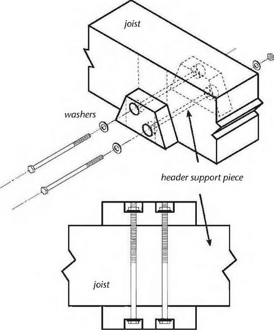
Подпись: Fig. 5.14: We mode ten of these little support pieces very quickly.image121Подпись: 3/8" nuts washersПодпись: 3/8"x 7" lag boltsПодпись: Fig. 5.15: The locations of the header, the header support piece, and the drill holes are all marked on the four-by-eight floor/ceiling joist. We actually used carriage bolts, but countersunk lag bolts could be used as well. Drawing by Doug Kerr. image122The simple solution would have been to run another radial floor joist hallway between the primary ones, cutting all planking spans in half. The problem was that there was an existing cordwood wall, which would have needed rebuilding to make room for one end of the new joists; a lot of work. Besides, planking spans were okay near the round house; they only started to get dicey a few feet away from the main building.
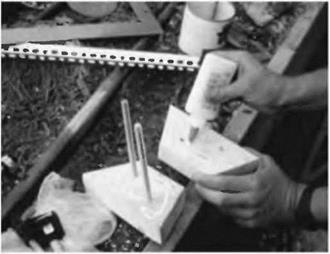
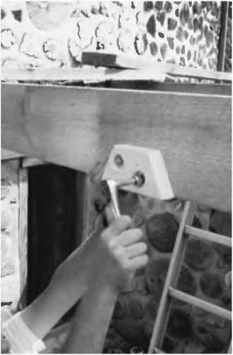
Four headers, as shown in Fig. 5.3, enabled us to support one end of a shorter secondary rafter. The existing girder would support its outermost end. There are two easy ways to fasten the headers: The first is to use metal joist hangers made for the purpose. But we didn’t want to see the galvanized hangers, and besides, our local supplier did not carry them for full-sized four – bys. The second is to use two strong lag bolts — say one-half-inch by eight inches — installed through the side of a joist and into the end grain of the header. Place them about two inches from the top and two inches from the bottom of the members, and centered on the width of the header. This was an attractive idea, but once one header

was installed, it would not be possible to install the next one in the same way — not if I wanted to maintain the symmetry of Fig. 5.3. I thought of offsetting each header by four inches, so that the lag screws could always be driven in, but this spoiled the symmetry and I would still have a problem getting lag screws into the headers where they meet the east and west cordwood walls.

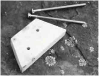
Once again, improvisation saved the day. I came up with a header support system that was attractive (it was made of wood), strong, and could be assembly – lined quite easily. I made ten little trapezoidal header support pieces from a standard two-by-four, each with a base of seven inches (17.8 centimeters) and a top dimension of four inches (10.1 centimeters) to match the four-by-eight headers. I simply marked the two-by-four with my square and made all the cuts quickly with a circular saw. I made ten of the little guys while I was at it, even though only eight were required, in case I spoiled one or two. Fig. 5.14 shows one of the support pieces and a couple of three-eighths-inch by seven-inch carriage bolts, used as fasteners.

On the joists, using a square and pencil, I marked the intended locations where the headers would join in. Using one of my trapezoids as a template, I drew its final position as well, and the location of two carriage bolts that would hold everything together. See Fig. 5.15.

It would have been difficult to hold the two trapezoids in place (one on each side of the joist) while drilling two 7-inch-long holes through all of the pieces, so Doug and I decided to drill just the joist itself with a three-eights-inch bit — that was easy — and then hold the individual trapezoid supports in place and mark their hole locations with either a pencil or by a quick tickle with the tip of the drill. This was a nice two-person job.

Once the two supports were marked, we took them down and finished the holes, being careful to drill as straight as possible. On one of the supports, we used a one-inch spade bit to put a countersink on the outside for the washer and nut. We didn’t want hardware in the way of installing the headers.

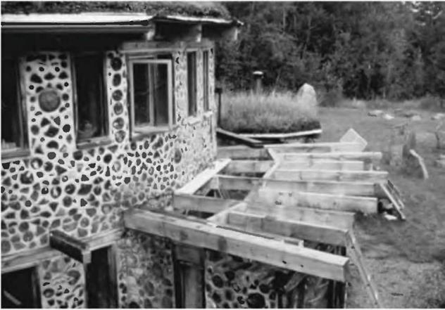
Installation of the header supports was now easy. We glued one side of each piece and inserted the carriage bolt from the non-glued side. Fig. 5.16. This assembly was installed on the joist by tapping the bolts through the three-eights – inch holes. Then the other trapezoid support was installed, glued side against the joist, and the washers and nuts were made fast in the countersink. See Fig. 5.17. The carriage end of the bolt is drawn into the two-by-four, where it will be out of the way of header installation later on.

Подпись: Fig. 5.16, near right: The supports are glued and the carriage bolts installed.
image123

image124Подпись: Fig. 5.17, far right: Doug tightens the hex nut, completing the header support installation.With the supports in place, we’d run slightly long four-by-eight header stock over the top of the joists where it would connect and mark its under­side with a pencil. This eliminated measuring. Using patterns is generally superior to measuring and trying to figure angles. We cut the headers to length with a chainsaw and tried them in place. A good idea in any operation like
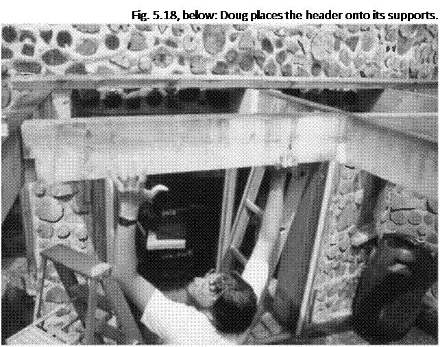
Подпись: Fig. 5.18, below: Doug places the header onto its supports.

this is to always do the longest piece first, it and use it at a shorter location. If you,

If you make a bad cut, you get to re-cut poil the shortest one first, you don’t get a second chance. (“Dagnabbit it! I’ve cut this piece three times and its still too short!” — Old carpenter’s joke.)

If the piece fits, now is the time to cut notches out of each end so that it bears on the header supports. These notches will be 3V2 inches (8.9 centi­meters) high and 1V2 inches (3.8 centi­meters) wide, matching a common store-bought two-by-four stud. If it fits the first time, congratulations! Chances are, though, that you may have to take the piece down and scrape or trim a little to make it fit. Trying and fitting is all part of any kind of timber framing. See Fig. 5.18.

With the headers installed, we can now fasten the secondary joists, the shorter ones whose purpose is to cut the planking span in half Cut one end square, where it will abut the header, and let the other end run long. Always let rough-cut joists and rafters run long on the outside, so that you can snap a chalk-line later and cut them all at one time, all the right length for the

Подпись: Finally, a couple of toenails — from the top, out of sight — will keep the header from wandering. Installing the Secondary Joists Подпись: Fig. 5.19: The floor frame for the new room is completed, and the first two flooring planks are installed.image126overhang. If you cut them the length you think they should be, Mr. Murphys famous law will almost guarantee that you’ll wish you hadn’t. Chalk-lines are like patterns: they are always superior to measuring.

Now is the time to use the simple fastening method alluded to in the previous section. We marked the location of the joist on the header and drilled two seven – sixteenths-inch holes through the wood so that lag screws would meet the end – grain of the joist about two inches from the top and two inches from the bottom—centered right and left, of course. Have someone hold the joist temporarily in place while you tickle its squared end with the drill. Take it down and continue the holes — straight, please — into the end grain of the joist, as deep as is needed for the lag screw used. With a one-half-inch by seven-inch lag screw — plenty strong for the purpose — drill your hole about 23A (7.0 centimeters) inches into the joist. Put a washer under the hex-head of the lag screw and install the bolt. An assistant may have to resist from the other end, to prevent a space occurring between the two members.

Mark and fasten the joist to the girder using one of the methods shown in Figs. 5.12 and 5.13.

The completed floor framework is shown in Fig. 5.19.

Integration of Reliability in Optimal Hydrosystems Design

8.1 Introduction

All hydrosystems engineering problems involve many interconnected and in­terrelated components. The analysis of any hydrosystem problem should take those interactions into account so that the overall behavior of the system is modeled properly. In general, problems in hydrosystems engineering can be classified into (1) development problems, (2) design problems, and (3) opera­tional problems (Buras, 1972). In fact, practically all hydrosystems engineering problems encompass these problem types, which involve activities relating to determination of (1) the optimal scale of development of the project, (2) the op­timal dimensions of the various components of the system, and (3) the optimal operation of the system.

Frequently, design and analysis of hydrosystems involve the use of models. The primary objectives of modeling exercises are (1) to analyze the behavior of existing systems so as to improve their performance and (2) to identify the “best” structural components and configurations of a system under planning. As discussed in Chap. 1, owing to the existence of various uncertainties in hydrosystems modeling, one cannot be certain that the best solution obtained is indeed truly optimal. The conventional approach when facing uncertainties in engineering design is to conduct sensitivity analysis, by which the influences of variation in model parameters subject to uncertainty on the system responses are assessed quantitatively. Simple sensitivity analyses often are ineffective in providing design, management, or operational guidance because when the various system parameters are changed systematically in sensitivity analysis, no consideration is given to whether the changed values are likely or realistic. It is therefore the objective of this chapter to present some practical approaches that integrate the uncertainties and reliability in an optimization framework for hydrosystems design, management, and operation.

Copyright © 2006 by The McGraw-Hill Companies, Inc. Click here for terms of use.

This chapter starts with a brief description of the concepts of some frequently used optimization techniques in hydrosystems engineering design, manage­ment, and operation. More detailed descriptions of the various optimization techniques are given by Mays and Tung (1992), along with several specialized textbooks on the different subject matters. In Sec. 8.2, focus is placed on some typical problems in the context of resource allocation to optimize system reli­ability. Then the concept of risk-based design is described in Sec. 8.3, followed by an example application to hydrosystems engineering in Sec. 8.4. The last two sections, Secs. 8.5 and 8.6, describe a simple way to solve an optimization model in which the parameters are subject to uncertainty.

States of Earth Pressure

Lateral earth pressure loadings are applied in various states—specifically, active, at-rest, and passive states. The state of pressure to be considered varies with the wall type.

Yielding Walls. Yielding walls are free to translate or rotate about their top or base. For such walls, the lateral earth pressure may be computed assuming active conditions and wedge theory. In general, the lateral displacement at the top of a rigid wall of height H necessary to develop the active state varies from 0.001H in dense cohesion­less soils to as much as 0.004H in loose cohesionless soils. For clay soils, a greater displacement on the order of 0.01H to 0.02H, for stiff and soft soils, respectively, is necessary to develop an active state. See Figs. 8.7 and 8.8.

Thus, it is noted that the amount of displacement necessary to develop active pres­sure can vary, say, for a 20-ft-high (6 m) wall, from less than И in (6 mm), in a dense cohesionless material, to as much as 5 in (125 mm), in soft clay. Clearly, the backfill material selected at any location plays a major role in the earth pressure for which a wall must be designed.

Restrained Walls. Restrained walls are walls that are fixed or partially restrained against translation or rotation. Lateral earth pressures are computed assuming at-rest conditions using the following relationship:

P =

P° 2

where P0 = resultant of at-rest earth pressure, kips/ft (N/mm)

7 = unit weight of soil or rock, kips/ft3 (kN/m3)

H = wall height, ft (mm)

K0 = at-rest pressure coefficient

This latter condition may occur naturally at walls that are not totally freestanding—for example, at the junction of the wingwall at bridge abutments—or the condition may occur by design. Examples include locations where the lateral deflection cannot be tolerated because it retains a structure, or a heavily reinforced concrete counterfort wall, which is sensitive to settlement, located on material susceptible to settlement, especially differential settlement. In the latter case the designer must evaluate options that may include, depending upon the depth of the material that will settle, (1) removal and replacement, (2) deep foundations to adequate bearing material, or (3) selection of a different wall type, if conditions permit, that will be more tolerant to the potential for the differential settlement.

Should some force be present that tends to push the wall into the earth mass it is intended to retain—which therefore develops a resistance to slip on the failure plane or a resistance to the lateral displacement needed to mobilize the active pressure state—a condition known as passive pressure develops. The lateral earth pressure for which the wall must be designed increases significantly, as much as 10 times, and requires special attention. See Fig. 8.9 for a qualitative depiction of the relative lateral displacement.

Rigid Walls. For the case of rigid walls, which involves wall translation or rotation “into the backfill,” the movement necessary to develop passive earth pressure behind the wall varies from 0.020H to 0.060H for cohesionless soils, dense to loose, respectively. Also, for stiff to soft cohesive soils, the lateral displacement will vary from 0.020H to 0.040H. It is obvious that passive earth pressures can be developed in these defined con­ditions. Certainly, the best way for the designer to account for these pressures is to avoid them wherever possible and practical, alleviating the conditions under which such pressures develop. This brief discussion is intended only to generate an awareness in the designer that such conditions can be created. An example would be dead-man type anchorages tying the wall top into solid materials or outside the failure plane of the wedge, thus pre­venting the movement necessary for development of the active pressure state.