Flooring (Decking)

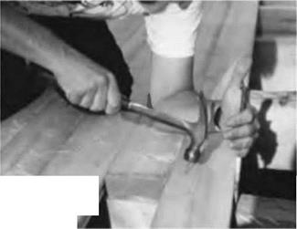
Подпись: Fig. 5.20: Doug draws the new board tight with a long spike, which has had its point driven a little ways into the joist. The spike is now a class 2 lever with tremendous mechanical advantage for drawing tongue-in- groove boards together. Start the nail first. image127We decided on two-by-six V-jointed tongue-and-groove spruce planking for our floor. The V-jointed side goes down, making an attractive ceiling as seen from the room below. We like it for its strength, appearance, and ease of installation. We also like the benefit of doing the floor and ceiling below in one operation, a real plus with the plank-and – beam system. Also, we wanted to maintain visual consistency with the original floor, because there would be a direct doorway opening from the dining room into the new sunroom.
The toughest part of the planking was installing the first board, because it had to be scribed to fit a very rough-textured cordwood masonry wall, as can be seen in Fig. 5.19. Fortunately, the round house was slightly flattened at this point because of a six-foot wide sliding glass door unit below. Still, the first plank had to be scribed with a pencil and cut to fit up against the cordwood wall without huge gaps. I used chisels and a variety of saws to trim the edge that went up against the cordwood wall, the edge with the tongue on it. With new work, especially with conventional rectilinear construction, you will not have this sort of problem. Again, starting from scratch is easier.

Once the first plank was installed, the rest went quite easily. You could hire a machine for blind-nailing tongue-and-groove planking, but I have always used cup-headed nails to attach the planks. These nails can be driven slightly below the surface, so that the floor can be sanded prior to finishing. Use two nails at each place where the plank is supported by a joist, with the nails about an inch inward from both the end of the board and the edge. I insert the tongue of one board into the groove of the board already nailed, then use a ten-inch log cabin spike to draw the tongue absolutely tight into the groove, leaving no space between boards on the top surface. (Remember that the underside has that attractive V-joint, so the boards can only be laid with the non-jomted side up.) While holding the pressure with one hand, I drive the two nails in with the other. You might find it easier to start the nails before drawing the boards up snug. See Fig. 5.20.

With rectilinear buildings, you will want to design the building to maximize the use of the boards. The boards I was able to purchase came only in 12- and 16-
foot lengths. Our floor sections were trapezoidal in shape, so, with our ever- increasing planking span, scrap pieces would constantly get shorter. On subsequent sections, we used the scrap pieces in the reverse order in which they were created. We waited until the first large central section (or facet) was about half covered before cutting the ends. We snapped a chalk-line down the edge of the section, centered over the middle of the four-by-eight joist below. Then I set my circular saw’s blade so that it cut just a little bit deeper than the thickness of the planking, by about one-sixteenth inch (1.6 millimeters). Now I could cut a fair bit of the section at once, and get a nice straight line.

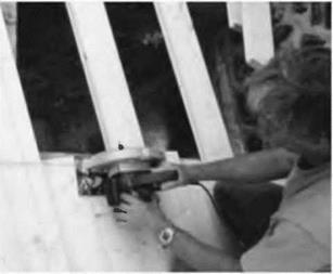
Подпись:image128Подпись: Fig. 5.22: All the important structural members are marked on the deck with a black marker.image129On subsequent facets, it is necessary to trim one end of the board to the proper angle in order to fit it up to the previous section. Use an adjustable angle square to measure and mark this angle. Again, let the extra length of the plank run long, so that all the ends can be trimmed at once. We did this upstairs on the roof planking, and the extra length of the board became the overhang, which was all trimmed at once by a single straight cut with the saw. See Fig. 5.21.

Doug Kerr and I tore out the old deck and joists, installed the new joists, and decked the whole area in just four days, not bad for renovation work. Thanks, Doug!

A Checklist for Choosing a Healthy Mattress

Our homes are places for rest, retreat, and regen­eration. If designed, built, and furnished simply and intelligently, they can help us restore our bal­ance and our connection with nature. For most of us, however, creating a healthy home environment is unfamiliar — and sometimes overwhelming — territory and it is hard to know where to begin. Even if you can’t make every detail in your home healthy, besure your bedroom is as healthyas pos­sible. It’s the most important room in the house. And the most important piece of furniture in the house is your bed, where you spend a third of your life. We are most vulnerable when we sleep. Our bodies let down, shed metabolic waste, and re­group. A healthy, natural, and well-designed mat­tress can provide the right conditions for all the important processes of the body’s natural elec­trical system, internal organs, and subconscious mind to work smoothly and without interference.

Our entire body is in close, direct contact with the materials we sleep in and on. And for eight hours a night we literally inhale, at very close range, whatever is in those materials. Most ordi­nary mattresses are made almost entirely of raw ingredients from the petroleum industry that are made into synthetic components such as visco­elastic and polyurethane foams, including Dacron, whose formulations may contain TDI (toluene dis – carnate, which OSHA labels as a hazardous ma­terial) and other toxic chemicals. To meet federal flammability regulations, they may also contain synthetic chemical fire retardants called organo – phosphates. Mattresses containing natural mate­rials, such as conventional cotton and wool, may also contain pesticide residues. The older a mat­tress gets, the more toxic it becomes if it contains
organophosphate flame-retardants and/or pes­ticide residues because, as the breakdown pro­gresses with age, the rate of release of those toxins increases. They are released as chemical mole­cules that never completely outgas and that bind to house dust, which is then inhaled or ingested. Even mattresses marketed as "natural" may still contain toxic ingredients. Mattress layers can also be held together with glues and their fabrics may be treated with chemicals and harsh dyes. These materials are then wrapped in a quilted surface layer of synthetic fabric stuffed with polyester. These ordinary mattresses trap moisture, dirt, and dust, creating a dust-mite haven that can exacer­bate allergies.

But there’s good news. Thanks to a fast-grow­ing sustainable lifestyle industry, you can now choose beautiful bedding, linens and textiles made from organic natural materials, and com­fortable mattresses that are healthy for the back and for those who suffer from allergies. Here is a checklist of things to consider when buying your new bed.

First, narrow your search by limiting your choices to mattresses made only of high-quality natural components such as pesticide/chemical – free or organic wool, organic cotton, and natural latex, which comes from the rubber tree. Let’s look at each of these components in more depth.

Mattresses and bed systems made with high – quality certified organic wool or locally produced pesticide – and chemical-free wool batting are my preference because both are healthy and highly fire retardant. Since mattresses made without chemical fire retardants still have to pass federally mandated burn tests, you can be sure your fam-

ІІу is safe. Furthermore, wool cushions the joints and muscles, wicks and dries moisture away from the body, and is naturally dust mite resistant, so you don’t need synthetic barrier covers. Since the average body loses about a pint of moisture va­por into the bed every night, it’s important that the battings used in beds and bedding efficiently and effectively wick and dry to eliminate condi­tions favorable for mold and dust mites. Wool is also a temperature and humidity regulator, which means you’ll sleep not only drier but also warmer in the winter and cooler in the summer, even in very humid climates. Except for rare individuals with severe wool allergies, even most people who can’t wear wool clothing have no reaction to wool inside a mattress because it is chemical-free and encased underthe mattress ticking.

Some plusher organic mattresses also con­tain organic cotton batting placed underthe wool layer to keep out dust mites. Organic cotton bat­ting is a much healthier choice for you and the environment than conventional cotton batting because standard cotton is farmed with high lev­els of pesticides and herbicides. Not only is stan­dard cotton a toxic burden for the earth and for farm workers but pesticides residues also can re­main in the cotton batting throughout the manu­facturing process. Even if these residue levels are low, you don’t want to spend eight hours a night with your face next to them.

Natural fabrics such as organic cotton sheet­ing and ticking are free of the chemicals used in conventional fabric manufacturing. Organic fab­rics that are undyed, or dyed with natural and low – impact pigments, are free of the volatile organic compounds (VOCs) that outgas in low levels from conventional fabric finishing, synthetic dyes, and permanent fabric treatments. Natural fabric cov­erings also eliminate a subtle type of electromag­netic field called electrostatic charge. The result is a more healing bed, with natural surfaces that because of the absence of static don’t attract as much dust as synthetic ones.

Natural latex is a comfortable and contour­ing alternative to synthetic memory foams and mattresses imbedded with metal coils. Natural latex mattresses avoid the chemical stew found in typical foam mattresses and need no coils, or innersprings, that might sag or protrude and can prematurely age your mattress. High-quality nat­ural, sustainably produced latex does not sag over time, does not need metal springs to keep its shape, and can offer continuous support for as much as 20 years or longer, depending on the quality of the latex and an individual’s changing support and comfort needs. Make sure that the mattress manufacturer uses only 100 percent nat­ural latex and no synthetic rubber blends.

Second, when choosing your mattress it is im­portant to note that mattresses with metal coifs may pose other challenges for your body. Metal bedsprings (as well as metal bed frames) can act as antennas for human-made frequencies, especially those from FM radio, providing subtle, long-term exposures to a variety of low levels of electromag­netic fields (EMFs). Metal also becomes magne­tized, which may interfere with our bodies’ natural orientation to magnetic north.

Finally, pay special attention to the facility where the bed is made. To avoid cross-contami­nation from other types of materials, your organic bed should be made in a facility that produces

• Coyuchi: Organic cotton bedding

• Eco-terric: Green and healthy furnishings, beds and bedding, and accessories for the home

• Gaiam: Organic bedding and home acces­sories

• Heart of Vermont: Organic futons, mat­tresses, and bedding

• Janice’s: Natural and organic bedding

• Mary Cordaro Collection: Natural,

healthy beds and bedding

• Natural Home: Natural beds and bedding

• Nirvana Safe Haven: Organic and natural beds, bedding, futons, and home accesso­ries for the health-minded and chemically sensitive

Л


only organic beds and bedding, or at the very least isolates its organic facilities from areas where synthetics may be used and does not run any synthetic or conventional fiber or fabric through machines used for organic materials.

Ask if the factory does its own sewing, quilting, and garneting. (Garneting is a mechanical pro­cess whereby short fibers are combed into a spe­cific orientation and formed into thin webs, which are then layered to create the batting used in a mattress.) If the manufacturer tends to outsource these and other steps in the manufacturing pro­cess, the chances greatly increase that your "or­ganic mattress" has been cross-contaminated by synthetic materials in manufacturing plants that make both conventional and organic products.

Find out if the raw materials such as the cot­ton or wool used in your mattress are domestically produced. Transporting them from other coun­tries in containers may add to the cost and will certainly increase the chance that the materials have been exposed to contamination from pesti­cide sprays and other synthetic materials. Long­distance transportation also greatly increases the product’s environmental footprint.

Ask the manufacturer if its mattresses have passed the federal open flame test, certified by a third party, without the use of synthetic materials. Although wool is a very important component, it is not the only ingredient necessary for a mattress
to meet federal flammability regulations. Natural wool, in the right weight and properly garneted, along with correct construction of organic and natural materials, will be an effective fire retardant provided there are no synthetic materials in the mattress.

If the mattress and bedding products are cer­tified with an environmental label, make sure to inquire what that label actually certifies. Check that the certification process includes testing not only for VOCs but also SVOCs, or semi-volatile or­ganic compounds, including pesticides, flame re­tardants, biocides (chemicals that kill bacteria and mold), and plasticizers.

There are many beds on the market today that claim to be made of natural materials and to offer significant health benefits. Because your health and the health of your family are so important, and because you have so many natural beds to choose from, be sure to do your homework and take this checklist with you when you shop for the right mattress.

Mary Cordaro is a certified Building Biology Practi­tioner. She is president and founder of НзЕпуігоп – mental, a healthy bedroom products company, and has been consulting/educating on the healthy home since 1989. Mary is the creator of The Mary Cordaro Collection, a luxury line of healthy, organic beds and bedding. See h3envir0nmentai. com.

Подпись: This bedroom, found in Arizona, provides its owner with an abundance of fresh air! Photo: Robert Laporte.

Sachi Organics: Manufacturers of organic cotton beds and futons and retailers of or­ganic bedding and linens

• Shepherd’s Dream: Custom-made wool mattresses, solid wood bed frames, and or­ganic linens

• Sleeptek Oasis Collection: Custom-made organic mattresses and bedding sets

Further Reading

Leclair, Kim and David Rousseau. Environmental by Design. Hartley and Marks, 1993. Overview of larger environmental concerns related to furni­ture manufacturing

INSTALLINGм SQUARE-CUT DOOR CASING

Few frames are perfectly square, so use a framing square to survey the corners. Note whether a cor­ner is greater or less than 90°, and vary your cuts accordingly when you fine-tune the corner joints. Note, too, whether the floor is level, because side casing usually rests on the floor.

First, rough cut the casing. To determine the length(s) of side casings, measure down from the reveal line on the head frame to the finish floor.

(If finish floors aren’t installed yet, measure down to a scrap of flooring.) Cut the side casings about h in. long so you can fine-tune the joints; then tack the casings to the reveal lines on the side frames. (Use 18-gauge or 20-gauge brads.) Next measure from the outer edges of the side casings to determine the length of the head cas­ing. If the ends of the head casing will be flush to the edges of the side casing, add only h in. to the head-casing measurement for adjustments. But if the head casing will overhang the side casing
slightly—a 14-in. overhang is common if head casing is thicker than side casing—add overhangs to your head-casing measurement. Cut the head casing, place it atop the side casings, and tack it up.

Fine-tuning casing joints. Because you cut the

side casings У in. long, the head casing will be that much higher than the head reveal line. But

image860

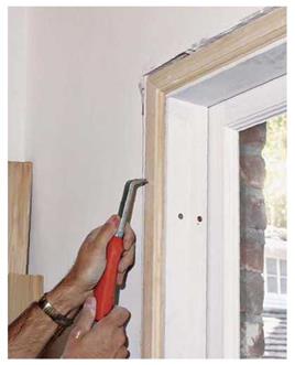
Use a scraper with replaceable carbide blades to shave drywall high spots and hardened joint compound. Use a utility knife to cut back shims still protruding around frames.

image861

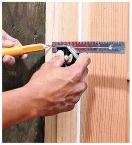
Using a combination square as a marking gauge, make light pencil marks on the jamb edges to indicate casing reveal (offset) lines. By offsetting casing and jamb edges, you avoid the frustrating and usually futile task of trying to keep the edges flush.

image862
INSTALLING SQUARE-CUT DOOR CASING

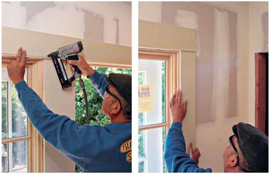
Square-cut head casing can easily span ganged windows or, as shown, a double door with windows on both sides. Here, a carpenter tacked up the door side casings before eyeballing the head casing to be sure the joints were flush.

image863

Use a pin-tacker (brad nailer) to tack the head casing till you’re sure all joints are tight. When that’s done, secure the casing with 6d finish nails.

Slightly back-cut the side casings to ensure a tight fit to the underside of the head casing.

Подпись:

with all casing elements in place, you can see if the head casing butts squarely to the side casings, or if they need to be angle trimmed slightly to make a tight fit. Use a utility knife to mark where the head reveal line hits each side casing, and then remove the side casings and recut them through those knife marks. Retack the side cas­ings to the frame; then reposition the head casing so it sits atop the newly cut side casings. Finally, use a utility knife to indicate final cuts on both ends of the head casing, either flush to the side casing or overhanging slightly, as just discussed.

Gluing joints. Butt joints are particularly prone to spreading, so remove the tacked-up casing, and splice the joints with biscuits, as described earlier in this chapter. Spread glue on all joint surfaces, and nail up the side casing. (Insert bis­cuits, if used.) Draw the head casing tight to the side casing by angle-nailing a single 4d finish nail at each end. To avoid splits, predrill the two nail holes or snip the nails’ points. Then remove excess glue with a damp cloth.

INSTALLING MITERED DOOR CASING

Before installing the casing, first use a framing square to see if the doorway corners are square. If they aren’t, use an adjustable bevel to record the angles and a protractor to help bisect them. Then cut the miter joints out of scrap casing till their angles exactly match the door frame’s. You

Baseboard and Side Casings

SIMPLE BUTT JOINT

image865

image866

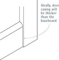
If baseboards are the same thickness as door casings, simply butt them together, or shape the end of the baseboard slightly to reduce its thickness.

can install mitered casing by first cutting the side casing and then the head casing, as you would with square-cut casing. But some carpenters maintain that the best way to match mitered pro­files is to work around the opening. That is, start with one side casing, cut the head casing ends exactly, and finish with the second side casing.

Mark the first piece of the side casing, and

then cut it. After marking a!4-in. reveal around the frame, align a piece of casing stock to a reveal line on a side frame. Where head and jamb reveals intersect in the corner, make a mark on the casing, using a utility knife. (Or make the utility-knife mark!4 in. higher if you’re not confi­dent you can cut the correct angle on the first try.) Miter-cut the top of the side casing so it matches the bisecting angle you worked out earlier on the scrap. Square-cut the bottom of the casing, and tack it to the frame using 18-gauge or 20-gauge brads.

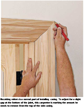
Cut one end of the head casing in the same bisecting angle, leaving the other end long for the time being. Fit the mitered casing ends together, and align the bottom edge of the head casing to the head reveal line. Then, using a utility knife, mark the head casing where side and head reveals intersect in the second corner. You’ll cut through that mark, using the bisecting angle for the second corner (which may be different from the first corners). Again, there’s no shame in recutting, so you may want that utility-knife mark to be in. proud. When its miter is correct, tack up the head casing, and then line up the inside edge of the second side casing to the side reveal line. Use a utility knife to locate its cut­line. Back-cutting miters slightly can make fitting them easier.

Whether you simply glue mitered joints or bis­cuit join them, remove all three pieces of casing before securely nailing them. If biscuit joining, after slotting each piece, reinstall the leg jambs, apply glue and biscuits, and fit the head casing down onto the biscuits. You can use miter clamps or 18-gauge brads to draw the joint together till the glue dries. Be sure to wipe up the excess glue immediately.

Casing a Window

Подпись: Window Trimimage867Подпись: Use 6d or 8d finish nails to attach casing to rough jambs, 4d finish nails to attach the inside edge of casing to frame jambs, and 4d nails to tie the stool to the apron edge.

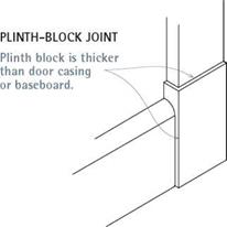
Подпись: Corner-Block Casing Casings with corner blocks are a variation of square-cut casing in which you have seven pieces of trim-two plinth (base) blocks, two cap blocks, two pieces of side casing, and one head casing-to measure, cut, and fit. Start by installing the plinth blocks, which are thicker and wider than the side and head casing. Plinths and cap blocks may line up to reveal lines on door frames, or they may line up with the inside frame edges; be sure to match the detailing of the existing casing. Tack up plinths, using 18-gauge brads. Then measure from the reveal line on the head frame to the top of the plinth blocks to determine the length of side casings. Tack up the side casings, aligning them to the reveal lines on the side frames. Depending on the detailing of the cap blocks, you may need to recut the tops of side casings. Recut the side casing as needed; then tack up the cap blocks and place a spirit level atop them to see if their top edges align and if they're level. Finally, measure between the cap blocks to determine the length of the head casing. (Use a rigid folding rule with a slide-out extension for this task.) If the door frame is slightly out of square, cut the head casing 1/i6 in. to V8 in. long, and back-cut both ends so you can shave them to fit. Once the tack-fit is tight, carefully pry off the tacked up pieces, cut biscuit slots, glue, insert biscuits, reassemble the pieces, and finish- nail the assembly. Glue all joints even if you don't use biscuits.

The casing of windows is essentially the same as the casing of doors, so review earlier sections about prepping frames and installing casing. The main difference is that the side casing of win­dows stands on a window stool, rather than on the floor. Consequently, most of this section

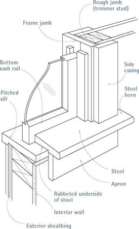
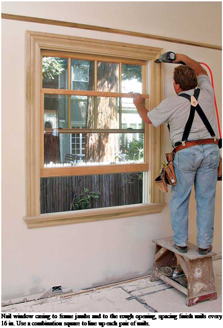
Подпись: Nail window casing to frame jambs and to the rough opening, spacing finish nails every 16 in. Use a combination square to line up each pair of nails. describes measuring and cutting the stool, which covers the inside of a windowsill, and the apron beneath the stool. Sills and stools vary, as described in "Windowsills, Stools, and Aprons,” on the facing page. The following text focuses on installing replacement stools appropriate to older windows.

MARKING THE WINDOW STOOL

Before you start, decide how far the stool "horns” will extend beyond the side casings and how far the interior edge of the stool will protrude into the room. Typically, horns extend И in. beyond ЗИ-in.-wide side casings, but use the existing casings as your guide.

To determine the overall length of the stool, mark И-in. reveals along both sides of the frame jambs. Then measure out from those reveals the width of side casings plus the amount that the stool horns will extend beyond that casing. Make light pencil marks on the drywall or plaster. Rough – cut a piece of stool stock slightly longer than the distance between the outermost pencil marks.

Next, hold the stool stock against the inside edge of the windowsill, centered left to right in the window opening. Using a combination square, transfer the width of the window frame, from the inside of one jamb to the other, to the stool stock. Use a jigsaw to cut along both squared lines, stopping when the sawblade reaches the square shoulder in the underside of the stool. So you’ll know when you’ve reached that shoulder, lightly pencil the width of the shoulder onto the top of the stool, using a combination square as a marking gauge. Next, cut in from each end of the stock to create the stool horns. Carefully guide your saw along the shoulder lines, being careful to stay on the waste side of the line. Clean up cut­lines with a chisel, if needed.

The cutout section of the stool should now fit tightly between the frame jambs. Now, rip down the rabbeted edge of the stool so that it will be snug against the window sash, and the stool horns will be flush to the wall (and jamb edges). Push the stool in till it touches the bottom of the sash, and then pull the stool back Иб in. from the sash to allow for the thickness of paint to come. Finally, measure the distance between the stool horns and the wall, which is the amount to reduce the width of the stool, along the rabbeted edge.

Use a table saw to rip down the width of the stool, then test-fit it again. If it is parallel to (but Иб in. back from) the sash rail, you are ready to cut each horn to its final length. If your stool is flat stock, that’s the last step. But if the stool is molded (has a shaped profile), miter returns to hide the end grain of the horns, as shown in the photo on p. 414.

Sliding Stability

To provide adequate resistance against sliding, the base of the wall should be at least 3 ft below ground surface in front and below the depth of frost action, depth of seasonal volume change, and depth of scour. Sliding stability should be adequate without including passive pressure at the toe. If insufficient sliding resistance is available, the designer may increase base width, provide a pile foundation, or lower the base of the wall and consider passive resistance below frost depth. If the wall is supported on rock or very stiff clay, a key may be installed below the foundation to provide additional resistance to sliding. Considerations of the need for the 3-ft depth when dealing with Reinforced Earth walls should be evaluated in that such walls are not as susceptible to frost action as more rigid concrete walls. In any event, it is recommended that some nominal depth below ground line be provided to accommodate changes in natural terrain over the anticipated life of the structure, often 75 to 100 years. Such changes occur as a result of normal soil erosion caused by wind, rainfall, and other natural processes. Of course, in situations where scour may occur, hydrologic and hydraulic evaluations of scour depth must be made.

8.4.2 Settlement and Overturning

For walls on relatively incompressible foundations, apply the overturning criteria of Fig. 8.21. If the foundation is compressible, compute settlement by available methods pre­viously referred to and estimate tilt of a rigid wall from the settlement. If the consequent tilt is anticipated to exceed acceptable limits, proportion the wall to keep the resultant force at the middle third of the base. If a wall settles so that the resulting movement forces it into the soil it supports, then the lateral pressure on the active side increases sub­stantially. Table 8.3 shows the magnitudes of wall rotation required to mobilize active and passive earth pressures for different types of soil.

Mitigation Methods

The implementation of mitigation and prevention measures from roads and road traffic should follow the pollutant fate in the environment. Before planning and designing of protection against pollutants from road and road traffic, a conceptual model of the pollutant fate in the particular environment should be established. This should help to estimate potential risks and hazards to water bodies’ pollution. The model usually consist of three main parts that are represented by definition of pollu­tant sources, pathways of pollutants through the environment and targets that receive pollution from the sources in road environment. The concept of pollutant fate in the environment is described in greater detail in Chapter 6.

As in every environmentally-driven decision, care must be taken that the ben­efit to the water body is not offset by an equal or worse disbenefit to another environmental compartment. For example, the higher fuel consumption of cars using a longer road could be evaluated in terms of non-renewable energy impact and

Table 12.1 Classification of pollution mitigation approaches and methods

Mitigation approach

Mitigation method

Ex – situ

In – situ

Mitigation at Source

Prevention

Prevention

Avoidance

Reduction

Mitigation along Pathway

Reorientation

Interception

Reduction at Target

Compensation

Remediation

greenhouse gas emissions and these compared with the lower risk achieved to the groundwater. How to make such a comparison is beyond the scope of this book, but interested readers are referred to (Falcocchio, 2004).

It will never be possible to prevent all deleterious impacts of the road on the hydro-environment. However, there are many actions that can be taken to signifi­cantly reduce impacts. In general, the pollution management policy is that protection of the environment should be preformed in a way that the source concentrations of contaminants are reduced as much as possible and to limit, or prevent completely, the appearance of contaminants in the targets. To reach this goal several mitigation approaches and mitigation methods can be adopted (Table 12.1).

Mitigation approaches are divided according to the pollutant fate model: source – pathway – target.

Mitigation at source can be performed with:

• prevention methods;

• avoidance methods; and

• reduction methods.

Prevention methods are in general applied to stop emissions of pollutants in the environment or at particular environmental sensitive areas (e. g. on Natura 2000 areas of sensitive water habitat). A typical general prevention approach is banning of leaded fuel or banning the use of road de-icing agents on the environmental sensitive areas.

Avoidance methods, in general, can be defined as special design proce­dures, mainly connected with road alignment, that avoid crossing envi­ronmentally sensitive areas. They seek to prevent a problem from arising in the first place (or minimize the problem). Often these design options are very costly and they very often interfere with the goals of the road. For example, a road may be longer in order to avoid a particularly sensitive groundwater body leading to greater construction costs and ongoing fuel consumption costs.

Reduction methods are those that are implemented when emissions from roads and the road environment cannot be stopped. They can be im­plemented by various traffic restrictions such as travel velocity reduc­tions (e. g. on groundwater safe-guard zones) or reduction of traffic flow (e. g. embargo of dangerous goods transport over environmentally sensitive areas). Also, among reduction methods, the proper selection of construc­tion materials can be included (e. g. alternative material use for sub-grade that do not interact with the soil environment).

Mitigation along the pathways can be achieved with

• interception methods; and

• reorientation methods.

Reorientation methods divert water that was polluted at the road surface, or inside the pavement, out of the area sensitive to water pollution perhaps to runoff treatment facilities where water is intercepted and treated. A watertight drainage system that diverts runoff water is a typical example of this.

Interception methods are technical measures that enable interception of pollutant flux. These interceptions can be defined as run-off treatment fa­cilities (e. g. detention ponds) or absorption barriers (e. g. reactive barriers).

Mitigation at the target is achieved when pollutant reaches the target and its dele­terious impact is reduced by

• remediation methods; and

• compensation methods.

Remediation methods are only feasible when some deleterious and adverse effects appear at an environmental target (e. g. damage to local fish habi­tat as the consequence of leakage from alternative material built into a sub-base). A typical remediation method in the pavement and embank­ment domain could be the replacement of contaminated granular base and sub-base materials by earth works. These methods would be extreme and only used in situations when previous mitigation measures were not successful. The use of these methods should not be implemented as an integral method for permanent pollution protection. However, in environ­mentally sensitive areas they could be planned as a part of the intervention measures.

Compensation methods are economic measures or replacement measures. The latter are applied in the case that road construction, and all the conse­quences of it, damage a particular habitat or water body. In this case a new, substitute, habitat or water body is included as part of the construction cost in the area where previously the zone was of lower ecological value. As an economic measure, compensation methods are applied as indem­nity to the owners of the land crossed by the road or who are influenced by it. From the environmental point of view, compensation methods for pollution mitigation should be avoided. This approach implements the principle that loss of environmental values can be compensated by eco­nomic measures. Remediation and compensation mitigation methods are usually applied outside of the embankment zone, so they are not covered in full detail here.

Mitigation methods can be further divided into:

• ex-situ methods. Ex-situ methods are implemented externally as non – technical measures or as technical measures performed in places that are not part of the near-road environment.

• in-situ methods. In-situ methods can be defined as mitigation methods imple­mented on the road or in the near vicinity. These methods are further divided into:

o intervention measures, о non-intervention measures.

Intervention measures are those that involve intervention by human action, either when a problem is detected or on a regular basis (e. g. to maintain a pumping system). Active approaches are the least desirable for a number of reasons:

• Their success depends on continued human attention… which is often dif­ficult to guarantee;

• They continue to require funding after construction, both in terms of pay­ment to the personnel involved and, in many cases, in terms of the running costs of electrical or other energy consuming equipment. In the future there may be pressure on funding and a lack of appreciation of a problem that is in focus at the present time. This can lead to less attention at some future date than is necessary; and

• Detection of a problem is necessary in many cases for the active approach to be implemented. Some problems will be readily detected – e. g. those resulting from a spillage during a traffic accident – but many will not be easily detectable in which case it is difficult to incentivize the search for a problem which could conceivably (but probably doesn’t) exist.

Non-intervention measures rely on the installation of some constructed element that continues to function over a large part, or all, of the life of the project in which it is installed. They are often more costly than active ones if expenditure is only considered over a year or two. However, in the long term the ongoing costs of providing active control will usually make passive approaches seem more economic.

The constructed element is designed to achieve one or more of the following:

• that any actual or potential contamination pathway is blocked;

• that there is a purpose-installed receptor for the any potential or actual contami­nant that will prevent the contaminant from reaching a natural receptor to which it would present a hazard; and

• that the water regime adjacent to the road is maintained in an acceptable manner.

It is always best to attempt to avoid pollution problems rather than to intervene

after the event. Data published by the UK’s Highways Agency (2006) for 5 British

roads reveals the high variability of success of different techniques. Sometimes 99%

reduction in contaminant concentration was achieved, sometimes there was even an increase in concentration after use of a “clean-up” technique due, presumably, to remobilization of previously arrested contaminant.

12.2 Conclusions

No road construction can ever have a zero impact on the environment in which it is placed. The materials of which it is constructed will yield a different response to the hydrological situation than did the soils that they have replaced. The con­struction interrupts the preceding natural flow regime (Fig. 12.3). The traffic on the road generates various pollutants that fall on the road (Chapter 6, Section 6.2). For these reasons the road designer must assess the potential impact of each aspect, compute the risk of unacceptable pollution and put in place mitigation measures that will address each unacceptable risk in a technically and economically satisfactory manner – this is a major challenge, especially as regulatory regimes become more and more demanding.

General framework of optimization models

Optimization models possess algorithms to compare the measures of effective­ness of a system and attempt to yield the optimal solution having the most de­sirable value of the adopted measures. In other words, an optimization model applies an optimum-seeking algorithm, which enables the search of all alterna­tive solutions to select the best one. The general class of such optimum-seeking algorithms is called mathematical programming, which includes linear pro­gramming, nonlinear programming, dynamic programming, etc.

The main advantage of optimization models is that the optimal solution to a multidimensional (or multivariate) problem can be found readily by using an efficient search algorithm. The limitation, generally dictated by the solution technique available for model solving, is that sometimes drastic simplifications of real-life systems are inevitable in order to make the model mathematically tractable. Consequently, it is important to recognize that the optimal solution so derived is for a rather restricted case; that is, the solution is optimal to the simplified problem, and it is the optimal solution to the real-life problem of interest only to the extent that the simplifications are not damaging.

All optimization models consist of three basic elements: (1) decision variables and parameters, (2) constraints, and (3) objective functions. Decision variables are those unknown variables which are to be determined from the solution of the model, whereas parameters describe the characteristics of the system. De­cision variables generally are controllable, whereas model parameters may or may not be controllable in real-life problems. Constraints describe the physical, economical, legal, and other limitations of the system expressed in mathemat­ical form. The constraints must be included in the model, if they exist, to limit the decision variables to their feasible values. Objective functions are measures ofthe effectiveness ofsystem performance and are also expressed as mathemat­ical functions of decision variables. In a mathematical programming model, the value of the objective function is to be optimized.

The general form of an optimization model can be expressed as

Optimize

xo = f (x1, x2, …, xn)

(8.1a)

Subject to

gi (x1, x2,…, xn) = 0 i = 1,2, ..

., m

(8.1b)

aj < xj < bj j = 1,2,…, n

(8.1c)

where f (■) and g( ) are, respectively, the general expressions for the objective function and constraint equations, which can be linear or nonlinear. The con­straint set by Eq. (8.1c) is called the bounding constraint, indicating that the decision variables Xj’s are bounded by their respective lower bound aj and upper bound bj. The most commonly seen bounding constraint type is the nonnega­tivity constraint, with the lower bound being 0 and upper bound being infinity.

In the preceding formulation, the decision variables xj’s in the problem gen­erally are controllable inputs. The solution to the problem consists a set of de­cision variables in the system, each of which has a particular value. A solution can be feasible or infeasible. A feasible solution to an optimization problem is the one that satisfies all system constraints simultaneously. That is, a feasible solution is an element in the feasible solution space defined by the constraint equations. The solution to an optimization problem is the one in the feasible solution space that yields the most desirable objective function value, which is called the optimum feasible solution or simply the optimum solution.

The feasible solution space to an optimization model can be classified as ei­ther convex or nonconvex. Schematic sketches of convex and nonconvex feasible solution spaces are shown in Fig. 8.1. The nature of convexity of the feasible region of an optimization problem would dictate whether the optimal solution obtained is a global optimum or a local optimum. A global optimum is the best solution to the problem within the entire feasible space, whereas a local opti­mum is the best solution to the problem in the neighborhood of the solution point.

RIGID RETAINING WALLS

8.4.1 General Criteria

Rigid retaining walls are those that develop lateral resistance primarily from their own weight. Figure 8.20 shows the terms used in the design of this type of wall. On the basis of their overall cross-sections, those walls may be referred to as L walls or T walls. (See insets, Fig. 8.3.)

Pennsylvania Department of Transportation, Harrisburg, Pa., with permission)

Examples of rigid structures typically include concrete gravity walls, thick concrete slurry walls, and gabion walls. Additionally, some Reinforced Earth walls, if designed to be reinforced in such a way that limited lateral movement will occur, can also be categorized as rigid walls. In fact, a wall may have considerable flexibility in its vertical dimension and nevertheless be classified and designed as a “rigid” wall system. Requirements for resistance of these wall types include sliding stability, overturning, bearing pressure evaluation, and settlement considerations. Design criteria for rigid retaining walls are summarized in Fig. 8.21. Overall, or global, stability is an important consideration in that, while the wall itself may adequately retain a soil mass, the soil mass may be unstable because, for example, of a deep-seated failure plane. This type of consideration is evaluated by slip circle analysis.

Economic Considerations

During the planning, construction, operation and maintenance of roads, economics plays an important role with pollution mitigation measures providing constraints that have a significant influence on the final cost of the road and its operation. Water protection measurements can represent an important proportion of the total road cost. For example, in Slovenia (a country in which groundwater is a very valuable resource) it was estimated that, over the groundwater sensitive areas, the protection costs represent between 10 and 50% of the total road construction costs.

Roads are constructed due to socio-economic demands and local communication needs. They are among the most important infrastructure objects provided by soci­ety’s development. Therefore, it often happens that environmental criteria for their construction and operation take second place to the construction criteria, especially in transition economies. During planning and construction, costs for environmental protection measures are very often treated as direct expenses that cause an unjusti­fied rise in the price of the road. Consequently, it can happen that removing these measures is seen to be a source of savings in the project. Damage to the water environment caused by road construction and operation can be very difficult to eval­uate in terms of cost and revenues. However, experience shows that indirect costs caused by incorrect (or omitted) protection measures, although difficult to measure, are very high with long term consequences that can be very difficult to remediate. Roads across drinking water ‘safe-guard’ zones are a particular example illustrating the high costs or high impact that may occur.

A very important economic dimension of protection measures is their operational cost. These costs can represent a large proportion of the total cost of the ongoing road maintenance. Protection measures have to be properly maintained – especially active ones where the run-off is treated before being released to the wider envi­ronment. The high operational cost of some run-off treatment systems can lead to incorrect or incomplete maintenance and, consequently, in the generation of a new pollution point at the treatment outlet. Therefore, run-off treatment systems should be carefully designed and costed for all the potential problems that could occur during the maintenance processes.

Fill holes and gaps

Once the trim has been installed, the next step is to set all the nails, then fill and sand the nail holes. Any nails that are above the surface of the wood must be driven below the surface with a nail set (see the photo at left). If you plan to stain or polyurethane the trim, fill the holes with matching wood putty. For paint prep, you can use painter’s putty or ordinary Spackle® applied with a small putty knife or your finger.

Подпись:Подпись: Fill any gaps with caulk. Before painting the trim, use latex caulk to fill any gaps between the trim and the wall. After applying the caulk with a caulking gun, use a damp rag to smooth the joint.Sometimes the miter joints (where the door and window trim meet) are not tight so you need to fill the gaps. There also may be slight gaps between the wall and sections of door and window casing or baseboard trim. In addition, check for gaps between shelving and walls and around cabinets and other built-ins. All these gaps can be filled with latex caulk, which is paintable and has enough elasticity to move as wood trim expands and contracts with changes in temperature (see the photo below). Wipe off any excess caulk with a damp cloth.

Fill holes and gaps

Подпись:Before painting any trim that has been nailed in place, take the time to remove all the doors and cover the cabinets with paper and painter’s masking tape. I like to use what is called painter’s tape, because it pulls off easily and doesn’t leave a glue residue. Cover fin­ished floors with a paint-absorbing drop cloth. Unscrew the hinges from the door jambs and store them in a box or plastic bag. Some people paint the trim with the same paint they use on the walls. In that case, there are no cutting – in problems between the wall and the trim. However, you may want to use semigloss paint on the trim and doors or semigloss on the trim
and gloss on the doors. Surfaces that are fin­ished with semigloss and gloss are more stain – resistant and easier to wipe clean than flat-finish surfaces. In addition, higher-gloss paint sets off the trim nicely.

Whichever kind of paint you choose, learn to trust yourself with a brush rather than masking between trim and wall surfaces. Masking a wall when painting the trim can be a disaster. When you remove the tape, you could also very easily remove new paint.

Instead of masking off, try using the dry­brush method when cutting in. Dip about one-third of the bristles in the paint, then wipe one side of the brush on the lip of the paint container. Place the dry side of the brush toward the surface that will not be painted and draw a straight “cut” line. Even if you get a little trim paint on the wall, all you have to do is touch up the wall. If a little bit of wall paint gets on the trim at that point, just repaint the trim.

­Finishing Tips

Details on stripping trim, prep work, stains, dear finishes, and paints are given in Chapter 18. Here’s a handful of additional tips:

► Most trim stock comes smooth enough to paint or stain. If you find rough spots, sand them with 120-grit to 180-grit sandpaper before finishing. If molding has only a few rough spots, wrap sandpaper around a block for flat trim or use a sanding sponge for shaped stock. Use a palm sander or an orbital sander on flat trim with a lot of rough spots.

► If you apply a first coat of finish or paint to the trim before installing it, you won’t need to worry about getting finish on painted walls and ceilings. Cut and attach the trim, sand and fill joints as needed, sink nail heads, fill holes with crayon putty, and lightly final sand. Apply the final coat in place, using long brushstrokes to achieve a smooth finish.

► After cutting prefinished trim, wipe sawblades with solvent to clean them.

► If you decide to finish the trim in place, tape 12-in.-wide masking paper to the area around the trim. When the finish is dry, peel off the masking paper.

► Use wax crayon putty to fill holes in prefinished trim. Avoid wood fillers because their solvent can partially dissolve the finish. However, if the wood is unfinished, apply filler before staining it. Filler can be stained and sanded, but be sure to test the colors on scrap blocks first.

► Use the smallest possible brads or nails to attach the trim, and you’ll have less to fill. On dark wood, brad holes are almost invisible.

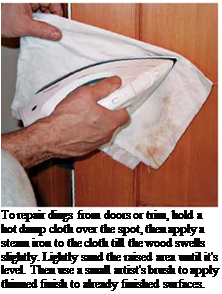
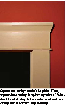
Подпись: To repair dings from doors or trim, hold a hot damp cloth over the spot, then apply a steam iron to the cloth till the wood swells slightly. Lightly sand the raised area until it's level. Then use a small artist's brush to apply thinned finish to already finished surfaces. Подпись: Square-cut casing needn't be plain. Here, square door casing is spiced up with a ’A-in.-thick beaded strip between the head and side casing and a beveled cap molding.

ing profiles as they converge at a corner; square cut, made with basic butt joints; and corner block, a variation of square cut with discrete blocks at the top corners and sometimes bottom corners as well. (Bottom corner blocks are also called plinths. Top corner blocks are called caps.)

PREPPING THE FRAME

Frame edges should extend no more than Zu in. beyond finish surfaces. If they protrude more, sink any nails, and then plane down the frame. If frame edges are level or, say, Уїв in. below the wall surfaces, leave them alone. If the edges are sunk more than that, build them up with shim strips ripped from stock of the same thickness. Scrape the old frame so that it’s flat, glue on the strips, tack with brads if you like, and wipe up the excess glue at once. Also survey the walls around the frame, scraping down globs of joint com­pound or hammering down (compressing) high drywall spots that would make the trim cockeyed.

MARKING A REVEAL

Boards are rarely perfectly straight, and frame jambs and casing stock are no exception. So instead of trying to nail board edges flush, set the inside edge of casings back ‘/ in. from the frame edges. This setback is called a reveal: It looks good and will spare you a lot of frustration. Use the rule of your combination square as a depth gauge. Set the rule to І4 in., and slide along the edge of the frame, making pencil marks as you go. Where head reveals intersect with side reveals, mark the corners carefully.