Installing Headers
A header is a short transverse wooden member used to provide support for an otherwise unsupported joist or rafter. An example is when a roof rafter needs to be cut to make way for a skylight; a header spans between the adjacent rafters to frame the skylight.
The floor joist system for our new room required headers for a different reason. As the radial floor joists get further from the center of the house, they also get
further apart from each other. This increases planking spans until we begin to experience a “springy” floor (deflection), an indication that planking span is being stretched too far.



 The simple solution would have been to run another radial floor joist hallway between the primary ones, cutting all planking spans in half. The problem was that there was an existing cordwood wall, which would have needed rebuilding to make room for one end of the new joists; a lot of work. Besides, planking spans were okay near the round house; they only started to get dicey a few feet away from the main building.
Four headers, as shown in Fig. 5.3, enabled us to support one end of a shorter secondary rafter. The existing girder would support its outermost end. There are two easy ways to fasten the headers: The first is to use metal joist hangers made for the purpose. But we didn’t want to see the galvanized hangers, and besides, our local supplier did not carry them for full-sized four – bys. The second is to use two strong lag bolts — say one-half-inch by eight inches — installed through the side of a joist and into the end grain of the header. Place them about two inches from the top and two inches from the bottom of the members, and centered on the width of the header. This was an attractive idea, but once one header
was installed, it would not be possible to install the next one in the same way — not if I wanted to maintain the symmetry of Fig. 5.3. I thought of offsetting each header by four inches, so that the lag screws could always be driven in, but this spoiled the symmetry and I would still have a problem getting lag screws into the headers where they meet the east and west cordwood walls.
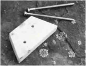
Once again, improvisation saved the day. I came up with a header support system that was attractive (it was made of wood), strong, and could be assembly – lined quite easily. I made ten little trapezoidal header support pieces from a standard two-by-four, each with a base of seven inches (17.8 centimeters) and a top dimension of four inches (10.1 centimeters) to match the four-by-eight headers. I simply marked the two-by-four with my square and made all the cuts quickly with a circular saw. I made ten of the little guys while I was at it, even though only eight were required, in case I spoiled one or two. Fig. 5.14 shows one of the support pieces and a couple of three-eighths-inch by seven-inch carriage bolts, used as fasteners.
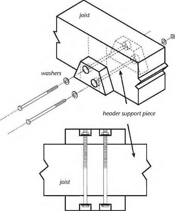
On the joists, using a square and pencil, I marked the intended locations where the headers would join in. Using one of my trapezoids as a template, I drew its final position as well, and the location of two carriage bolts that would hold everything together. See Fig. 5.15.
It would have been difficult to hold the two trapezoids in place (one on each side of the joist) while drilling two 7-inch-long holes through all of the pieces, so Doug and I decided to drill just the joist itself with a three-eights-inch bit — that was easy — and then hold the individual trapezoid supports in place and mark their hole locations with either a pencil or by a quick tickle with the tip of the drill. This was a nice two-person job.
Once the two supports were marked, we took them down and finished the holes, being careful to drill as straight as possible. On one of the supports, we used a one-inch spade bit to put a countersink on the outside for the washer and nut. We didn’t want hardware in the way of installing the headers.
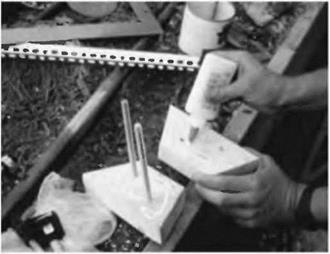
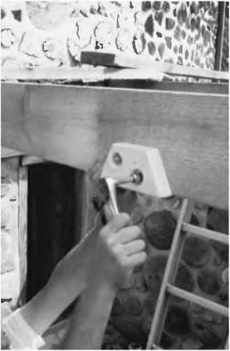
Installation of the header supports was now easy. We glued one side of each piece and inserted the carriage bolt from the non-glued side. Fig. 5.16. This assembly was installed on the joist by tapping the bolts through the three-eights – inch holes. Then the other trapezoid support was installed, glued side against the joist, and the washers and nuts were made fast in the countersink. See Fig. 5.17. The carriage end of the bolt is drawn into the two-by-four, where it will be out of the way of header installation later on.
 |
 |
 With the supports in place, we’d run slightly long four-by-eight header stock over the top of the joists where it would connect and mark its underside with a pencil. This eliminated measuring. Using patterns is generally superior to measuring and trying to figure angles. We cut the headers to length with a chainsaw and tried them in place. A good idea in any operation like
this is to always do the longest piece first, it and use it at a shorter location. If you,
If you make a bad cut, you get to re-cut poil the shortest one first, you don’t get a second chance. (“Dagnabbit it! I’ve cut this piece three times and its still too short!” — Old carpenter’s joke.)
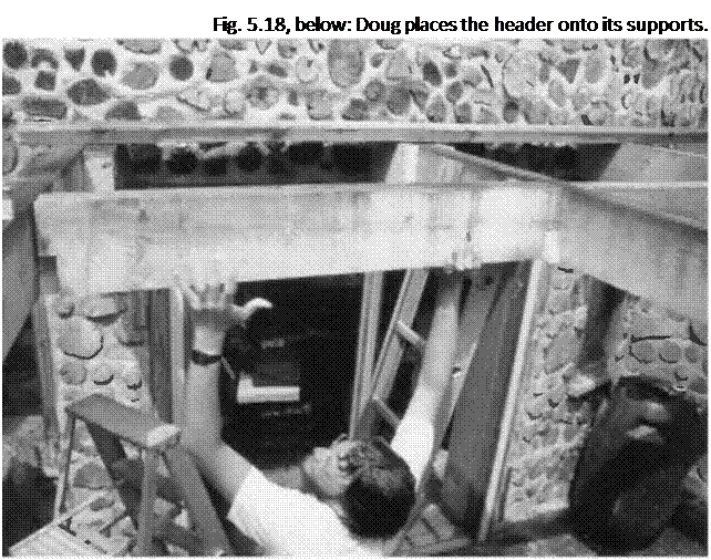
If the piece fits, now is the time to cut notches out of each end so that it bears on the header supports. These notches will be 3V2 inches (8.9 centimeters) high and 1V2 inches (3.8 centimeters) wide, matching a common store-bought two-by-four stud. If it fits the first time, congratulations! Chances are, though, that you may have to take the piece down and scrape or trim a little to make it fit. Trying and fitting is all part of any kind of timber framing. See Fig. 5.18.
With the headers installed, we can now fasten the secondary joists, the shorter ones whose purpose is to cut the planking span in half Cut one end square, where it will abut the header, and let the other end run long. Always let rough-cut joists and rafters run long on the outside, so that you can snap a chalk-line later and cut them all at one time, all the right length for the
 overhang. If you cut them the length you think they should be, Mr. Murphys famous law will almost guarantee that you’ll wish you hadn’t. Chalk-lines are like patterns: they are always superior to measuring.
Now is the time to use the simple fastening method alluded to in the previous section. We marked the location of the joist on the header and drilled two seven – sixteenths-inch holes through the wood so that lag screws would meet the end – grain of the joist about two inches from the top and two inches from the bottom—centered right and left, of course. Have someone hold the joist temporarily in place while you tickle its squared end with the drill. Take it down and continue the holes — straight, please — into the end grain of the joist, as deep as is needed for the lag screw used. With a one-half-inch by seven-inch lag screw — plenty strong for the purpose — drill your hole about 23A (7.0 centimeters) inches into the joist. Put a washer under the hex-head of the lag screw and install the bolt. An assistant may have to resist from the other end, to prevent a space occurring between the two members.
Mark and fasten the joist to the girder using one of the methods shown in Figs. 5.12 and 5.13.
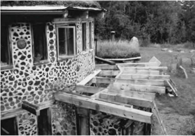
The completed floor framework is shown in Fig. 5.19.


Leave a reply