FUEL CONSUMPTION

The European Asphalt Pavements Association and Eurobitume report of 2004 entitled Environmental Impacts and Fuel Efficiency of Road Pavements (Beuving et al., 2004) is one of the main sources forming the basis for this section of the present chapter.

Rolling resistance is one of the numerous factors of intense interest when con­sidering the problem of fuel consumption while driving, especially in the context of SMA. Rolling resistance may be defined as the force necessary to move a vehicle along a pavement.

At a constant speed of 80 km/h, approximately 12% of the energy loss (fuel consumption) of a heavy truck is consumed in overcoming the roll­ing resistance; the energy spent on overcoming this resistance equals about 30% of the potential available mechanical power at the engine crankshaft (Sandberg, 2001).

Briefly, the rolling resistance is affected by microtexture, macrotexture, megatex­ture, and the unevenness of a wearing course.

According to Dutch research (Roovers et al, 2005), rolling resistance can be ranked by type of wearing course (results in cR[%]) as follows:

Cement concrete with burlap (smooth)—0.86 SMA 0/8—0.86

Double layer porous asphalt 2/6—0.97

Double layer porous asphalt 4/8—1.02

Cement concrete transversely brushed (rough)—1.04

Single layer porous asphalt 6/16—1.05

Dense AC 0/16—1.09

Mastic asphalt 0/11—1.18

Finally one should remember that rolling resistance measurements are strongly influenced by weather (e. g. sidewind velocity). Weather conditions could affect the test results.

Swedish investigations (Sandberg, 2001) have additionally pointed out that the pavement unevenness increases fuel consumption by as much as 12%, which seems to be a more significant factor than the type of asphalt surfacing.

TYPES OF PAINT

Years ago, painters who worked with oil-based paints, lacquers, and varnishes in poorly ventilated spaces didn’t last long in the trade. A serious whiff of the solvents in those products would spin your brain and stagger your feet. Fortunately, most of the paint sold in this country today is water based, which is a lot less hazardous to use and cleans up with soapy water. The best latex paint contains a large amount of acrylic resin. Vinyl acrylic is the second-best choice. Vinyl resin is the least durable option.

Oil-based paints are still around but are mainly used by profes­sional painters. Even among pros, alkyd paints containing synthetic resins have largely replaced oil-based paints. Alkyds are great when you want a glossy surface, but they are harder to apply than latex paints, take longer to dry, and are more work to clean up (requiring paint thinner).

Usually, there are three grades of paint: Good-quality paint has a 10-year warranty, better-quality paint offers 15 years, and best-quality paint offers 20 years. Flat-finish paint has more pig­ment than gloss paint, so it covers better than gloss but also wears faster. That said, when evaluating two similar products (different brands of flat-finish latex paint, for example), a higher content of solids indicates a better-quality product. However, don’t compare across categories, such as flat to gloss.

One problem with paint is that it contains solvents, which release volatile organic compounds (VOCs) into the air as they evaporate. These compounds can make some people sick. Latex paints contain far lower levels of solvents than alkyds, but they can still be bothersome to some people. If fumes are a problem for you, choose one of the low-VOC paints on the market (see Resources on p. 279).To minimize indoor fumes, keep the windows open and run a good fan to promote ventilation.

or the other or right in the center, as necessary. At this point, some folks like to apply another coat to give a texture to the walls before paint­ing. Texturing is common in the west and southwest. It is usually done by blowing a thin mixture of drywall mud onto the walls using an air compressor.

Подпись: Plastic wrap makes good short-term storage for brushes and rollers. When you stop painting to have lunch or simply take a break, there's no need to clean your brush or roller. Instead, just wrap it in plastic until you get back to work.

STEP 6 PAINT THE CEILINGS AND WALLS

Our prairie home seldom, if ever, had any paint on the exterior. The siding became as grained and leathery as the faces of the inhabitants. Indoors, we sometimes used a dry powder, called Kalsomine, that we mixed with wa­ter and used to paint the ceilings and walls. Kalsomine came in different colors, which added a bit to our rooms and to our lives.

After I left home, it seemed that the only interior paint color in existence was Navajo White. For years, the interior of every house we built was painted this off-white color. It was a breath of fresh air to see all the bright colors that exploded in the late 1960s and early 1970s. From bland to bright to subtle pastels and now back to Navajo White—so much for progress.

Paint prep is the key to a good paint job

Professional painters know from experience that the biggest part of a paint job is the preparation. You don’t just grab a bucket of paint and a roller and have at it. Take time to remove doors from their jambs before you start painting the walls and ceilings. Number or label the doors so you’ll know later where each one belongs.

Some drywall jobs create lots of dust that must be removed before you can paint. I use a vacuum cleaner to remove dust from the walls and ceilings, but a broom or a pole sander wrapped with a cotton cloth also works well. Take it easy, because topping compound is relatively soft and easily scratched. Pay special attention to dust in the corners. Remove any drywall mud or dust left in electrical outlets, and scrape up any globs of drywall compound

Lead Framers (continued)

Ability to Impart Knowledge to Other Framers

• When teaching someone, start with the basics. Assume nothing. Explain in clear and simple language exactly what the job is, and how it is to be done.

• The easiest way to lead may be to give orders, make demands, and threaten. However, it creates an unsettling atmosphere that is not conducive to a cooperative, self-motivated crew. Request that framers do tasks; do not order them.

• Assume that no framer intentionally does something wrong. Help your crew correct errors and show them how to avoid making them again.

• Treat each framer with respect. His time may be less valuable to the company, but his worth as an individual is equal to yours.

• The words “please" and “thank you" can make a framer feel much better about working for you. It is an easy way to let him know that what he does is important and appreciated.

• Do not give the hard, unpleasant jobs to the same framer time after time. The entire crew should share such tasks.

• When a framer asks you a question, give him the answer, but then explain how you got the answer so the next time he can figure it out himself.

Ability to Motivate Other Framers

To produce good work efficiently, a framer must be motivated. To be motivated, a framer must:

• Feel good about himself

• Feel what he is doing is important

• Be respected by his lead framer

• Feel he is being treated equally

Feel good about himself

You are a lead framer, not a therapist, but your attitude toward your crew should have a positive effect on his motivation. A crew whose members take pride in their individual and collective skills will invariably produce quality work and take pleasure in doing it.

Feel what he is doing is important

Every task, no matter how small, is necessary to complete the job and, therefore, important.

Be respected by his lead framer

Take time to listen and teach. If, as lead framer, you are called upon to solve a framing problem, it is better to let the framer explain his solution first and, if it is an acceptable solution, let him do it his way. There are often several ways to solve a framing problem. If you have a way that is much faster or easier than the framer’s way, explain it to him and tell him how you came to your conclusion.

Directions should be given in terms of the job, not the individual. For example: Negative—“I told you five minutes ago to build that wall." Positive—“We need that wall built right away so we can finish this unit."

Framers like to feel that the person supervising is concerned about what they think and how they feel. Convey this through your words and actions.

Feel he is being treated equally

Don’t show favoritism when assigning tasks. Make every effort to treat all framers fairly. Deal with any complaints impartially.

EARTH RETAINING WALL CLASSIFICATION

A classification system is an essential part of the description and selection of different earth retaining wall types. Figure 8.1 indicates the many types of walls that are possible.

Earth pressure walls can be classified logically into three categories according to their basic mechanisms of retention, or into three categories based on their source of support. The retention mechanisms include internally stabilized, externally stabilized, and hybrid systems. The sources of support are described as gravity, semigravity, and nongravity.

An externally stabilized system uses a physical structure to hold the retained soil. The stabilizing forces of this system are mobilized either through the weight of a mor – phostable structure or through the restraints provided by the embedment of the wall into the soil, if needed, plus the tieback forces of anchorages.

An internally stabilized system involves reinforced soils to retain fills and sustain loads, adding reinforcement either to the selected fills as earth walls or to the Retained Earth directly to form a more coherent stable slope. These reinforcements can either be layered reinforcements installed during the bottom-to-top construction of selected backfill material, or be driven piles or drilled caissons built into the retained soil. All this reinforcement must be oriented properly and must extend beyond the potential failure plane of the earth mass.

A hybrid or mixed system is one that combines elements of both externally and internally stabilized systems.

Regarding sources of support, gravity walls derive their capacity through the dead weight of the wall itself or through an integrated mass that can be either externally or internally stabilized. They can further be classified into four types. The first is an inter­nally stabilized system: earth walls with either facing covered cuts in situ doweled with uniformly spaced top-to-bottom constructed nails or selected fills reinforced with tensile reinforcements, which can be either metal (inextensible) reinforcements or geotextile (extensible) reinforcements. The second type is an externally stabilized system, either modular precast concrete walls or prefabricated metal bin walls. Third is an externally stabilized system—generic walls such as masonry, stone, dumped-rock, and gabion walls. The fourth type is an externally stabilized cast-in-place mass concrete wall or low-cost cement-treated soil wall system with anchored precast concrete facings.

Semigravity walls derive their capacity through the combination of dead weight and structural resistance. Semigravity walls designed with different shapes can be further classified into two groups: first is the conventional cast-in-place cantilever concrete wall, and second is a prefabricated system wall with cast-in-place base and many

kinds of innovative precast or posttensioned stems. Semigravity walls are, in general, externally stabilized systems. They can be constructed either on spread footings or on deep foundations, such as caissons or piles, as foundation conditions may demand.

Nongravity walls derive their capacity through lateral resistance, either by embed­ment of vertical wall elements into firm ground, by anchorages provided by tiebacks, by dowel actions provided by piles, or by caissons drilled into a stabilized zone. They can be classified into, first, an externally stabilized system with embedded cantilever wall elements, sheet piles, drilled shafts, or slurries; second, similar embedded walls utilizing multiple anchorage tieback systems; and third, internally stabilized systems such as creeping slopes externally covered with multianchored facings and internally doweled with pile or caisson inclusions.

Wall selection is an iterative process that involves cycles of preliminary design and cost estimation. The first and most important step is to define the design problem with design objectives and constraints. The objective of almost all design problems is least cost, although there will be many cases, particularly in urban areas, where objectives will include aesthetic and environmental considerations as well. Costs such as those for materials and construction are much easier to quantify than are aesthetic and envi­ronmental costs. In the latter instances, it is sometimes difficult to verify which one of the feasible solutions is the best. In order to find solutions that are at least feasible, constraints such as serviceability requirements (wall horizontal movement, vertical differential settlement, etc.) and spatial limitations (rights-of-way, underground ease­ments, etc.) should be defined as comprehensively as possible. Designs (wall types) that meet the prescribed constraints are all feasible solutions. A ranking of these feasible solutions (wall types) is required. The ranking should include spatial behavior and economic factors as discussed later in this article. Ideally, the wall with the highest rank should be adopted for detailed design; the rest can be used as design alternatives or discarded if the selected wall is confidently lowest cost, or is the only wall that satisfies all the established design requirements.

At the beginning of the selection process, rough sketches labeled with wall types should be adequate to screen out unfeasible types. As the selection process proceeds, a conceptual design with preliminary dimensions should be generated. Factors affecting the selection of an earth retaining structure may be grouped into three categories: spatial constraints; behavioral constraints; and environmental, aesthetic, and economic con­siderations. Factors to be considered for each of these categories are listed below.

1. Spatial constraints

A. Functions of wall

(1) Provide room for roadway at front of wall

(2) Retain roadway at back or top of wall

(3) Provide for grade separation, landscaping, or noise control

(4) Provide for ramp or underpass wall support

(5) Provide for temporary shoring of an excavation

(6) Ensure stability of steep side slope

(7) Flood control

(8) Serve as bridge abutment

(9) Other

B. Space limitations and site accessibility

(1) Right-of-way boundaries

(2) Geological boundaries

(3) Access of material and equipment

(4) Temporary storage of material and equipment

(5) Maintaining existing traffic lanes or widening

(6) Temporary and permanent easement

(7) Other

C. Proposed finished profile (using combinations of different wall types along the wall alignment may be the optimal solution)

(1) Limit of radius of wall horizontal alignment

(2) Cut or fill with respect to original slope

(3) Minimal site disturbance:

(a) Anchored wall with minimal cut

(b) Stepped-back wall on terrace profile

(c) Superimposed or stacked low walls

(d) Mechanically stabilized earth (MSE) wall with truncated base or trapezoidal reinforced zone

D. Check available space versus required dimensions

(1) Working space in front of wall (shoring, formwork, etc.)

(2) Wall base dimension

(3) Wall embedment depth

(4) Excavation behind wall

(5) Underground easement

(6) Wall front face battering

(7) Superimposed walls or trapezoidal profile of wall back

2. Behavioral constraints

A. Earth pressure estimation (magnitude and location)

(1) The magnitude of the earth pressure exerted on a wall is dependent on the amount of movement that the wall undergoes.

(2) The vertical component of earth pressure is a function of the coefficient of friction and/or relative displacement (settling) between wall (stem, facing, and Reinforced Earth mass) and retained fill.

(3) Compaction of confined soil may result in developing of earth pressure greater than active or at-rest condition.

(4) For complex or compound walls such as bridge abutments, battered-faced walls, superimposed walls, and walls with trapezoidal backs, a global limit equilibrium analysis is required.

(5) For embedded cantilever walls, profiles of lateral pressures acting on both sides of a wall are affected by the location of the center of wall rotation (pivot point), which is construction-dependent.

(6) For multianchored embedded cantilever walls using a minimum penetra­tion depth where there is no static pivot point, the soil pressure profile is anchorage design-dependent and should be developed with the recognition of beam-on-elastic foundation principles.

(7) At the ultimate limit state, the location of the horizontal earth pressure resultant moves up from 0.33 to 0.40 of the wall height.

B. Groundwater table

(1) Reduce hydrostatic pressure if possible by an appropriate drainage system.

(2) Introduce special precautions to reduce corrosion.

(3) Prevent soil saturation; an appropriate groundwater drainage system is required except when the water table level must be maintained to prevent settlement of adjacent structures.

C. Foundation pressure estimation

(1) Uniform average pressure by Meyerhof effective width method for mechanically stabilized earth wall systems

(2) Maximum toe pressure by flexural formula method for unreinforced or reinforced concrete-type walls

D. Allowable bearing capacity estimation

(1) Allowable bearing capacity is limited by and related to preset settlement or differential settlement criteria.

(2) Earth walls integrated with wider flexible bases are allowed higher bearing capacity and tolerate more settlement than rigid walls on spread footings.

E. Allowable differential settlement

(1) Settlement is a time-dependent behavior.

(2) Top-of-wall settlement is a sum of settlement from wall and from subsoil strata.

(3) Allowable settlement should be evaluated by considering tolerable move­ment of superstructure and wall precast facings.

(4) Simple-span bridges tolerate more angular distortion between adjacent footings than continuous-span bridges.

(5) Tolerable (vertical and horizontal) movement of a wall facing is a function of panel joint width and pattern of connection.

F. Earth pressure on wall facing

(1) The rigidity and slope of a wall facing affect the development of lateral pressure and displacement at facing.

(2) The earth pressure is reduced with a decrease in facing stiffness, while the facing deformation is only slightly increased for a decrease in stiffness.

G. Settlement and bearing capacity improvement techniques

(1) Surcharge (two-phase construction) to hasten anticipated settlement

(2) Drainage (wick drain) to hasten anticipated settlement in fine-grain silt and clay substructure materials

(3) Excavation and compaction of a portion of weak foundation material

(4) Addition of reinforcement to subsoil

(5) Use of lightweight fill material to minimize loads beyond existing precom­pression of foundation materials

H. Methods of reducing settlement on reinforced mass

(1) Increasing compaction of fill material

(2) Using more reinforcements (length, area, and spacings of reinforcements)

(3) Cement treatment of fills

(4) Reducing clay content of fill

(5) Using high-density in situ micronails

I. Earth pressure applied at facing

(1) High: facing with posttensioned anchors

(2) Medium-high: mechanically stabilized earth wall with full-height panels

(3) Medium: rigid concrete facing with inextensible reinforcements

(4) Medium-low: concrete panel facing with extensible reinforcements

(5) Low: concrete panel facing with nailed soil

J. Wall base width

(1) Wall types, foundation types

(2) Allowable bearing capacity of spread footing

(3) No tension allowed at heel of spread footing

(4) Internal and external stability of wall

(5) Reinforcement length to control lateral movement of Reinforced Earth wall

(6) Hybrid walls to reduce wall base width

K. Toe penetration depth of embedded cantilever wall

(1) Water cutoff consideration

(2) Heave in front of wall

(3) Bearing capacity

(4) Stability of passive toe kickout

(5) Slope of ground in front of wall

L. Wall sensitivity to differential settlement

(1) High: cast-in-place concrete retaining walls

(2) Medium: earth walls with inextensible reinforcements, geogrid walls with facings, precast modular walls

(3) Medium-low: geofabric walls without facing

(4) Low: gabion walls, crib walls, embedded cantilever walls, multianchored cantilever walls

M. Potential settlement of retained mass

(1) High: embedded cantilever walls

(2) High-medium: some concrete modular walls, geofabric walls

(3) Medium: cast-in-place concrete retaining wall, concrete modular walls, geogrid walls

(4) Medium-low: earth walls with inextensible reinforcements

(5) Low: multianchored embedded cantilever walls

N. Relative construction time

(1) Long: cast-in-place concrete walls

(2) Medium: earth walls with reinforcements

(3) Short: embedded cantilever walls, multianchored embedded cantilever walls, precast modular walls

O. Wall design life

(1) Structural integrity

(2) Color and appearance

P. Load-carrying capacity and settlement of deep foundation

(1) Maximum frictional resistance along the pile shaft will be fully mobilized when the relative displacement between the soil and the pile is about *4 in irrespective of pile size and length.

(2) Maximum point resistance will not be mobilized until the pile tip has gone through a movement of 10 to 25 percent of the pile width (or diameter). The lower limit applies to driven piles, and the upper limit is for bored piles.

(3) The ultimate load-carrying capacity is the sum of pile point and total fric­tional resistance.

(4) Pile-to-cap compatibility should be considered, especially with battered piles and semirigid pile-cap connection.

(5) For the estimation of group efficiency in vertical and horizontal displace­ment, calculation of pile group, pile diameter, spacing, soil type, and total number of piles should be considered.

Q. Fill material properties

(1) The lower the soil friction angle, the higher the internal earth pressure restrained by the wall.

(2) The lower the soil friction angle, the lower the apparent friction coeffi­cient for frictional reinforcing systems.

(3) The higher the plasticity of the backfill, the greater the possibility of creep deformation, especially when the backfill is wet.

(4) The greater the percentage of fines in the backfill, the poorer the drainage and more severe the potential problem from high water pressure.

(5) The more fine-grained and plastic the fill, the more potential there is for corrosion of metallic reinforcement.

R. Fill retention versus cut retention

(1) Fill retention (bottom-to-top construction)

(a) Earth walls (extensible and inextensible tensile reinforcements)

(b) All semigravity walls

(c) Modular walls, generic walls, and mass concrete walls

(2) Cut retention (top-to-bottom construction)

(a) Earth walls, soil nails

(b) All nongravity walls

3. Environmental, aesthetic, and economic considerations

A. Environmental constraints

(1) Ecological impacts on wetlands

(2) Effect of corrosive environment on structural durability

(3) Water pollution, sediment, or contaminated material

(4) Noise or vibration control policy

(5) Stream encroachment

(6) Fish and wildlife habitat or migration routes

(7) Unstable slope

(8) Other

B. Aesthetic constraints

(1) Urban versus rural

(2) Design policy of scenic routes

(3) Acoustic or aesthetic properties of wall facing

(4) Antigraffiti wall facing

(5) Avoiding valley effect of long or high wall

(6) Other

C. Economic considerations

(1) Construction schedule

(2) Availability of fill material

(3) Supply of laborers

(4) Heavy equipment requirements

(5) Formwork, temporary shoring

(6) Dewatering requirements

(7) Available standard designs

(8) Temporary versus permanent wall and future widening

(9) Cost of drainage system

(10) Design and installation of wall attachments

(11) Negotiated bidding and design/build on nonstandard projects

(12) Maintenance cost, readjustment, and remodeling

(13) Uncertainty of site and wall loads

(14) Complexity of project

(15) Height differences in finished or base grades

(16) Number of wall turning points

(17) Scale of project

(18) Length or height of wall—quality control of fill material

(19) Posttensioning, grouting, trenching, slurry

(20) Pile driving, caisson drilling

(21) Precasting, transportation, and inspection

(22) Quantity of excavation

(23) Quantity of backfill material

(24) Experience and equipment of local contractor

(25) Proprietary product and quality assurance

(26) Other

The logical consequence of considering these factors is to reduce the number of fea­sible wall types. The first stage of the decision process eliminates obviously inappropriate walls through spatial and behavior constraints before considering economic factors. The behavior constraints involve the properties of the earth the wall must retain and the ground it rests on. A detailed geological investigation and soil property report is needed in the second stage of the decision process. At this stage, conceptual designs with dimensioned wall sections and subsoil strata are required. In the third stage, behavior constraints and economic constraints should be repeatedly or simultaneously considered.

After identification of the feasible set of wall types (a subset of the available walls), work proceeds on the more refined or detailed preliminary designs. Then a rating of these feasible designs should be made.

To consider the various factors during the selection process, use the worksheets shown in Figs. 8.2, 8.3, and 8.4, along with the properly defined design problems (objectives and constraints) and cost requirements (Fig. 8.5). These sheets form a part of the documentation in support of the final selection(s).

After the worksheets are completed, a list of selected wall types with conceptual designs should be generated. A rating matrix can then be developed for a qualitative eval­uation of the selected alternatives. On the basis of each evaluation factor, a qualitative rating between 1 and 5 can be given each alternative. The qualitative ratings are usually multiplied by weight factors reflecting the importance of the factors; usually, cost – and durability-related factors are given higher weights than the rest. The alternative(s) with the highest score is (are) then selected for final design and detailed cost estimation.

The intent of this procedure is to identify equally satisfactory alternative wall types. The plans or specifications will provide the opportunity for the contractor to select from the acceptable alternatives, should the designer make the decision to permit alternative walls. The specifications will outline the acceptable alternatives with dimensioned conceptual designs and indicate the requirements for the contractor to submit final site-specific details. These submitted (design/build) shop drawings should clearly establish that the design criteria are satisfied. They may include aesthetic features, bearing capacity and stability requirements, design computations for the alternative site-specific selection signed and sealed by a licensed professional engineer, and other data as may be necessary to document compliance with project needs.

PIPE CAPACITIES

Have you ever wondered what the capacity of a pipe was? You could do some heavy math to figure out the answer to your question, or you can look at Fig­ure 11.16 for quick solutions to your questions.

WHAT IS THE DISCHARGE OF A GIVEN PIPE SIZE UNDER PRESSURE?

What is the discharge of a given pipe size under pressure? The pressure and flow are both factors to consider. If you assume that you are dealing with a straight pipe that has no bends or valves, I can give you a reference chart to use for answers to your question. Further assume that there will be open flow, with no backpressure, through a pipe with a smoothness rating of C = 100. Refer to Figures 11.17, 11.18, and 11.19 for quick-reference charts.

PIPE CAPACITIES

FIGURE 11.17 ■ Discharge of pipes in gallons per minute.

PIPE CAPACITIES

FIGURE 11.18 ■ Discharge of pipes in gallons per minute

Conditional probability approach

This approach starts with a selection of key components and modes of opera­tion whose states (operational or failure) would decompose the entire system into simple series and/or parallel subsystems for which the reliability or failure probability can be evaluated easily. Then the reliability of the entire system is obtained by combining those of the subsystems using the conditional probability rule as

ps, sys — ps | Fm x ps, m + ps | Fm x pf, m (T.65)

in which ps | and ps | Fm are the conditional system reliabilities given that the

mth component is operational Fm and failed Fm, respectively, and ps, m and pf, m are the reliability and failure probabilities of the mth component, respectively.

Except for very simple and small systems, a nested conditional probability operation is inevitable. Efficient evaluation of system reliability of a complex system hinges entirely on a proper selection of key components, which generally is a difficult task when the scale of the system is large. Furthermore, the method cannot be adapted easily to computerization for problem solving.

Example 7.15 Find the system reliability of the water distribution network in Fig. 7.9 using the conditional probability approach.

Solution Using the conditional probability approach for system reliability evaluation, first select pipe section 1 as the key element that decomposes the system into a simpler
configuration, as shown in Fig. 7.13. After the entire system is decomposed into a simple system configuration, the conditional probability of the decomposed systems can be evaluated easily. For example, the conditional system reliability, after imposing F1 and F3 for pipes 1 and 3, respectively, can be expressed as

Ps, sys | F[,F3 = P(F2 n F4n F5) = (0.95)3 = 0.8574

where ps | f ‘,f3 is conditional system reliability. Conditional system reliabilities for other imposed conditions are shown in Fig. 7.13. After the conditional system re­liabilities for the decomposed systems are calculated, the reliability of the entire

Conditional probability approach

Original system

system can be combined using Eq. (7.65). For this particular example, the system reliability is

Ps, sys = Ps | F, F3 x P(F1, F3) + Ps | F, F3,F2 x P(F1, F3, F2)

+ Ps | F1,F,,F2 x P (F1> F3, F2)

= (0.8574)(0.95)(0.05) + (0.9975)(0.95)3 + (0.9025)(0.95)2(0.05)

= 0.9367

Materials

Trim materials include custom-milled hard­woods; softwood boards, molding, and stock caps; MDF (medium-density fiberboard); and polymer moldings that replicate detailed histori­cal styles in lightweight, easy-to-install sections.

CHOOSING TRIM

Because trim is costly (especially hardwood trim), buy it from a local shop that mills its own. That way, you’ll be more likely to get trim that is straight, knot-free, and stored in humidity – and temperature-controlled warehouses. If you’re trying to match existing trim, a local milling shop is also your best bet. You may pay a setup fee but, all in all, the final cost of a room or two of custom trim may be more reasonable than you think.

Stock trim from a lumberyard or home center is often so warped that you must pick through the racks and eyeball each piece to see if it’s straight. Discard any pieces that are obviously heavier than the rest—usually a sign of excessive moisture. (Trim is typically dried to 7 percent to 10 percent moisture content.) Examine each piece for splits and cupping across the width.

Also sight down the length of each board for excessive twisting. You can force a twisted piece into position by toenailing and clamping it, but the extra stress is likely to open a joint or cause splitting down the road.

If you want the wood grain to show, be even more picky or pay more for a select grade. But if you plan to paint the trim, most surface blemishes can be sanded, filled, or sealed with white pig­mented shellac (see Chapter 18) or a primer-sealer to suppress knot or tannin bleed-through. Finger – jointed molding, which joins short sections of clear softwood, is another option. Though usually painted to conceal its glued finger joints, finger- jointed molding is also available with a wood veneer, which can be stained and clear finished.

COMBINING STOCK ELEMENTS

Standard molding is often milled from 1-in. stock (actual size, % in.). Thus you’ll find it easy to create more complex trim by combining 1-in. boards with stock molding caps. For example, with baseboards, you might start with a 1×8, add a quarter-round shoe at the bottom and a cove- molding cap at the top.

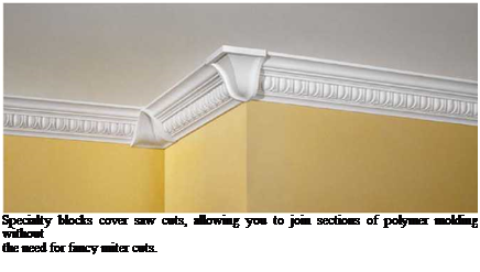
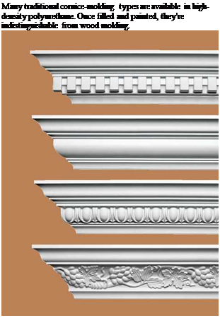
However, if you want to dress up a room with complex crown moldings, consider installing polymer millwork instead—whose monolithic casting greatly simplifies installation. Likewise, though you can build them up by hand, mantels and fireplace surrounds also are sold as pre-

Подпись: Specialty blocks cover saw cuts, allowing you to join sections of polymer molding without the need for fancy miter cuts. Most glues will bond MDF, but PRO-TIP

Don’t bring trim stock to a job site till the drywall joints are dry and the building is heated. Otherwise, trim ends will absorb moisture, swell, and become dif­ficult to install. Never store trim in unheated areas or garages.

1111

^^PROnP

Подпись: its edges tend to suck water out of the thinner ones. To minimize this tendency, double-glue joints (rub in a thin first layer to seal the edges, then a second to bond the joints) or apply glue size to seal the edges. Polyurethane glue is probably the best allaround choice.Подпись: llllПодпись: Many traditional cornice-molding types are available in high-density polyurethane. Once filled and painted, they're indistinguishable from wood molding.

assembled units and as kits requiring minimal assembly.

You can combine stock moldings with rela­tively inexpensive paneling to make wainscoting and frame-over-panel walls. By cutting a piece of paneling in half, you can use two sections, each 4 ft. by 4 ft., topped with a built-up combination of moldings to form a cap. Paneling with vertical, regularly spaced grooves gives the illusion of individual boards. To change the style and create Craftsman-style wainscoting, you could use!4-in.- thick redwood plywood with the grain running vertically and install redwood strips every foot or two to create detail and cover the seams between sheets. For more, see “Wainscoting,” on p. 430.

Apply the second and third coats

Drvwall compound must be applied in several thin coats because thick applications tend to shrink and crack. Also, thin coats can be feathered or tapered very gradually so that they’re invisible (or nearly so) after the dry – wall surface is painted. Before applying the second coat, remove any lumps, high spots, or ridges of hardened compound left from the first coat. This can be done with a drywall knife or a pole sander. Be careful not to over­sand, or you could damage the paper face of the drywalk

Apply topping compound over the dimples around the fasteners, just as you did with the first coat. Be even more careful as you level the compound, and use a 10-in. or 12-in. knife. Along seams, apply topping compound with a 5-in. knife, then use a 12-in. knife to remove the excess (see the photo at right). Again, take your time. The second coat should conceal the tape. Using a wider knife, feather the mud away from the center of the joints to make them harder to detect. This is espe­cially important at butt joints. It takes some practice to get this coat right. Go over the joints more than once, if necessary, pulling the knife with a steady, even pressure to leave a smooth surface.

The same can be done along inside corners, using a 5-in. knife to mud and smooth one side of the corner at a time. This takes some skill, because it’s difficult to keep the knife from marking the finished side as you mud the opposite side. For this reason, some tapers like to use a different procedure. They apply mud on one edge at a time, smooth it, and then let it dry. Once one side of the corner is dry, they return and do the other side.

Before applying the third coat of com­pound, lightly sand the second coat. Hit the corners, dimples, and seams with a 120-grit
screen on a sanding pole to remove any bumps, trowel marks, or ridges. The third coat should be little more than a light application of topping compound to hide any imperfec­tions and feather the seams a bit wider. To make the topping compound easier to manip­ulate, thin it with a little water.

Sand drywall compound

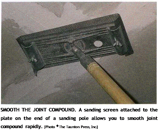
Some tapers are so good that almost no sand­ing is required to make their drywall applica­tions look nearly perfect. When I drywall, I can expect to spend some time with the sand­ing pole (see the photo on p. 232). Before you get started, make sure you have a good dust mask that seals well, because sanding drywall produces a lot of fine dust that can irritate your eyes and lungs. Goggles will help keep the dust out of your eyes. Use a 120-grit screen on the block at the end of the pole sander, and push the sander gently along the

Подпись:Подпись: І іПодпись: Helping HandПодпись: Clean up as you go. When left lying around, scrap pieces of drywall crumble easily, making a paper and powder mess that can be tracked all over a job site. Avoid this by cleaning up drywall as you go. Stack usable pieces so they are easily accessible.seams and corners with steady, even pressure. The key word for beginners is “gently.” Its easy to get carried away, sanding through the mud and exposing the tape or damaging the dry – walPs paper face. If you do, apply another coat of compound to those areas and sand again after the compound has dried.

A final, light sanding can be done with a 150-grit screen, some hand-held sandpaper, or even a damp sponge. Sandpaper folded into a “V” allows you to smooth out imperfections in inside corners by putting pressure on one side or the other or right in the center, as nec­essary. At this point, some folks like to apply another coat to give a texture to the walls before painting.

STEP 6 Paint the Ceilings and Walls

Our prairie home seldom, if ever, had any paint on the exterior. The siding became as grained and leathery as the faces of the inhab­itants. Indoors, we sometimes used a dry pow­der, called Kalsomine, that we mixed with water and used to paint the ceilings and walls. Kalsomine came in different colors, which added a bit to our rooms and to our lives.

After I left home, it seemed that the only interior paint color in existence was Navajo White. For years, the interior of every house we built was painted this off-white color.

It was a breath of fresh air to see all the bright colors that exploded in the late ’60s and early 70s. From bland to bright to subtle pastels and now back to Navajo White— so much for progress.

NAILING AND DRILLING

Because most trim is light, it is usually nailed up with finish nails, which have slimmer shanks and smaller heads than other nails. Trim-head screws (shown in the photo on p. 90) are often specified when molding is heavy or complex or when trim pieces will be subject to twisting or flexing, as happens with door frames and stair treads.

A finish hammer has a smaller head than a framing hammer and so is easier to control when trying to avoid denting the trim. Stop when the nail head is almost flush with the wood surface; then use a nail set to drive the nail head below the surface. Always set nails before sanding or finishing.

Finish nailers have largely replaced hand nail­ing, because pressure settings can be adjusted so the nail goes just below the surface; thus you don’t have to set the nails. Finish nailers won’t dent trim, and you can nail with one hand while holding joints together with the other. Production carpenters favor pneumatic models with air hoses running to a compressor, but cordless models with spare batteries work well, too, for installing small amounts of trim.

Nailers are designed to shoot specific nail gauges (thicknesses). Standard finish nailers

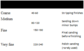
Подпись: True Grit: Which Sandpaper for WhatПодпись: COMMON NAME GRIT NUMBER ("teeth"/sq. in.) USES Coarse 40-60 Stripping finishes Medium 80-120 Sanding down minor bumps Fine 150-180 Final sanding before finishing Very fine 220-240 Polish sanding (rarely used) Подпись: A SANDPAPER Pimage839

shoot 15-gauge nails, whereas brad nailers (pin tackers) shoot 18-gauge to 20-gauge brads. (The higher the gauge number, the thinner the nail shank and the weaker the nail.) Most home­owners should stick with 15-gauge nailers, but brad nailers are great for tacking up trim: Brad holes are tiny, so you can easily pry off and repo­sition the trim if needed. Brads are also useful for attaching thin cabinet elements like finish toekicks or cabinet side panels. If you don’t have many brads to drive, use a hand brad pusher.

Cordless drill drivers are the essential tool in most carpenters’ belts. Although they range up to h-in., 18-volt monsters, unless you’ve got fore­arms like Popeye get a 18-in., 12-volt cordless drill-driver, which has a keyless chuck for quick changing of bits. A 12-volt model accepts either drill bits or screw tips and has plenty of power for finish carpentry tasks. For production carpen­ters, the next step up in power (and price) is a 12-volt impact driver, which accepts only screw tips; some models can drive more than 250 two – inch screws on a single battery charge. (Whichever tool you buy, get a spare battery for recharging while you work with the other one.) You’ll find more on drills, drivers, and bits in Chapter 3.

image840

When it comes to finish nails and nailers, smaller is often better. This pin nailer weighs less than 5 lb. and shoots 1-in. to 272-in. nails.

Sandpaper is coated with tiny abrasive particles (grit), which make tiny cuts in the material being sanded. Sandpaper is rated according to the concentration of grit per square inch.

The lower the grit number, the larger, coarser, and more widely spaced the grit particles. Conversely, the higher the grit number, the finer and more closely spaced the grit is.

The abrasive on today’s sandpaper will be either aluminum oxide, silicone carbide, ceram­ic particles, or garnet. Aluminum oxide is the most common abrasive for sanding wood because it’s relatively long lasting; whereas sil­icone carbide, being harder, is better for sand­ing metal, fiberglass, paint, and such. If you’re renting a big drum sander to strip wood floors, its belts will likely be low-grit ceramic sand­paper. Garnet, the softest of the bunch, is often the grit found on fine and very fine sandpapers.

If you’re sanding wood, avoid closed-coat sandpaper, which will clog quickly because there’s no place for wood dust to go. A better choice for woodworkers is open-coat sandpaper, in which only one-third to two-thirds of the surface is coated with grit. Closed-coat sand­paper is used to sand metal.

Managing Your Team

Construction is a unique industry. It is always changing. Each new job or building has its own individual plan, timetable, and workers to do the job. The economy, local governments, codes, tools, and materials are also constantly changing, creating different work environments. The crew structure has to change, as necessary, to accommodate the particular requirements of a job. To be efficient, the lead framer must be aware of all factors that affect the job, and must be able to work successfully within them.

The management structure of a framing crew can differ from company to company. In some cases, the lead framer is the owner/builder. In larger construction companies, the lead framer may run only the framing crew. Either way, the lead framer leads the framing on the job.

This book is not intended to cover the functions of the framing contractor or builder that include office management, bids, payroll, or business organization. It is written for someone who already has experience, knowledge, and skills in basic framing, and who wants to move up to the next level or become a better lead framer.

As a lead framer, you need to have a different perspective from a crew member. When you are working on your own, the amount of work completed depends on you. When you are leading a crew, the amount of work finished depends on the whole crew. On your own, you have complete control over what can be done, whereas you have limited control over how much work your crew gets done. Nevertheless, you only need a little control and increased knowledge to make a big difference in how much work the crew finishes. This chapter is intended to give you that increase in knowledge— which can make your jobs run better.

The Role of Lead Framers

A Lead Framer Must Possess:

1. Knowledge to frame any building

2. Ability to impart knowledge to other framers

3. Ability to motivate other framers

Knowledge to Frame Any Building

As a lead framer, you must thoroughly understand the basic concepts involved in framing any style

building. The framing crew takes their direction from you; you, in turn, take your direction, depending on the situation, from any of the following:

a. Framing contractor

b. Site superintendent

c. Architect or engineer (plans)

d. Owner

There are a number of framing requirements that are easy to overlook. Compile checklists such as the ones shown and refer to them during each phase of the job.

Responsibilities of Lead Framer

□ Check location and quality of power supply.

□ Check location and date of lumber drop.

□ Check window delivery schedule.

□ Check truss delivery schedule when appropriate.

□ Arrange to have the builder complete as much site preparation as possible before starting, including leveling the area around the building where framers will be working.

□ Highlight items on plans that are easy to miss or hard to find.

□ Make a list of potential problem areas and items that are easy to forget.