Nail Sheathing

Nail Sheathing

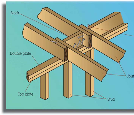
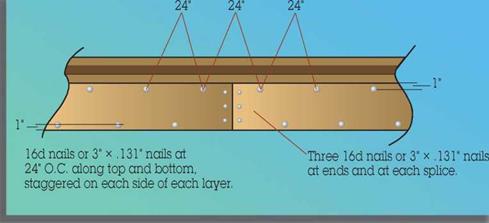
Make sure edges are aligned when nailing girders and beams together.


Nail Sheathing

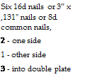
Nail Sheathing Подпись: Six 16d nails or 3” x ,131" nails or 8d common nails, 2 - one side 1 - other side 3 - into double plate

Nail Joist Blocking


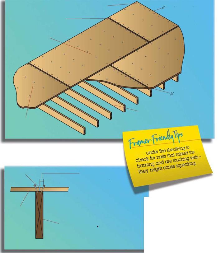
Nail in 1У" from edge


maximum spacing on edges – 9 nails


1/з" space between sheets. (Increase spacing if sheathing is exposed to moisture.)


12" maximum spacing in field – 5 nails


space


Joist rafter or stud


Sheathing


tOO^-


Уз" space


У2" from edge of sheathing to nail (No closer to edge than 3/8".)

  Nail Sheathing

Sheathing


Mark stud/joist/rafter spacing on the sheathing and then align the framing component with the mark before nailing. This ensures straight, evenly spaced framing.


Nail Sheathing

Energy Upgrades Are Cheaper Than You Think

While the cost of fixing wet basements and adding bathrooms can add up quickly, energy upgrades can be folded in without putting projects out of reach. In fact, they don’t really cost that much more because they’re integral to the decisions and choices made in the renovation process.

If you consider your renovation from a whole-house approach, you might find that you can add modern conveniences (an extra bathroom, bedroom, or office space) and comfort without building an addition, and reduce energy costs in the process. The base­ment and attic are already built; you just need to use them. By adding rooms in the basement and attic, you often can reconfig­ure the floor plan to accommodate an extra bathroom, a larger kitchen, or a master suite.

Replacing the furnace, the boiler, or the HVAC system might cost $10,000 before you are done. But the upgrade could easily save $1,000 a year in heating and cooling costs. Even in simple payback terms, this new system would pay for itself after 10 years. Amortized into a 30-year mortgage, it costs $27 per month; the savings works out to $83 per month for a net gain of $56 per month. Because we know energy costs are rising, these numbers will only get better.

Case Studies Illustrate Real-World Challenges

The three homes featured in this chapter have several things in common. First, they are all more than 90 years old. Two of them were built in 1860 and the third in 1916. Second, they all had their major systems totally replaced: new wiring, light fixtures, plumbing, and mechanical systems, includ­ing the addition of central air-conditioning. Third, they all had attic spaces that were incorporated into the living space of the house by moving the insulation from over the second-floor ceiling to under the roof. Fourth, they all had insulation added under

Seven Steps to Net-Zero Energy Use

n renovating old homes into superefficient ones, there is a definite path to success: Start where you can get the most bang, and work your way down the list. After you get past item 5, the house will be efficient enough to downsize the mechanical equipment, which you replaced in step

1. If you’re planning to go at least through step 5, keep that in mind before buying a new boiler or HVAC unit.

1. Upgrade the mechanical systems

An old furnace or boiler is often the worst energy user in an old house. Many houses built prior to 1920 still have old coal-fired boilers that were converted to gas or oil. These units are workhorses, but use a lot of energy. A new furnace or boiler can save energy dollars right away. Replacing window air conditioners, which we did in all these houses, with a central system also can save energy right away, as long as the ductwork has been placed in the conditioned space. Solar water heating is a good option to add here if you can afford it, but at the very least, upgrade the efficiency of hot-water pro­duction by coupling the tank to the boiler.

2. Bring the basement and crawlspace inside the house

Warm, dry basements and crawlspaces can extend living and storage space. Wet base­ments are the source of high humidity levels and discom­fort in the summertime in old houses. They also can be the source of mold growth that gets distributed around the house. Spray foam is a fast, effective way to bring these areas into the conditioned space while sealing the leaks between foundation and floor framing.

3. Superinsulate and air-seal the roof

If air leaks in at the bottom of the house, it leaks out at the top, which makes a house cold and drafty in winter. A poorly insulated roof also can make a house hot in summer. Air­sealing is a by-product of good insulating, so it’s really a one – step process. Using spray foam under a roof also can eliminate the need for roof venting, which is tricky in complicated roofs.

4. Replace the windows

With the bottom and top of the house sealed and insulated,

a new basement slab, as well as insulation applied to the inside of the exterior founda­tion wall. Fifth, they all had at least some windows replaced, and all had new window openings added in critical areas to provide better views of the yard and better daylight­ing to the home. Sixth, all the homes had bathrooms and bedrooms added. Finally, we replaced inefficient window A/C units with central A/C systems in each house.

Because of the work in the basements and attics, all the homes had increased living area without increasing the footprint of the home. And while the living space increased by 30% to 100%, all of them saw a reduction of energy use that ranged from 30% to more than 100%. While the renovations cost more than $100 per sq. ft. for each home, all were appraised at values exceeding that cost after the renovations were complete.

Some things are different in each case, too. The two oldest homes had major structural issues that needed to be repaired before other work could be done. Founda­tions needed to be rebuilt, and additional columns and beams were added for support. One house, the Greek revival, had frequent basement flooding that had to be stopped, and its attached barn was leaning enough to fall down. The Victorian was in a historic

the next opportunity is the walls. Old windows are like big holes in the walls. They often leak both air and water into the house while functioning poorly. They might not open and close properly, and can be obscured with storm windows and screens that diminish the amount of light that can enter. Properly installed, Energy Star (or better) windows seal the holes in the walls to keep out water and weather extremes. (For more, see “A Buyer’s Guide to Windows” on pp. 91-103.)

5. Insulate the walls

Filling empty wall cavities with cellulose is a cheap, easy, ef­fective way to warm up an old house. Blowing cellulose into existing wall cavities is an art, to be sure, but there are many contractors who have been doing it for years. In fact, there are now inexpensive ways to check with infrared cameras to make sure that all voids have been filled without disturbing the existing plaster or sheath­ing on outside walls.

Because siding or shingles on old houses might also have worn out, we take the opportu­nity to install foam sheathing on the outside of the house before re-siding.[1]

6. Buy Energy Star (or better) fixtures, appliances, and lighting

Once you have reduced your space-conditioning and water­heating loads, the lighting, appliance, and plug load will be your next big energy item.

A new Energy Star refrigerator will use 20% less energy than a standard model. Replacing old light fixtures with pin-based

compact-fluorescent fixtures ensures that your electric bill will stay lower (up to 30%).

7. Add a renewable – energy source

Once your energy consump­tion has been reduced signifi­cantly, it becomes reasonable to produce your own energy with systems such as photo – voltaics, wind power, or hydro, if you happen to have a stream nearby.

Until you slash the energy usage, though, it’s not worth the investment in renewable power sources. Conservation is still the cheapest game in town.

district, so even though the chimneys were structurally unsound and the old slate roof was beyond its useful service life, they had to be repaired (at a great cost) rather than replaced.

A focus on durability

Although the details in this book have been selected partly on the basis of their widespread use, the primary focus is on durability. I believe that wood-frame buildings can and should be built to last for 200 years or more. To accomplish this, a building must be built on a solid foundation; it must be designed and built to resist moisture; it must be protected from termites, ants, and other insect pests; it must be structurally stable; and it must be reasonably protected from the ravages of fire. All these criteria may be met with standard construction details if care is taken in both the design and the building process.

There are some accepted construction practices, however, that I do not think meet the test of durability. For example, the practice in some regions of building foundations without rebar is not prudent. The small investment of placing rebar in the foundation to minimize the possibility of differential settlement is one that should be made whether or not it is required by code. The stability of a foundation affects not only the level of the floors but also the integrity of the structure above and the ability of the building to resist moisture. Another common practice that I discourage is the recent overreliance on caulks and sealants for waterproofing. This practice seems counterproductive in the long run because the most sophisticated and scientifically tested sealants are warranted for only 20 to 25 years. Should we be investing time, money, and materials in buildings that could be seriously damaged if someone forgets to recaulk? It is far better, I believe, to design buildings with adequate overhangs or with flashing and drip edges that direct water away from the structural core by means of the natural forces of gravity and surface tension.

Durability, however, does not depend entirely upon material quality and construction detailing. Durability also depends heavily upon the overall design of the building and whether its usefulness

over time is sufficient to resist the wrecking ball. The more intangible design factors such as the quality of the space and the flexibility of the plan are extremely important but are not a part of this book.

on codes

Every effort has been made to ensure that the details included in this book conform to building codes. Codes vary, however, so local codes and building departments should always be consulted to verify compliance.

how the book works

The book’s five chapters follow the approximate order of construction, starting with the foundation and working up to the roof (however, the last chapter on stairs is intentionally out of sequence). Each chapter begins with an introduction that describes general principles. The chapters are divided into subsections, also roughly ordered according to the sequence of construction. Subsections, usually with another more specific introduction and an isometric reference drawing, lead to individual drawings or notes.

Subsections are called out at the top of each page for easy reference. Each drawing has a reference letter, a title, and often a subtitle. Sometimes a reference and title is assigned to an entire topic. With this system, all the drawings (and topics) may be cross-referenced. The callout “see 42A”, for example, refers to drawing A on page 42.

As many details as possible are drawn in the simple section format found on architectural working drawings. Most are drawn at the scale of 1 in. equals 1 ft. or 1У2 in. equals 1 ft., although the scale is not noted on the drawings. This format should allow the details to be transferred to architectural drawings with minor adjustments. (Details will usually have to be adjusted to allow for different size or thickness of material, for roof pitch, or for positional relationships.) Those details that are not easily depicted in a simple section drawing are usually drawn isometrically in order to convey the third dimension.

Any notes included in a detail are intended to describe its most important features. By describing the relationship of one element to another, the notes sometimes go a little further than merely naming an element. Materials symbols are described on page 226. Abbreviations are spelled out on page 227.

WRECKING AND PRYBARS

© Disconnect plumbing pipes and electrical cables in areas about to be demolished—and check with a voltage tester to be sure the power’s off. Be methodical and work slowly.

Подпись: PRO"ГIP When removing casing or molding, use a nail punch to drive finish nails through the back of the trim piece. That's far less damaging than attempting to grip and pull nails from the face side. Подпись: llllWrecking bars have differing lengths and end configurations. Most are crowbars with crooked

Подпись: Wrecking and prybars. 1, Crook-neck wrecking bars; 2, L-bar; 3, flat bar; 4, cat's paw; 5,8-in. prybar/nail puller; 6, cat's paw with punch point. ends for better leverage. The longer the bar, the better the leverage.

L-bars are wrecking bars with a flat L-shaped end instead of a crook. Drive the L into lumber that’s nailed together and twist the tool to pry the pieces apart.

Flat bars (also called Wonderbar® or handy bars) are the best tool to ease off delicate trim without damaging it. Pry the trim up gradually along its length.

A cat’s paw is the tool of choice if you’re pulling a lot of nails out of framing. It bites into wood pretty deeply, so don’t use this tool on trim.

A small cat’s paw with a punch point is small enough to remove finish nails, and its pointed end doubles as a nail punch.

An 8-in. prybar/nail puller lifts trim gently and pulls finish nails.

MISCELLANEOUS TOOLS

Sawhorses support work at a comfortable height. The metal-leg variety, which nail to lengths of 2×4, are sturdy and easy to collapse and store. Black & Decker’s® Workmate® has an integral clamp in its benchtop; it also folds flat for compact storage and transport.

Electrical and plumbing tools are covered in other chapters. But don’t be without a voltage tester (see the bottom photo on p. 235) to make sure the power’s off, slot and Phillips-head screw­drivers with insulated handles, and needle-nose and lineman’s pliers. And every toolbox should have a
pipe cutter, large and small adjustable open-end wrenches (commonly called Crescent® wrenches), slip-nut pliers, and a pair of pipe wrenches.

Earth tools include round-point shovel, pickax, hatchet or ax, and wheelbarrow.

Tools to Rent

Most contractors own the tools listed in this sec­tion, but occasional users should probably just rent them. The decision depends on how often or how long you may need the tools and how pas­sionate you are about collecting them.

SAFETY, SCAFFOLDING, AND JACKS

Inside or out, scaffolding gives you secure footing and peace of mind. Instead of hanging precari­ously from a ladder, you can concentrate on the task at hand. That said, anyone who’s not com­fortable working at heights, shouldn’t. As one contractor put it, "If it feels unsafe on a roof, it probably is.”

Pipe-frame scaffolding. Have the rental company set up and tear down exterior scaffolding. It takes experience to set scaffolding safely, especially on uneven ground, and units must be attached to the building.

Pipe scaffolding typically consists of two rec­tangular end frames and diagonal braces secured with wing nuts or self-locking cleats. Once the first stage is assembled, the installer adjusts the self-leveling feet until the platform is level.

To raise successive stages, the installer stacks end frames over coupling sleeves and locks the pieces in place with uplift and cotter pins. Addi­tional lock arms may join the bracing. Platforms should be planked their entire width with 2x lumber or metal planks provided by the rental company. Guardrails are a must on all scaffolding. If your platform is 10 ft. or higher, most safety codes require mid-rails and toe boards as well.

Interior scaffolding has rollers that let you move it around a room (see the photo on p. 351). Before you mount a platform, always lock the roller locks, and dismount before unlocking the locks for any reason. It’s unwise to move an unlocked scaffold while someone is atop it.

Ladder jacks. Ladder jacks offer an inexpensive, quickly adjustable setup, which can be safe if both ladders are well footed. Many jack brackets pivot so that scaffolding planks can rest under or over the ladder. Consult the operating instruc­tions supplied with your ladder jacks. In general, avoid platform heights higher than 8 ft.

Pump jacks. Pump jacks work fine when new, but after a few seasons of rain and rust, they often bind, which produces eye-popping free falls

image106,image107

or blind rage, when you’re 15 ft. in the air and the jacks refuse to go up or down. Consequently, most rental pump jacks have been hammered silly for their failings. Granted, such abuse does not improve any equipment, but where the issue is your safety, be wary of rental pump jacks.

LASER LEVELS

Laser levels, ingenious layout devices, are usually too expensive for nonprofessionals; but once you see one in action, you’ll want one. A self-leveling five-beam laser shoots a beam straight up (plumb) and four beams perpendicular to it (and each other). A rotating laser can be mounted to a wall or a tripod, from which it will project a level reference line all around the room, which is invaluable if you’re setting cabinets.

. DRILLING AND SCREWING ACCESSORIES

Magnetic bit holders magnetize drill bits so screws don’t fall off the bit. Some types also have a collet that keeps the screw centered as you drive them in.

Extension bit holders enable you to drive screws where drill/drivers won’t fit.

Flexible bit holders drive screws at angles drill/drivers can’t reach.

Drill bit extensions enable you to drill deeper with the bits you’ve got.

A ratchet-handle bit driver can turn Phillips – or

hex-head screws in tight spaces. They’re also
great for turning the leveling devices on refrigera­tor legs.

A stubby screwdriver has a reversible bit: one side Phillips-head, the other slotted.

A 4-in-1 screwdriver is the screwdriver to own, if you have only one.

Allen wrenches tighten Allen screws on a lot of tools, including drill bit extensions.

CLAMPS

Quick-release bar clamps are a second set of hands on the job site. Use them to hold work to a bench, temporarily join two boards, align stair balusters, or mock up rafter pairs. Their rubber jaws won’t mar surfaces on fine work.

Standard bar clamps slide jaws to approximate position and use a threaded handle to draw mate­rials tight. They’re a little slower than quick – release clamps, but they apply more force.

Spring clamps are the quickest to operate for relatively thin materials that don’t require an especially tight a grip.

Hand screws apply even pressure to a relatively broad area. Excellent for gluing, they hold work well and won’t damage wood. Open and close such clamps with two hands rotating, almost like pedaling a bicycle.

C-clamps apply a very strong force and are espe­cially suitable when the workpiece absolutely mustn’t move. Insert scrap wood between the jaws and workpiece to protect it from jaw damage.

Подпись:image103Подпись:PLIERS AND CUTTERS

Slip-joint pliers are Old Reliables. Our grand­fathers used the same design.

Channelock® slip-joint pliers have long, offset handles and jaws that open wide for the slip-nut under the kitchen sink.. .or wherever.

Vise-Grip® pliers have an adjustable tension mechanism that lets you lock the tool’s jaws on work, such as stripped screws. They can double as a temporary clamp, but don’t overtighten.

Side cutters are designed to cut wire or small nail shanks. But they’re also great nail pullers if you don’t squeeze too hard.

Lineman’s pliers are an electri­cian’s mainstay, great for twist­ing and cutting wire.

Aviation snips, also known as tinsips, cut sheet metal; use them for flashing and duct work.

HAMMERS

Choose a hammer with a grip and weight that feel right for you. Bigger heads and longer handles can deliver greater impacts when nailing and so require fewer swings to drive nails. But they also require greater torquing force from you and so may cause tendonitis.

Twenty-six-ounce framing hammers are as big as anyone needs. Titanium framing ham­mers are in vogue these days because they transfer less shock to your arm, though more to your wallet.

Twenty-ounce framing ham­mers are light enough to double as trim hammers. But, truth is, pros prefer trim guns (pneumatic nailers) for finish work because they free-up one hand to steady the work and don’t ding the trim, like hammers do.

Sixteen-ounce finish hammers are fine for a small amount of trim.

Hand sledges are handy for knocking shoring or partitions a few inches over and for breaking loose stubborn foundation forms.

Hammer tackers are a quick way to staple building paper, insulation, and sheet plastic (see the photo on p. 68).

Packing and Delivery Forms

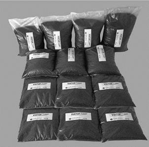
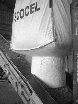
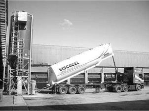
Loose fibers are packed in self-shrinkable plastic bags. They are thrown into a mixer intact and the film melts into the binder during mixing. Granulated cellulose fibers may be bagged like other fibers (Figure 4.7) or packed in big-bags (Figure 4.8). Both loose and granulated fibers can be supplied in autotankers (Figure 4.9).

image35

FIGuRE 4.7 Granulated stabilizer in PE bags of various mass—from 3 to 10 kg. (Photo courtesy of J. Rettenmaier and Sohne GmbH + Co. KG, Germany.)

image36

FIGURE 4.8 Dosing method of granulates—emptying a big-bag onto a conveyor belt. (Photo courtesy of Excel Industries Ltd., U. K.)


image37

FIGURE 4.9 Tractor-storage bin unit loaded with granulated stabilizer. (Photo courtesy of Excel Industries Ltd., U. K.)


4.2.1.2 Summary

The following is a comparison of loose or pelletized fibers and granulated fibers:

• Loose or pelletized fibers, packed in bags of a fixed weight, are easy to throw manually into a pugmill at a batch asphalt plant, though the method is problematic for big contracts, high-output plants, and plants without semiautomatic metering. Loose fibers have their staunch fans, claiming that this type of fiber can be better distributed in a mix and that a lesser amount of them (compared with granulated products) is needed to achieve a similar effect. These fibers do not present any problems during laboratory testing, and they require no extra treatment or equipment. Their disadvantages lie in water absorption, which requires covered storage, and the necessity of manual operations at batching.

• Granulated fibers usually contain the same fibers as loose fibers, except that they have been coated with a binder (or other material), enabling production of granulated products that are 3-4 mm in diameter and 3-5 mm long. The binder coating makes them more water resistant (i. e., less moisture-sensitive). Another advantage of granulated fibers is the option of automatic dosage into the mixer at an asphalt plant, usually through a screw-pneumatic feeder. Granulated fibers do require a suitable tem­perature and mechanical mixing to release them and allow them to be dispersed properly in the SMA during production, so granulated products must be added at the right moment and mixed properly.

• Another significant issue that should be considered is the susceptibility of fibers to water. It is little wonder that a stabilizer absorbs water if it is meant to absorb binder. A wet stabilizer may harm the mixture considerably (see Chapter 11). Loose fibers or pellets are more sensitive to moisture than the coated granulated products.

• Various combinations of fiber blends have been appearing here and there (e. g., cellulose-mineral and cellulose-polymer). Some of them reveal cer­tain additional features, such as building up the mastic and enhancing its shear strength.

• The amount of fibers in a mix are determined using Schellenberg’s method or other methods (see Section 4.5 and Chapter 8), normally at a level of

0. 3-0.4% (m/m).

Granulated Fibers

Granulated products (Figure 4.6a and b) are produced by coating fibers with a binder or other binder-soluble agents. A binder coating enables control of the forces on fibers during granulation and separation of individual fibers, which is necessary for distributing them evenly in an SMA mix.

The granulated form of these products makes dosage at production easy. The fiber granules are supplied in big-bags or autotankers and are stored in the bags or silos. Automatic loading with screw-pneumatic feeders is also possible.

Special attention should be paid during the preparation of laboratory samples. Due to compression of the granules during production, a higher shear force is needed to distribute the fibers; therefore one should use a mechanical mixer. If samples must be mixed by hand, it is recommended to warm the granulated product in an oven to a temperature above the softening point of the coating agent. Otherwise the stabilizer will not work effectively in laboratory samples, possibly leading to unrealistically high-binder draindown.

Granulated products are the best options for SMA production at medium and large-capacity asphalt plants because of the ease of handling.

4.2.1.1 Granulated Cellulose Fibers with Additives

Several mixtures of cellulose fibers and various modifiers are also available. These types of compounds have been produced with two goals in mind—binder stabiliza­tion and a change in the specific characteristics of a mix (e. g., workability or dura­bility). These compositions enable the simultaneous feeding of mixtures with fibers and additive. The effectiveness of such products should be tested in the laboratory to confirm the final properties of the asphalt mixture.

Can a Vintage Home Be Energy Efficient?

■ BY BETSY PETTIT

Подпись: process because many of them have under-gone numerous renovations over the years. You never know exactly what you'll find. In Old Houses, Most Systems Are at the End of Their Useful Life A hundred years can take its toll on infra-structure, and this is often the case with old houses. The water line from the street, electrical wiring, plumbing, mechanical systems— all are often nearing the end of their life. It would be foolish to renovate a house without replacing these basic systems. Windows often no longer function as intended, either. Their ventilation properties are hindered by layers of paint, or they simply became swollen shut years ago. If neglected, siding can need repair or replacement, too. While the shape, floor plan, and details of an old house allow it to endure, people often think they need an addition to provide In America, there are around 58 million houses that were built before the last energy crisis. Because these pre-1970s houses have little or no insulation, they are all ripe for energy-efficiency improvements. Houses eat up 20% of the energy used in this coun­try and account for 21% of the carbon diox­ide that contributes to global warming. This adds up to a huge opportunity.

America’s old houses can be made much tighter and can even approach net-zero energy use. Here, I’ll highlight three houses that my company, Building Science Corp., has renovated. Each house had different limitations and learning curves. I share one of the houses with my husband and business partner, Joe Lstiburek, and two of them have been used as our office space.

Renovating an old house is an expensive process. It’s also a delicate process because the end product must retain its charm. Most old houses are still around because people love their timeless form, floor plan, trim, de­tails, and historical significance. Renovating an old house is a surprising and challenging

Can a Vintage Home Be Energy Efficient?

another bathroom, bedroom, office, or bet­ter views. Then they spend money building an addition, only to spend all their time in this new space because the rest of the house is uncomfortable. They don’t really get more space in this deal; they get a smaller space that’s comfortable.

FOOTINGS AND FOUNDATIONS

Because the foundation transfers the weight of the house to the soil, prudent engineering principles and calculations are necessary. However, prescriptive code requirements often codify the worst case situation, adding unnecessarily to costs for all founda­tions built in an area. The optimum foundation will depend on factors such as climate, soil, topography, and building loads.

Basically, concrete footing widths are determined by total design loads in pounds per linear foot of footing and allowable soil bearing capacity in pounds per square foot. Column footing sizes are determined by total design load in pounds and allowable soil bearing capacity in psf. See Tables 1 and 2.

Table 1

Footing Widths, in Inches, or Typical Single Family Dwelling Loads

Design Load Allowable Soil Bearing Capacity, psf

lbs./lf footing

1500

2000

2500

3000

1,000

8

6

5

4

1,500

12

9

8

6

2,000

16

12

10 ‘

8

2,500

20

15

12

10

Table 2

Column Footing Size, in Inches, for Typical Single Family Dwelling Loads

Design Load in lbs. Allowable Soil Bearing Capacity, psf

‘ 1500

2000

2500

3000

5,000

22×22

19×19

17×17

16×16

10,000

31×31

27×27

24×24

22×22

15,000

33×33

30×30

27×27

20,000

34×34

31×31

As shown in the above tables, if soil bearing tests are made, footing widths may be reduced substantially thereby reducing costs, assuming local codes are performance based.

FOOTINGS AND FOUNDATIONS

FOOTINGS AND FOUNDATIONS

Monolithic slab – no footing


The 1986 CABO One and Two Family Dwelling Code prescribes minimum footing widths and depths, but Section R-108, Alternate Materials and Systems, provides a mechanism for innovative design and material usage. All major model codes have similar provisions that should be used whenever soil bearing tests or engineering calculations are appropriate.

Reinforcing of concrete footings is required by some local codes or is routinely installed as "local practice." Footing reinforcement is seldom necessary for footings placed on undisturbed soil. Compacted fill often has sufficient bearing capacity that makes reinforcing unnecessary.

Footings in expansive soil conditions should always be designed by qualified engineers and will most likely require
reinforcing. Otherwise, elimination of footing reinforcing rods is a legitimate method of reducing costs in many cases.

As with footings, reinforcement in foundation walls is seldom necessary in nonexpansive soil and in areas outside of seismic zones 2, 3 or 4. If rein­forcement is routinely installed in accordance with local code require­ments or local practice, it will be worthwhile to examine soil conditions and work toward change.

Under stable base conditions, concrete slab floors do not require welded wire mesh. It is not recognized as struc­tural reinforcement and provides no significant function. If installed correctly (in the upper third of the slab), welded wire mesh may be of minor value in limiting the width of cracks.

FOOTINGS AND FOUNDATIONS

Since mesh is seldom installed correctly, and since properly placed < control joints localize cracks, and ‘ since carpet or resilient flooring cover cracks, welded wire mesh is of dubious value in most cases. A survey conducted for NAHB in 1984 indicated that about 60 percent of the code jurisdictions do not require mesh in slabs.

Most major model codes require 3 1/2- inch or 4-inch thick concrete slabs – on-grade. Because the slab is 100 percent supported on compacted fill and because normal house loadings are relatively light, a 2 1/2-inch thick slab may be more than adequate on soils with high bearing capacity.

The pressure treated wood foundation

is a proven cost effective alternative
to masonry in some areas. As with all foundation systems, the realization of full performance potential requires proper attention to design, fabrication, anti installation.

Wood foundations, marketed under the name "Permanent Wood Foundations," have been used successfully in many areas of the country. They are built basically like exterior walls using lumber and plywood treated to American Wood Preservers Bureau FDN standard. Details of the system are available from the National Forest Products Association (NFPA), 1250 Connecticut Avenue, NW, Washington, DC 20036. NFPA is also investigating pressure treated wood for expansive soil applications, especially for crawl space foundations.

Waterproofing

Throughout the years, there have been many attempts to develop the defini­tive basement waterproofing method. Some methods have worked better than others, but basement leakage continues to be one of the most common customer complaints.

Capillary water and condensation on

comparatively cool walls and floors create dampness. Most capillary problems diminish or go away when concrete completely cures or when positive drainage steps are taken. A plastic film vapor barrier under the basement slab and on walls reduces capillary action through the concrete. Condensation dampness is a function of internal humidity and temperature difference between air and surfaces. When the dew point is reached, water vapor changes from a gas to a liquid. The most consistent and major problem is the hydrostatic lateralpressure of groundwater which seeks out cracks m concrete or mortar joints.

Elastomeric compounds applied to the exterior surface of the foundation wall help reduce the problem. In addition, dram tile set in gravel around the exterior basement perimeter (French drain) helps to some degree. Parging alone is practically ineffectual. Substitution of plastic films for parging and many of the so-called "sealants" has, in some cases, been effective.

Good drainage starts by keeping rain and melting snow away from the foundation by proper surf ace grading.

A 1-inch rainfall on an 1,800 square – foot roof will generate about 1,125 gallons of water. Add the water that falls within a few feet of the founda­tion and the drainage from patios, porches, driveways, etc., and the potential for basement leakage is veiy high unless most of the water has been removed before it has a chance to percolate near the house.

Gutters and downspouts are helpful if the downspouts direct water far away from the foundation. If not, water is concentrated in one area, increasing the probability of leakage at that point. In addition, settling of backfill allows water collection alongside the foundation walls. By paying careful attention to surface grading, founda­tion waterproofing is simplified.

Many new drainage boards, panels, fabrics, and plastic mesh products have been developed recently that are applied to the exterior foundation wall and relieve hydrostatic pressure by draining away water. Some were developed for highway and commercial building construction and have been proven effective. Some even have integral insulation laminated with filter fabrics and water retardant facings.

All these products are based on the fact that lateral water pressure is the culprit in most leaky basements. The major drawback of most systems is that water which has drained down has no place to go once it gets there. Drain pipe that simply circles the foundation perimeter can fill up quickly with water and then eventually silt. Water starts backing up the foundation wall, recreating hydrostatic pressure.

The NAHB/NRC developed a water­proofing method in about 1965 that still works. It relieves the hydrostatic pressure by allowing water to drain in the path of least resistance ~ down. The system does not stop at the footing, however. It provides a method which keeps the water away from the foundation wall permanently.

The system is used with the pressure treated wood foundation but was originally developed for use with concrete and concrete block founda­tions. The system lets water drain under the basement floor in a controlled manner where it can either drain into the soil below the slab or into a dry or wet sump. The system is described in detail in Basement Water Leakage.. Causes, Prevention, and Correction, available from NAHB, 15th and M Streets, NW, Washington, DC 20005.

Good supervision and construction practices are very important in waterproofing the foundation.

Cleaning the footing prior to placing the foundation wall; using care in placing concrete to prevent entrapped air or aggregate segregation; placing concrete at least 4 feet per pour; vibrating concrete; using low slump concrete; and providing drains for window and door wells all help to reduce leakage problems.

зо


TRANSPORTATION DEVELOPMENT PROCESS

2.1.1 Statewide Systems Planning

The beginnings of any roadway project involving government money are found in a statewide transportation planning program. The state transportation department devel­ops a set of goals and objectives which take into account social, economic, environ­mental, and developmental goals of other state, federal, and local agencies. Based on these goals and objectives, the department identifies transportation improvement needs throughout the state. The approach is from a multimodal standpoint; that is, not just highways are considered, but all forms of transportation, including public trans­portation, railroads, water, aviation, bikeways, and pedestrian ways (Ref. 6).

2.1.2 Transportation Programming Phase

In order to evaluate various projects from various parts of the state, information is col­lected consisting of the following items: transportation inventories, traffic analyses, modal forecasts, future system requirements, levels of service, population data and fore­casts, land use inventories, public facilities plans, and basic social, economic, and envi­ronmental data. This information comes from various sources, both public and private, is updated on a regular basis, and is used in developing the state’s transportation improvement program.

The statewide fiscal program is also considered in developing the plan. Transportation investment, fiscal forecasts, and consideration of expenditure tradeoffs between modes are some of the financial considerations affecting the project selection process.

Public input is sought from regional to local levels. Local and regional planning organizations, as well as private individuals, have a chance to express opinions and provide input to the project selection process. Once all factors have been evaluated, the state announces and publishes its recommended transportation improvement plan. This usually consists of a one-year plan and a five-year plan, with remaining projects grouped under long-range plans.