The Science of Nailing Clapboards

Even though clapboard nailing isn’t rocket science, four carpenters will give you five opinions on how to do it. Here’s what you need to know:

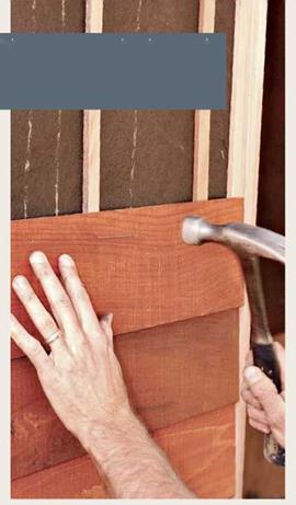
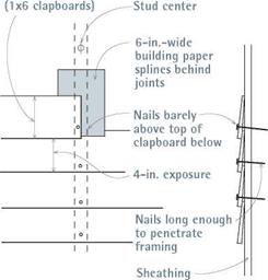
► Place clapboard nails roughly l1/ in. from the bottom so they don’t enter the tip of the clapboard underneath, especially if you’re installing 1×8 clapboards or wider. Wide clap­boards are particularly likely to split if they are inadvertently nailed at top and bottom.

► Nail clapboards to stud centers. For guidance, snap vertical chalklines on the building paper over the stud centers; offset the clapboard butt joints by at least 32 in.

Lined-up nails look better, especially if you’re using a clear finish.

► Carpenters set nails; painters fill and paint them. Setting nails makes painters cranky, and if there are 1,000 to set, painters will miss some.

image294image295image296Rain-Screen Walls

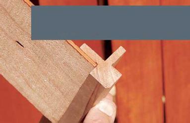
Подпись: Note the rain-screen corner-stop. These clapboards were too thin (7/i6 in., butt end) to miter, and the builder didn’t want corner boards. So a clever carpenter fashioned this corner-stop with his table saw. The stop legs are the same thickness as the furring strips affixed to the wall studs. To avoid splits, the corner-stop was predrilled and attached with stainless-steel screws.

In humid regions where housewrap and back – primed siding are not enough to prevent rotted siding, some builders have retrofitted rain-screen walls to remedy paint failure and soaked sheathing. Basically, rain-screen walls employ furring strips to space clapboards out from the building-paper membrane, allowing air to circulate freely behind the siding and dry it out. The reasoning is sound, and field reports are encouraging.

As sensible as this solution is, it’s not for every renovation. Rain screens require careful detailing and a skillful crew. For example, if furring strips raise the siding roughly 3/ in., existing trim needs to be oversize already (5/4 stock) or built up to compensate for the increased thickness of siding layers. Another option: Home Slicker®, or CedarBreather, a thin layer of nylon mesh, raises siding off the building paper and doesn’t need furring strips.

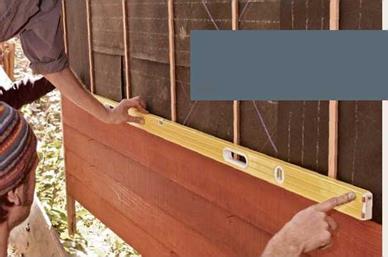
As with any horizontal siding, level each course of clapboards. Note that the corner board is installed long; it will be trimmed flush with the bottom courses of siding after the two adjacent walls have been sided.

Rain-screen walls allow air to circulate behind the siding, thereby allowing its back face to dry thoroughly. Here, thin wood furring strips raise the siding above the building paper; each strip is centered over a stud.
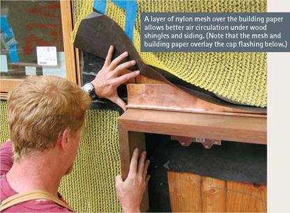
image297

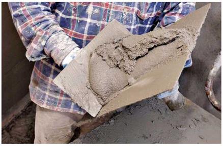
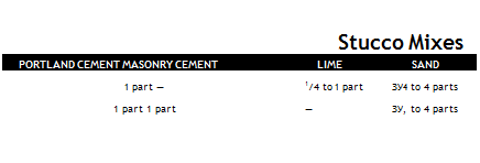
Подпись: Don't use plastic housewrap as a membrane beneath stucco. Otherwise, stucco in contact with housewrap will bond to the housewrap, filling its pores and allowing water to pass through it via capillary action. Stucco also contains surfactants (surface- active substances) that reduce the water-shedding qualities of housewrap. llll Подпись: The perfect stucco mix is stiff enough to retain a trowel mark yet loose enough to slump into a loose patty when dropped from a height of 1 ft. This mason is using his trowel (left) to load stucco mix onto his hawk, which he'll carry to the wall. With a trowel, he'll apply the mix in sweeping motions.image298Подпись: Stucco Mixes PORTLAND CEMENT MASONRY CEMENT LIME SAND 1 part — 1/4 to 1 part ЗУ4 to 4 parts 1 part 1 part — ЗУ, to 4 parts

STUCCO REPAIRS

Stuccoing a whole house requires skills that take years to learn, but stucco repairs are well within the ken of a diligent novice. If you spend a few hours watching a stucco job in your neighbor­hood, you’ll pick up useful pointers.

A basic description. Stucco is a cementitious mix applied in several layers to a wire-lath base over wood-frame construction or to a masonry surface such as brick, block, or structural tile. Like plaster, stucco is usually applied in three coats: (1) a base (or scratch) coat approximately h in. thick, scored horizontally to help the next coat adhere; (2) a brown coat about % in. thick; and (3) a finish coat (called a dash coat by old – timers) % in. to 14 in. thick. For repair work and masonry-substrate work, two-coat stucco is common.

The mix. The mix always contains Portland cement and sand, but it varies according to the amount of lime, pigment, bonders, and other agents, which are described in the following text. See "Stucco Mixes,” below, for standard mixes.

The consistency of a mix is easy to recognize but hard to describe. When you cut it with a shovel or a trowel, it should be stiff enough to retain the cut mark yet loose enough so it slumps
into a loose patty when dropped from a height of 1 ft. It should never be runny.

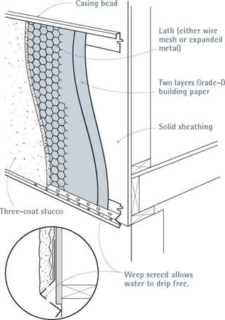
Building paper. Stucco is not waterproof. In fact, unpainted stucco will absorb moisture and wick it to the building paper or sheathing under­neath. Always assume that moisture will be pres­ent under stucco, and apply your building paper accordingly.

Basically, you want to cover the underlying sheathing with two layers of building paper before attaching the metal lath. Two layers of Grade D building paper will satisfy most codes, but you’re better off with two layers of a fiber­glass-reinforced paper such as Super Jumbo Tex 60 Minute. Although 60-minute paper costs more, it’s far more durable. Typically, the stucco sticks to the first layer of paper, exposing it to repeated soakings till it largely disintegrates; the second layer is really the only water-resistant one, so you want it to be as durable as possible.

Take care not to tear the existing paper around the edges of the patch. Tuck the new paper under the old at the top of the patch, over­lapping old paper at the sides and bottom of the patch. If the old paper is not intact or the shape of the patch precludes an easy fit, use pieces of reinforced flashing paper as "shingles,” slipping them up and under the existing stucco and paper and over the new. Caulk new paper to old at the edges to help keep water out.

Lath. Metal lath reinforces stucco so it’s less likely to crack and also mechanically ties the stucco to the building. Lath is a general term; it encompasses wire mesh or stucco netting (which looks like chicken wire) and expanded metal lath (heavy, wavy-textured sheets). When nailing up wire mesh, use galvanized furring nails with a furring "button” that goes under the mesh. When you drive these nails in, you thus pinch the wire mesh between the nail head and the button, creating a space behind the mesh, into which the scratch coat oozes, hardens, and keys. Note: Don’t use aluminum nails, because cement corrodes them. Use about 20 nails or staples per square yard of lath, spacing nails at least every 6 in. Overlap mesh at least 2 in. on vertical joints, and extend it around corners at least 6 in.

Expanded metal lath is a thicker, stronger lath used in situations requiring greater strength—for example, to cover soffits, where you’re fighting gravity while applying stucco. That is, expanded metal lath won’t sag. It typically comes in 2-ft. by 8-ft. sheets, is somewhat more work to install, and costs more. Expanded metal lath is stapled or nailed up; no need for furring nails because it’s self-furring.
Подпись:
Подпись:image300image301

Base coat. Here’s how to apply the base (scratch) coat:

1. Cover the sheathing with building paper and attach the lath.

2. Establish screed strips, which are guides for the stucco’s final surface thickness. Screeds can be existing window edges, corner boards, or strips manufactured for this purpose.

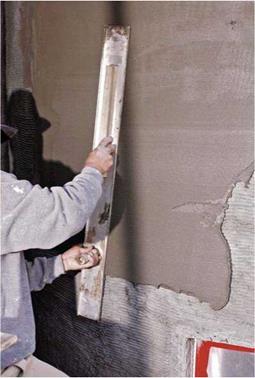
3. Mix and trowel on a thick first coat, press­ing it to the lath.

4. When the mud has set somewhat, screed it (meaning get it to a relatively uniform thickness) using screed strips as thickness guides.

5. Even out the surface further with a wood – or rubber-surfaced float.

6. Press your fingertips lightly against the surface; when it is dry enough that your fingers no longer sink in, steel trowel the surface. Steel troweling compacts the material, setting it well in the lath and driving out air pockets.

7. Scratch the surface horizontally.

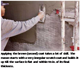
Brown coat. Installing the brown (second) coat requires the most skill, care, and time because this stage flattens the surface and builds up the stucco to within Z in. of its final thickness.

To apply the brown coat, trowel on the stucco, screed it to a relatively uniform thickness, float the surface further, and steel-trowel to improve the uniformity. Then roughen the surface slightly with a wood or rubber float. As the stucco sets up, you will be able to work it more vigorously to achieve an even, sanded texture that will allow the finish texture coat to grab and bond. Do not leave the brown coat with a smooth, hard – troweled surface. Otherwise, the finish coat won’t stick well.

Finish coat. The finish coat is about!/ in. thick, and textured to match the rest of the building.

I Stucco Details

Подпись: Foil-faced, self-adhering flexible flashings such as Foilastic® are ideal for sealing the tops of window and door head casings. Metal flashing, the traditional choice, expands and contracts over time, encouraging leaks; and any nails above the head could leak. Peel-and-stick flashings need no nails and grip tenaciously, sealing out leaks. 1111 Подпись: PROГ І P Two ways to reduce stucco shrinkage cracks: (1) Add nylon fiber to the scratch coat. (2) After the top stucco coat has cured at least 3 weeks, paint it with an elastomeric paint, which flexes as materials expand and contract. Подпись: llllПодпись: DiagnosinПодпись: Here are some common symptoms of stucco problems and their probable causes. ► DIAGONAL CRACKS from the corners of door or window trim indicate a shifting foundation; call a structural engineer. ► CRUMBLING STUCCO along the base of a wall suggests standing water and probable deterioration of the sheathing. Cut back the damaged area and install a weep screed so water can exit. ► LARGE PATCHES FALLING OFF suggest faulty flashing, rotted sheathing, or lath that's insufficiently attached. Note: If you see a shiny surface beneath a section of stucco that fell off, the installer likely waited too long to apply that coat, mistakenly letting the bonder dry. In this case, roughen the surface with a chisel before applying new bonder and a stucco patch.

When attempting to match an existing texture, you may need to experiment. If at first you don’t achieve a good match, scrape off the mud and try again until you find a technique that works. Textures are discussed at the end of this stucco­ing section.

Stucco trim. If doors or windows in stucco walls are cased with wood trim, flash their head cas­ings with self-adhering flexible flashing. Metal windows in stucco usually have no casing to dam up water and so need no head flashing; metal windows usually have an integral nailing flange that serves as flashing after being caulked. If you need to cut back stucco siding to repair rot or install a new window, install flexible flashing over the head casing, and install fiberglass-reinforced paper along the sides and under the sill.

Helpful materials. The following materials are particularly useful for repair work and are avail­able from any masonry supplier.

► Weep screed is a metal strip nailed to the base of exterior walls, providing a straight edge to which you can screed stucco. Because it is perforated, it allows moisture to "weep" or migrate free from the masonry surface, thus allowing it to dry thoroughly after a rain.

Weep screeds are an easy way to make the bottom edge of stucco look crisp and clean.

And because the weight of the stucco flattens the screed down against the top of a foundation, the screed provides a positive seal against termites and other pests. (Stucco’s tendency to retain moisture makes rot and insect infestation particular problems.) Weep screed is also a good solution for the frequently rotted intersection of stucco walls and porch floors.

Weep screed isn’t difficult to retrofit, but you’ll need to cut away the base of walls 6 in. to 9 in. high in order to flash the upper edge of

g STUCCO PROBLEMS

the screed strip properly. Cut the screed with aviation snips, and fasten it with large-head 8d galvanized nails.

► Wire corners are preformed corners (also called corner aid) that can be fastened loosely over the wire lath with 6d galvanized nails.

Set the corner to the finished edge, taking care to keep the line straight and either plumb or level.

► Latex bonders resemble white wood glue. They are either painted into areas to be patched or mixed into batches of stucco and troweled onto walls. To ensure that the mixture is dis­tributed uniformly, stir the bonder into water before mixing the liquid with the dry ingredi­ents. Reduce the amount of water accordingly, as recommended by the manufacturer.

To ensure that a patch will adhere well, brush bonder full strength all around the edges of the hole or crack you’ll fill with new stucco. Merely applying patch stucco without bonder creates a "cold joint," which is likely to frac­ture. In most cases, you must apply new stucco before the bonder dries; otherwise, the joint won’t be as strong, although products such as Thorobond® and Weldcrete® will reemulsify when moistened by the next stucco coat.

► Prepackaged stucco mix is helpful because it eliminates worry about correct proportions among sand, cement, and plasti­cizing agents. However, you will need to add bonder to the mix.

► Color-coat pigment (also known as LaHabra™ color or permanent color top coat), is a pigmented finish coat, available in a lim­ited range of colors. Its principal advantage is its ease of mixing and its depth of color, which is as deep as the finish layer. But precolored top coats usually aren’t of much use to reno­vators because their colors aren’t likely to match older colors on a house. Yet, if a house is already painted white, white pigmented stucco will require fewer coats of paint to blend in.

► Masonry paint and primer, which is alkali resistant, can be used on any new masonry surface. You should still wait at least 2 weeks or 3 weeks for the stucco to "cool off" before painting it. (Follow the manufacturer’s recommended wait times.) Use two coats of primer and two coats of finish paint.

The repair. Before repairing damaged areas, first diagnose why the stucco failed. Then deter­mine the extent of the damage by pressing your palms firmly on both sides of the hole or crack. Springy areas should be removed. Continue pressing till you feel stucco that’s solidly
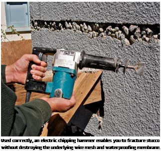
Подпись: Used correctly, an electric chipping hammer enables you to fracture stucco without destroying the underlying wire mesh and waterproofing membrane. Подпись: A ragged edge is easier to disguise than a straight line when applying repair stucco. So, when using a hand chisel or a chipping hammer, make your fracture lines meander. A rough edge also helps hold the patch in. For this reason, don't use a diamond blade in a circular saw to cut out stucco. Besides, a circular-saw blade is too likely to cut through the wire mesh and the waterproofing membrane.Подпись: 1111

attached. When removing damaged areas, be deliberate and avoid disturbing surrounding intact stucco. Avoid damaging existing lath so you can attach new lath to it. Also avoid ripping the old building paper if possible. Safety note: Whether removing old stucco or mixing new, wear eye protection, heavy leather gloves, and at least a paper dust mask.

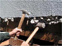
You can use a hammer and a cold chisel to remove a small section of damaged stucco. But for larger jobs, rent an electric chipping hammer with a chisel bit. Important: The bit should just fracture the stucco, not cut through it. Ideally, the underlying wire mesh and building paper will remain undamaged.

Let’s say you’re removing stucco to expose a rotted mudsill. Using a chipping hammer, fracture the stucco surface in two roughly parallel lines. On the first pass, delineate the top of the stucco to be removed. Then make a second pass, 6 in. lower. Basically, you’ll eventually demolish all the stucco below the top cut-line and restucco it after you replace the mudsill. But if you carefully remove the top 6 in. of the damaged stucco, you’ll preserve the wire mesh in that section, giving you something to tie the new mesh and stucco to.

Cut through the wire mesh exposed by the second pass, insert a pry bar under the stucco, and pry up to detach the stucco from the sheath­ing. Because the first pass of the chipping hammer separates damaged stucco from intact stucco, prying up this 6-in. corridor of stucco will not disturb the solid areas above it.

Now the strenuous work begins. Using a mason’s hammer or a beat-up framing hammer, carefully pulverize the corridor of pried-up stucco.

Stucco is hard stuff, so whacking it in place with a hammer is more likely to drive it into the wood sheathing than to pulverize it. However, if you pry up the stucco slightly, you can slide a hand sledge under it to serve as an anvil. Then, between a hammer and a hard place, the stucco will shatter nicely. After you’ve removed all old chunks of stucco, you’ll have a 6-in.-wide section of unen­cumbered wire mesh and, ideally, a layer of largely intact building paper under that. Once you’ve replaced the rotted framing (and sheathing), insert new paper, tie new mesh to the old—just twist the wire ends together—and nail both to the sheathing. Now you’re ready to apply the new scratch coat.

If only the finish coat is cracked, wire brush and wet the brown coat, apply fresh bonding liq­uid, and trowel in a new finish coat. But if the cracks are deeper, the techniques for repair are much the same as those for patches, except that you need to undercut the cracks. That is, use a cold chisel to widen the bottom of each crack. This helps key in (hold) the new stucco. Chip away no more than you must for a good mechan­ical attachment. Then brush the prepared crack well with bonding liquid.

Texturing and finishing. To disguise new stucco patches, it’s often necessary to match the texture of the surrounding wall. Before texturing the fin­ish coat, steel-trowel it smooth and let it set about a half hour—although the waiting time depends on temperature and humidity. Cooler and more humid conditions delay drying. Stucco allowed to cure slowly is far stronger than fast – cured stucco. So, after applying the finish coat, use a hose set on a fine spray to keep the stucco

image303

To remove stubborn chunks of old stucco from the wire mesh, pry up the mesh enough to slide the head of a hand sledge underneath so it can serve as an anvil. Hammered stucco will then pulverize. Wear eye protection and a paper respirator mask.

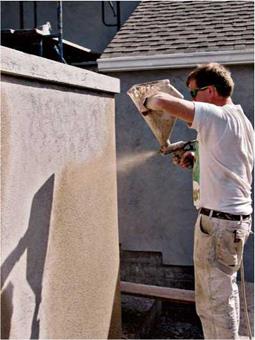
image304Подпись: After completing the repairs, texture the wall to blend the patch to the surrounding stucco. Here, plastering cement, LaHabra color, and water were mixed repeatedly, poured into a hopper, then sprayed onto the wall to create a stippled effect.

damp for 3 days. Here are descriptions of the three com­mon textures:

► Stippled. For this effect you’ll need rubber gloves, an open-cell sponge float like those used to spread grout in tiling, a 5-gal. bucket, and lots of clean water.

After dampening the sponge float, press it into the partially set finish coat and quickly lift the float straight back from the wall. As you lift the float, it will lift a bit of the stucco material and so create a stippled texture looking somewhere between pebbly and pointy. Repeat this process over the entire surface of the patch, feathering it onto surround­ing (old) areas as well, to blend the patch in.

Rinse the float often. Otherwise, its cells will pack with stucco, and the float won’t raise the desired little points when you lift it. Equally important, the sponge should be damp and not wet. If you want a grosser texture than the float provides, use a large open-cell natural sponge. If you notice that the new finish is more pointy than the old surrounding stucco, that’s probably because the old finish has been softened by many layers of paint. To improve the match, knock the new texture down a little by lightly skimming it with a steel trowel.

► Swirled. Screed (level) the patch’s finish coat to the surrounding areas, and feather it in. After you’ve made the patch fairly flat, comb it gently with a wet, stiff-bristled brush. For best results, use a light touch and rinse often; otherwise you’ll drag globs of stucco out of the hole. By varying the pressure on the brush, you can change the texture.

► Spanish stucco or skip troweled. Visually, this texture looks rather like flocks of amoebas or clouds. To achieve this look, screed off the patch so it’s just Иб in. below the level of surrounding areas. Then, using a steel trowel, scoop small amounts of stucco off a mortarboard and, with a flick of the wrist, throw flecks at the wall. Skim the flecks with a swimming pool trowel because its rounded edges are less likely to gouge the stucco as you flatten the flecks slightly.

Ideally, this will give you an irregular pat­tern of miniature mesas, matching that of the original surface. Another approach is to use a
wet, sandy mix and load it onto your steel trowel unevenly. (Beforehand, coat the hole well with bonder so the new material adheres well.) Again, using a swimming pool towel, you’ll see the material "skipping" over the sand particles, leaving flattened patches of texture and gaps. To get the right texture, you’ll need to experiment with trowel pres­sure, mix stiffness, and wrist movement.

General Principles and Some Theory

The principles of designing an aggregate mix and then the content of binder are presented in Figure 7.12. It is an illustration of a telescopic[37] method of creating SMA, which involves inserting consecutive elements into free space (air voids) in a compacted component of a larger size. In other words:

• A volume of fine aggregate is inserted into the air voids in the compacted coarse aggregate skeleton with the effect of increasing the air voids among the coarse aggregates (enlarging effect).

• A volume of filler particles is inserted into the air voids in the compacted fine aggregate.

• A volume of binder is introduced into the air voids in the compacted filler.

• The free space remaining after inserting all these elements produces the content of air voids in a compacted SMA.

Voids Enlarging effect

Filler

Binder + stabilizer

FIGURE 7.12 Placing consecutive elements of SMA in a mixture. (From Voskuilen,

Ideas for a volumetric mix design method for Stone Mastic Asphalt. Proceedings of the 6th International Conference Durable and Safe Road Pavements, Kielce [Poland], 2000. With permission.)

Filling the air voids with the subsequent elements has already been partially dem­onstrated and discussed when explaining the concept of air voids in a filler (see Chapter 3).

Determining the density of all the SMA components is the basis of the design activity because the Dutch method is a volumetric-type method.

BRIDGE DESIGN SPECIFICATIONS

AASHTO Specifications. For many years, the basic manual for design of highway bridges has been the Standard Specifications for Highway Bridges adopted by the American Association of State Highway and Transportation Officials (AASHTO). These specifications permit use of either allowable stress design or load factor design. In 1994, however, AASHTO published a completely new alternative volume, LRFD Bridge Design Specifications. It was subsequently updated with a second edition in 1998; third edition in 2004; fourth edition in 2007; and annual Interim Specifications thereafter. Based on the load and resistance factor design method, the LRFD Specifications represent a major step in improved bridge design and analysis methods. It is anticipated that usage of the new specifications will lead to bridges with improved serviceability, enhanced long-term maintainability, and more uniform levels of safety. The initial volume resulted from a 5-year research effort conducted under AASHTO’s National Cooperative Highway Research Program. Independent consultants, technical representatives from various industries, AASHTO members, and other engineers par­ticipated in the effort to develop a draft document. Then the provisions were tested in trial designs at 14 AASHTO member departments before final specifications were adopted. One of the most useful feature included is a detailed commentary that explains the specification provisions and gives references for further study.

The use of the new specifications has been increasing throughout the country. The Federal Highway Administration (FHWA) and AASHTO have established a goal that the LRFD Specifications be used for all new bridges designed after 2007 and for all culverts, retaining walls, and other standard structures after 2010. Most state DOTs have adopted LRFD specifications for the design of their bridges so as not to lose funding for federally funded bridge projects. States unable to meet these dates were required to provide justifi­cation and a schedule for completing the transition to LRFD. The Standard Specifications would be applicable only to structures designed prior to 2007, and could be used for the maintenance and rehabilitation of existing bridges. No technical revisions will likely be made to the Standard Specifications in the future as its usage is phased out.

AASHTO specifications are developed under the direction of the AASHTO Highway Subcommittee on Bridges and Structures. This subcommittee consists of all bridge engineers of states of the United States and of Canadian provinces and officials of selected turnpike and bridge authorities. The specification development process is a deliberate one. Nevertheless, changes are made on a regular basis (some would say too frequently for the average bridge designer to stay abreast of them). Between new editions, revisions are published under the title of Interim Specifications. When identifying the AASHTO specifi­cations used for design on plans, some states refer to “AASHTO Standard Specifications for Highway Bridges, Current Edition.” A better practice is to refer to the specific edition, by number and year, along with any interims that were in effect at the time of design.

Unless there is a cogent reason for not meeting the minimum requirements of the AASHTO specifications, engineers designing bridges where they are in effect should apply and conform to them. Any exceptions should be noted on the plans. In case of litigation, one would have to explain why these recognized standards were not met.

Other AASHTO Publications. AASHTO offers numerous publications related to bridges and structures. A bridge designer should be aware of the availability of these publications and should use them where applicable.

In this chapter, references to the “AASHTO Specifications” or “AASHTO” will be to the AASHTO Standard Specifications for Highway Bridges unless otherwise noted.

Bridge Design Manuals. Many state departments of transportation publish bridge design manuals, which they develop for guidance of their own staff and consultants. States that do not have manuals often publish design memoranda. Before starting a bridge design project, a consultant should determine which of these aids are available, acquire and become familiar with them, and apply them in designing and preparing plans. Some state bridge design manuals are quite explicit, and are almost textbooks on bridge design.

INSTALLING WOOD SHINGLES

Before you start shingling, make sure that win­dows and doors are correctly flashed, that sheathing is covered with building paper—most pro shinglers prefer 15-lb. felt paper—and that exterior trim is installed.

Materials. For best results, use No. 1 grade cedar shingles. For a standard 5-in. shingle expo­sure, figure four bundles per square (100 sq. ft.). Always inspect the visible shingles on a bundle to make sure they’re uniformly thick (3з8 in.) at butt ends, of varying widths (on average, 6 in. to

CUTTING SHINGLES CROSS-GRAIN

12 in.), knot free, and reasonably straight grained. Installing shingles requires a lot of trim­ming, so you don’t want to be fighting knots and wavy grain. Shingle butts should also be cut cleanly and squarely across, not angled or ragged. Send back bundles that look inferior or contain mostly narrow shingles.

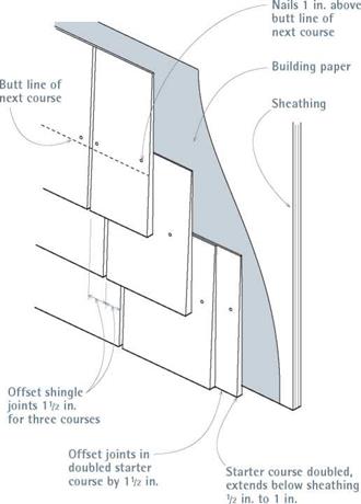
To save a little money, however, you might want to use No. 2 shingles for the bottom layer of doubled starter courses. In this case, order one bundle per 50 lineal (lin.) ft. of wall. Typically, the starter course of shingles along the bottom is doubled, with vertical joints between the two shingle layers offset by at least 1 h in.

Also, pick up a bundle to see how dry it is. Relatively wet shingles are fine, as long as they’re good quality, but they’ll shrink. In fact, most shingles shrink. Though how-to books are fond of telling you to leave a!4-in. gap between shin­gles during installation, many shinglers don’t bother; unless the shingles are bone-dry, installers assume that all shingles will shrink some.

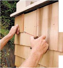
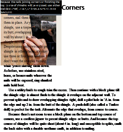
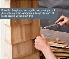
Use two 1 f4-in. galvanized nails or staples per shingle, whatever its width. Because nails must be covered by the course above, place shingle nails in M in. from either edge and 1 in. above the eventual butt line of the course above. Where nails will be visible—say, on interwoven corners or the top course below a window—use sili­conized bronze ring-shank nails or stainless-steel nails. Again, 1!4-in. nails are fine, unless you’re also nailing through a gypsum layer to reach the sheathing on a fire-rated wall.

Installation. If you’ve got a water table (see p. 132), set your first course of shingles atop it, even if it’s not level. That way you eliminate unsightly gaps along the trim, and it’s easy
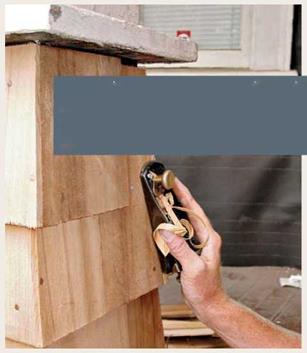
enough to level the next course of shingles. If there are corner boards, snap chalklines between them to mark shingle courses, and off you go. However, if there are no corner boards, weave shingles at the building corners, alternating shin­gle edges every other course. This requires more skill and patience than just butting shingles to the boards but produces corners that are both handsome and weather-tight. Weave the corners first; then nail up the shingles in between. Because the starter course overhangs the bottom of the sheathing 12 in. to 1 in., measure down that amount at each corner, using a laser level to establish level. After establishing the correct exposure, as described above, shingle up each corner. As you work up the wall, snap a chalkline from corner to corner to line up shingle butts.

As you did on the first course, offset the verti­cal shingle joints at least Ш in. between courses. If you have a partner, you’ll find it easier if each of you works from a corner toward the middle. Only the last shingle will need to be fitted.

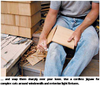
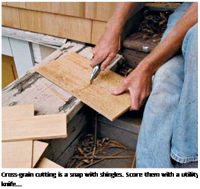
Подпись: ... and snap them sharply over your knee. Use a cordless jigsaw for complex cuts around windowsills and exterior light fixtures.
Подпись: When you weave the corners first, leveling the shingle courses in between is largely a matter of snapping chalklines between shingle butts at either end of the wall. If you snap the chalkline slightly high, as shown, the shingle butts will cover the chalk.image286image287Wood Shingle Details

Fit shingles closely to window and door cas­ings. The top of the shingle course under a win­dowsill should butt squarely to the sill. Because this course needs to be shortened and will be sus­ceptible to splits, caulk the back sides. It’s also wise to caulk the shortened top course of shingles under the eaves. Ideally, the tops of those shingles

will also be protected by a rabbeted-out or built – up frieze.

Подпись:Подпись:

Подпись: ■ ill INSTALLING WOOD SHINGLES
image289

image290If you need to angle cut shingle butts for use along gable-end walls and dormers or need to angle cut shingle tops to fit under rake trim, use an adjustable bevel to capture the roof angle and transfer it to shingles. Such angle cuts are best

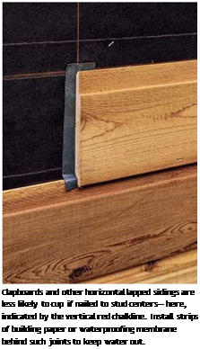
Подпись: REPLACINGПодпись: Clapboards have a planed, smooth front side and a rougher back side. Using 100-grit sand-paper, lightly sand the smooth side to help paint adhere, even if the clapboard is preprimed. 1111 Подпись: Clapboards and other horizontal lapped sidings are less likely to cup if nailed to stud centers— here, indicated by the vertical red chalkline. Install strips of building paper or waterproofing membrane behind such joints to keep water out.

made all at once, on the ground, using a table saw. To notch shingles around windowsill ears and the like, use a cordless jigsaw. Finally, leave a Я-in. gap beneath dormer-wall shingles and adja­cent roofing; otherwise, shingles resting directly on roofing can wick moisture and rot.

INSTALLING CLAPBOARDS

The following discussion assumes that you’ve read this chapter’s earlier sections on layout and that you’ve installed door and window flashing, building paper, and exterior trim. It also assumes that the building has corner boards that you can butt the clapboards to. Otherwise, the clapboard corners will require compound-miter joints, which is a considerable amount of work.

Materials. Clapboards are a beveled siding milled from redwood, red cedar, or spruce; for best results, use Grade A or better. Preprimed finger-jointed clapboards are a cost-effective alternative, joining shorter lengths of high-quality wood. Clapboards come in varying widths and thickness, but all are nominally 1-in.-thick boards that have been planed down. Thus a 1 x6 is actually Я in. thick (at the butt) by 5!4 in. wide; a 1×8 is actually Я in. by 7h in., and so on. Traditional clapboards come in varying lengths, whereas finger-jointed prod­ucts are manufactured in 16-ft. lengths; all are sold by the lineal foot.

To estimate the amount you need, calculate the square footage of your walls, less window and door openings. Then consult the table below, which assumes Я in. of overlap for 1×4 clap­boards and 1-in. to 1 J/8-in. overlap for all other sizes. It also factors in 5 percent waste. Order preprimed (or prestained) clapboards. Pre­priming seals out moisture, saves tons of time otherwise lost to priming and waiting for primer to dry, and keeps the job moving. You will need a small amount of primer on hand to touch up newly cut ends.

Clapboard Needed

to cover 100 Sq. Ft.

CLAPBOARD SIZE

LINEAL FEET

1×4

440

1×6

280

1×8

200

1×10

160

Shingles

If you split a shingle while installing it (or if you need to remove shingles to install an exhaust vent for a fan), break out the shards, hammer down the nail heads, and replace the shingle. To remove a few damaged shingles on an otherwise intact wall, use a shingle ripper (also called a slate hook), shown in the photo on p. 121. Slide its hooked head up under surrounding the shingles till you can feel it hook around a nail shank. Then hammer down on the tool’s handle till the hook cuts through the shank. To avoid damaging the replacement shingles as you drive them into place, hold a scrap block under the shingle butt to cushion the hammer blows.

Nails. Buy 5d stainless-steel, ring-shank siding nails, whether you’re painting the clapboard or not. True, stainless-steel nails cost four or five times as much as galvanized nails, but that pre­mium buys you peace of mind. Galvanized nails are fine 99 percent of the time. But if their coat­ing breaks off, the nail will rust. Moreover, the tannins in cedar and redwood can chemically react with galvanization, which causes staining. Same with galvanized staples. For every 1,000 lin. ft. of siding, buy 5 lb. of 5d nails.

Installation. Worth repeating: Standard clap­board exposure is 4 in. for 1×6 clapboards (actual width, 5Я in.), but you may want to vary that exposure by І4 in. or less between courses to help align the clapboards with the window and door casings.

The first course of clapboards typically sits atop a water table. First flash the top of the water table with metal drip-edge to forestall rot. To establish the correct pitch for that first course, rip a 1 Я-in.-wide beveled starter strip from the top of a clapboard. (Save the 4-in.-wide bottom waste rip for the top of a wall.) Tack the strip atop the water table, and you’re ready to nail up the first course. The water table may not be level, but that’s okay; better to avoid a noticeable gap between a level first course and an off-level water table. In that case, take pains to level the second and all successive courses.

Start at one corner board and work all the way across the wall, nailing clapboards to each stud center they cross. All butt joints should be square cut and centered over a stud so that the ends of both boards can be securely nailed.

Подпись: If painted clapboards outside kitchens and bathrooms chronically peel, excess interior moisture may be migrating through the siding. Add an exhaust fan, and drive plastic shims under clapboards in the affected area so moisture can exit. Worth a try. llll

I Clapboard Details

51/4 in. actual width

image292

Position clapboard joints over stud centers.

For the most weathertight joints, bevel-cut ends. Note: For clarity in this drawing, building paper between clapboards and sheathing isn’t shown.

Homemade

image293

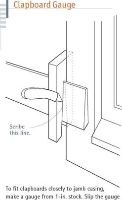
over the clapboard, slide it next to the casing, and mark the casing edge onto the clapboard.

Remember to stagger joints by at least 32 in. To further weatherproof the joints, back them with strips of building paper; the paper overlaps the top of the clapboard beneath by ‘A in.

For clean, square cuts, rent or buy a 10-in. radial-arm saw with a 40-tooth or 60-tooth carbide-tipped blade. And be prepared to recut joints. When fitting the second board of a butt joint, leave it a little long till you’re satisfied with the joint. If it isn’t perfectly square on the first try, you’ll have excess to trim.

When butting clapboards to corner boards and jamb casings, use the homemade gauge shown below at left. Using the gauge to hold the clapboard tight to the trim, scribe the cutoff line with a utility knife. Never fit clapboards so tightly to the casing that you need to force them into place: Too tight trim can cause window sashes to bind. Where top courses abut the underside of eave or rake trim, rabbet or build out the trim to receive the top edges of the clapboards, as illus­trated on p. 133. Caulk all building joints well with latex acrylic or urethane caulk before nail­ing up the top course of clapboards.

DUTCH METHOD

There is a widespread belief among many engineers that SMA, due to its peculiar­ity, should be designed by volume. The volume concept also forms the basis of an experimental method of design applied in the Netherlands.

To put it concisely, we can repeat what has been explained in the previous chap­ters of this book as follows:

• Air voids remain in the stone skeleton after its compaction.

• The volume of mastic, including the fine aggregate, filler, binder, and stabi­lizer (drainage inhibitor), has to be put into that free space.

The following description of this SMA design method includes the guidelines of 2004 and has been prepared based on information from two publications (Jacobs and Voskuilen, 2004; Voskuilen, 2000). This method was revised (simplified) in 2007; a description of the changes made is explained in Section 7.4.5.

Moisture Diffusion Coefficients

Moisture diffusion measurements are still not performed very commonly for as­phaltic materials. There are currently two main test procedures being utilized. The first is an overall measurement of the increase of weight as a sample is ex­posed to a controlled moisture conditioning (Cheng et al., 2003). The second is a slightly more complicated procedure using Fourier transform infrared spectroscopy (Nguyen et al., 1992). It is quite challenging though, to utilize the available test data, since the values can vary greatly. For instance, for the AAD-1 bitumen, values have been published ranging from 4.79 mm2/h (Cheng et al., 2003) to 9.0 x 10⁻⁵ mm2/h (Nguyen et al., 1992). Comparing these values with published diffusion coefficients of, rubber, PVC and polyethylene (Abson & Burton, 1979), the lower diffusion value for the AAD-1 asphalt binder (bitumen) seems to be more plausible. Since the mastic matrix in an asphaltic mixture generally consists of asphalt binder as well as sand particles and filler material, a higher diffusion value than for the binder alone can be expected. In the simulations described in this chapter, a diffusion coefficient of 1.0 x 10 3 mm2/h has been utilized for the mastic film.

LAYING OUT WOOD SHINGLES AND CLAPBOARDS

For clapboards and shingles, the two most important parts of the layout are establishing level for the bottom course and varying the expo­sure of subsequent courses so that they align with door or window trim, if possible. If a leveled water table has already been installed, skip the next section.

Establishing level. If there’s no water table on the house (see p. 132), the bottom of the first course of siding typically overhangs the sheath­ing by % in. to 1 in. Because the bottom edge of sheathing is seldom level, use a laser level or a water level to establish a level base line. Simple tripod-mounted laser levels are relatively inex­pensive and offer quick layout over long dis­tances without needing a helper. When set up correctly, they’re also quite accurate, usually within Уз in. in 100 ft.

Lay out the front of the building first. Pencil in an appropriate siding overhang on one corner board. Then, using the level, transfer that mark to all the other corner boards. When you’re done, use a combination square to draw light lines through your pencil marks, across the faces of the corner boards. These lines indicate cut-off lines for the corner boards and the bottom of the first course of siding. To align that first course of sid­ing, stretch a chalkline through the marks and snap it onto the building paper. Or, if you’ve used housewrap, which won’t chalk well, drive a nail into a pencil line at each corner and stretch a taut line between them. Place clapboards or shin­gle butts slightly above, but not touching, the line so it won’t be distorted.

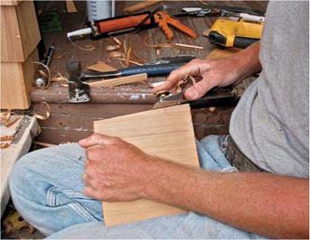
Подпись:Подпись: Wood siding is pleasant to work with and requires few specialized tools. Though power nailing has largely replaced hand nailing, there's still plenty of hand crafting and fitting to do, such as the shingle shaving shown here.image282Varying subsequent courses. By aligning siding courses to window and door trim, you can mini­mize funky-looking notch cuts at door and window
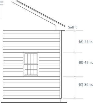
Подпись: I Aligning Siding Coursesimage283Подпись:Подпись: Cross-grain cutting is a snap with shingles. Score them with a utility knife...

corners. (But when installing wide-board siding, notch cuts are sometimes unavoidable.) Achieve these alignments by increasing or decreasing the exposure of individual courses. Of course, there are physical restrictions. For example, clapboards must overlap at least 1 in. But as long as exposure adjustments are no more than ‘/ in. between courses, they’ll look evenly spaced.

The following steps refer to the illustration above:

1. Measure the full height of the wall, from the cutoff at the base of a corner board to the underside of the soffit. Let’s say the height is 10 ft. 2 in. (for calculation purposes, 122 in.). Because shingle exposures are customarily 5 in., that wall will have roughly 24 courses.

2. The wall has three windows and a door. Fortunately, their head casings happen to align 84 in. above the base line. This creates three sep­arate areas for which shingle exposures need to be adjusted, as shown in the drawing: (A) from the top of head casings to the soffit, 38 in.; (B) from the top of the window head casing to the bottom of sills, 45 in.; and (C) from the bottom of windowsills to the base line, 39 in. Total: 122 in.

3. Calculating exposure adjustments is easy. Round off each measurement to the nearest increment of 5 in. Then increase or decrease the shingle exposure accordingly. Thus area A yields a 4%-in. exposure (38^8 = 4%); area B is exactly 5 in. (45^9); and area C is roughly 418 in.

The easiest way to keep track of such meas­urements and adjustments is by penciling them onto a story pole, a long straight board (a 1×2 is fine) whose length equals the distance between the top of the water table (if any) to the underside of the soffit or frieze. First mark the tops and bot­toms of window and door casings onto the story pole, then the adjusted course heights between.

As you work around the house, align the bot­tom of the story pole to each corner board and transfer marks from the pole to each board. If the house has windows set at varying heights, story – pole marks will better align with casing on some walls than on others; give precedence to the house’s most prominent facade. Where courses just won’t line up with casing joints, notch the siding around them.

REPAIRING EXTERIOR TRIM

Although it may be tempting to rip out exterior trim that’s badly weathered or rotten, repair is often a better option if replacement trim would be expensive or difficult to remove. Before decid­ing either way, survey the extent of the rot and address its cause. Otherwise you’re treating only the symptom.

Replacing rotted sections is a good option when the bottom of an otherwise sound trim board has rotted away. Flat and square trim is easier to replace and match than molded trim. Rotted bottoms of corner boards and splash­boards are usually easy to cut free and replace, whereas punky doorsills or windowsills are prob­ably best repaired in place, using epoxy, as described in the next section.

Replacing the bottom of a rotted board is straightforward. Draw a line across the face of the board, 6 in. above the bad section. After setting your circular-saw blade to the thickness of the board, use a Speed Square to guide the saw shoe, making a 90° cut. Wear goggles and use an old blade because it may hit nails. The replace­ment piece should be the same thickness, width, and—preferably—species as the original trim.

To join the new section to the old, use a router with a slot-cutting bit to cut a biscuit slot in both board ends. Dry-fit everything, prime all surfaces with epoxy primer, and allow the primer to dry well. Then epoxy the pieces together. Hold the boards in place with a piece of scrap screwed to both. Give the epoxy a day to cure (or whatever the manufacturer suggests), and you’re ready to sand and paint.

In-place epoxy repairs are appropriate when the rotted area is relatively small (epoxy is expen­sive!) and the trim would be difficult or costly to replace. Rotted windowsills or sashes are tough to remove because both are captured by sur­rounding elements. Epoxy applications vary con­siderably, so visit the manufacturers’ Web sites (try Abatron®, ConServ®, and Advanced Repair Technology®, for example) for specifics or get recommendations at your local home center.

Use a chisel or awl to dislodge loose, crum­bling wood. Suck up debris with a shop vacuum. Allow the wood to dry thoroughly before proceed­ing. Although it’s desirable to cut back to solid wood, soft punky wood can often be reinforced by impregnating it with a liquid consolidant. Typi­cally, you’d drill a series of small-diameter holes into the wood and then inject consolidant into them till the wood is clearly saturated. In time, the impregnated wood will become as hard as a rock.

But, for the best bond between the consoli – dant and the two-part epoxy filler that follows, apply the putty-like filler while the consolidant is still tacky. Avoid getting epoxy on your skin, and by all means wear a respirator mask with replaceable filters when applying or sanding it. After the filler dries and you’ve sanded it to its final shape, prime and paint it. Though other­wise tough, some epoxies are degraded by UV rays, and whatever original wood remains still needs protection from the elements.

Siding

This section addresses installation of the three most common traditional sidings: wood shingles, clapboards, and stucco. Vinyl and aluminum sid­ings are cost-effective alternatives to traditional sidings; they’re also durable and virtually maintenance-free if correctly installed. But they’re normally a whole-house job most effi­ciently handled by specializing contractors and so aren’t further addressed here. Aesthetics are another consideration. Although popular in new construction and renovation, faux-grained vinyl looks phony to traditional­ists. If that’s your reaction, too, consider untextured sidings, which, when painted, more closely resemble painted wood.

The information that follows assumes that building paper or plastic housewrap covers the wall sheathing and that win­dows, doors, and exterior trim are already installed.

Design Method

The SMA design procedure consists of the following stages:

• Selection of the design aggregate mix using an analysis of the impact of the coarse aggregate content on SMA properties

• Determination of the optimum design content of the binder for the selected gradation

Step by step, the design proceeds as follows (for SMA 0/11).

A. Design an aggregate mix

1. Determine the properties of raw materials.

1.1 Gradation of aggregates

1.2 Penetration at 25°C and softening point (R&B) of the binder

1.3 Establishing the compaction temperature for preparing samples (adjusted to the type of binder)

2. Design an aggregate mix gradation according to the required gradation limits; using this method the aggregate mix No. 3 (referred to later as mix 3) is evolving.*

3. (Based on experience)[35] [36]‘ we arbitrarily accept an optimal binder content for mix 3.

4. At this point, mix 3 has an optimal binder content (temporary); next exam­ine the influence of changes to the aggregate mix on SMA features.

5. Design four new variants of an SMA aggregate mix in the following way.

5.1 The binder and filler contents remain unchanged.

5.2 Design four new aggregate mixes.

5.2.1 Mix 1—decrease the content of HDK by -5.0% to -7.0%, and increase the content of fine aggregate by + 5.0 to + 7.0%

5.2.2 Mix 2—decrease the content of HDK by -2.5% to -3.5%, and increase the content of fine aggregate by + 2.5% to + 3.5%

5.2.3 Mix 4—increase the content of HDK by + 2.5% to + 3.5%, and decrease the content of fine aggregate by -2.5% to -3.5%

5.2.4 Mix 5—increase the content of HDK by + 5.0% to + 7.0%, and decrease the content of fine aggregate by -5.0% to -7.0%

– With changes to the content of HDK fraction (> 4 mm), appro­priately decrease or increase the content of the fine fraction (0.09/4 mm); the filler remains unchanged.

– While changing the quantities of HDK and fine fraction, the inter­nal proportions of fractions (e. g., 4/8 and 8/11) should probably be maintained at a constant level.

5.3 Produce four Marshall samples of each mix (1 through 5), each con­taining the same quantity of binder that was adopted for mix 3 as optimal.

5.4 For each mix, determine the following:

5.4.1 Stability according to Marshall

5.4.2 The binder volume

5.4.3 The content of air voids in compacted 2 x 50 samples (M)

5.4.4 The content of air voids in the aggregate mix (Mk)

5.4.5 The voids filled with binder (Sv)

5.5 Draw graphs of relationships between the elements in Step 5.4 and the content of coarse aggregate HDK.

5.6 Analyze the parameters of the mixes (1 through 5) and select the best one, based on:

5.6.1 The analysis of the inflection point at the relationship between the content of air voids and the content of HDK in SMA samples

5.6.2 The designer’s experience

5.7 Based on the results of the analysis of the previous item, select the best gradation curve or determine a new one (i. e., mix 6).

B. Design an optimum binder content

5.8 Based on the results from Step 5.4, the optimum binder content for the selected gradation of 5.7 may be determined by producing a series of Marshall samples again, with a binder content 0.3% (m/m) higher and lower than the amount initially adopted as optimal for mix 3.

5.9 Select an optimal variant of the binder content based on the following:

5.9.1. Stability according to Marshall greater than or equal to 6 kN

5.9.2. Binder volume

Greater than or equal to 14.5% (v/v) for SMA 0/11 Greater than or equal to 15.0% (v/v) for SMA 0/8

5.9.3. The content of air voids in compacted 2 x 50 (M) SMA sam­ples, which should be from 3.0 up to 4.5% (v/v)

5.10 Conduct additional tests for the optimum content of binder in SMA.

5.10.1. Air void content in SMA samples compacted with an excessive effort of 2 x 100, minimum required greater than or equal to 2.5% (v/v)

5.10.2. Resistance for rutting, 10,000 cycles at a temperature of 50°C, required maximum less than 1.6 mm

5.10.3 Test draindown with Schellenberg’s method, required to be less than 0.3% (m/m)

5.10.4 If requirements are satisfied, design is completed.

7.3.3 Summary

To sum up the Czech method, it is worth noting that, despite leaving the simple basic principles of design, it facilitates examining the influence of the coarse fraction on the properties of an SMA mixture. Generally it takes into consideration all of the essential rules and relationships explained in greater detail in Chapter 6.

Plank and Beam

“Plank and beam” roofing (or flooring) is a structural system that is often combined with post and beam framing. The confusing part here is the use of the


word “beam” in each case. For our generalized discussion, up to this point, it has been convenient to use the word beam, but now we must leave it behind in favor of more accurate —and therefore less confusing — terms. The “beam” component of the “plank and beam” system will be either a floor joist or a roof rafter, not girts or girders.

Just as posts are the naturally strong part of a post and beam frame, it is the planking that is the strong component of the plank and beam system. To give you an idea of just how strong planking can be, two-by-six tongue-in-groove decking can easily support a heavy (eight-inch or 20.3-centimeter thick) earth roof and a 70-pound snow load, with supporting rafters at four feet (1.2 meters) on center (48 inches o. c.). The earth roof described, with dead (structural) load comes to about 170 pounds per square foot. Conventional roofs in our area are required to support 70 pounds per square foot.

So engineering problems will not be found in the strong planking. The situation described in the preceding paragraph calls for some extra heavy-duty girders and rafters to support such an earth roof if the rafters are 48 inches on center. By the way, with a parallel rafter system the term “on center” refers to the distance from the center of one rafter to the center of the next. With normal framing, on-center spacing of floor joists is typically 12 inches (30.5 centimeters), 16 inches (40.6 centimeters), or 24 inches (61 centimeters). With heavy timber construction, other on-center spacing may be appropriate. At our Log End Cave earth-sheltered house, it was convenient to use a spacing of 32 inches (81.3 centimeters) on center. This worked out well with the predominantly eight-foot (96-inch) planks we used.

The number of rafters used, a function of the on-center spacing, is also known as the frequency of the rafters. The strength of the roof system (all else being equal) is a direct linear function of the frequency. If “direct linear function” throws you, think of it by way of a simple example. If you double the number of rafters (with spans, loads and rafter quality staying the same), you will, in fact, double the strength. You will be able to support twice the load with twice as many rafters by placing rafters on 12-inch centers instead of on 24" centers. This is an easy, if expensive, way to increase the shear and bending strength of a roof system.