AESTHETIC CONSIDERATIONS

While highway bridges are utilitarian structures, they are visible to the public and therefore should be pleasing to the eye. At the outset of design, one should be conscious of the aesthetic qualities of the structure, lest one end the project saying (after Shelley), “Look on my works, ye Mighty, and despair!”

Some basic guidelines that were adopted by the Ohio Department of Transportation (DOT), Bureau of Bridges and Structural Design, and are included in its Bridge Design Manual illustrate the commonsense approach that can be taken to apply this consciousness:

Aesthetics. Each structure should be evaluated for aesthetics. Normally it is not practical to pro­vide cost premium aesthetic treatments without a specific demand; however, careful attention to the details of the structure lines and forms will generally result in a pleasing structure appearance.

Aesthetic bridge guidelines containing useful and practical information on how aesthetic quality can be recognized and incorporated in bridge design at minimal cost are as follows:

a. Avoid mixing structural elements, for example concrete slab and steel beam super­structures or cap and column piers with wall type piers.

b. In general, continuous superstructures shall be provided for multiple span bridges. Where intermediate joints cannot be avoided, the depth of spans adjacent to the joints preferably should be the same. Avoid the use of very slender superstructures over massive piers.

c. Abrupt changes in beam depth should be avoided where possible. Whenever sudden changes in the depth of the beams in adjacent spans are required, care should be taken in the development of details at the pier.

d. The lines of the structure should be simple and without excessive curves and abrupt changes.

e. All structures should blend in with their surroundings.

One of the most significant design factors contributing to the aesthetic quality of the structure is unity, consistency, or continuity. These qualities will give the structure an appearance of a design process that was carefully thought out.

The aesthetics of the structure can generally be accomplished within the guidelines of design requiring only minimum special designs and minor project cost increase. As special situations arise preliminary concepts and details should be developed and coordinated with the Bureau of Bridges and Structural Design.

Some states have adopted, in principle if not in writing, a similar philosophy in regard to aesthetics of their bridges. California, for example, is known and admired for applying some degree of architectural attention to all of its bridges. Some agencies, however, seem to neglect aesthetics, particularly in regard to the very visible piers of grade-separation bridges. Here the primary objectives seem to be standardization of shape to facilitate computer design, and emphasis on straight, flat lines to obtain minimum cost of forming. These objectives are achieved at a price—ungraceful substructures not in keeping with the lines of the superstructure.

Czech method

2.3.1 General Principles

The Czech method has been employed in the Czech Republic based on the Czech guidelines TP 109.

The distinctive feature of this method is the consideration of the influence of the coarse aggregate content on asphalt mixture properties. Some knowledge of the impact of coarse particle quantity in creating an SMA aggregate structure has been adopted during design. In the Czech method, particles bigger than 4 mm (called

HDK here as designated in Czech method) are regarded as coarse aggregate, making an active part of the aggregate mix.

The Mechanical Processes Contributing to Water-Induced Damage

Because water-induced damage influences the dry response of the material, the effects of the physical processes must be coupled with a three dimensional elasto- visco-plastic constitutive model for mastic response (Scarpas et al., 2005). Mastic in asphaltic mixtures is known to be a material whose behaviour, depending on strain rate and/or temperature, exhibits response characteristics varying anywhere between the elasto-plastic and the visco-elastic limits. Constitutive models for such types of materials can be developed by combining the features of purely elasto-plastic and purely visco-elastic materials to create a more general category of constitutive models termed elasto-visco-plastic. This is the approach that was adopted by the Delft researchers, but a detailed description of the formulation is be­yond the scope of this book but is available (Kringos & Scarpas, 2006) for interested readers.

5.5.3.1 Aggregate-Mastic Bond Strength as a Function of Water Content

Clearly, such modelling requires a knowledge of the aggregate-mastic bond as a function of water content. The direct tension test provides the means of assess­ing bond strength and to define a relationship between the mastic-aggregate bond strength and the conditioning time in a water-bath test (see Fig. 5.10). When the pur­pose of the test is to acquire a comparison between particular mastic-stone combina­tions, results of the pull-off test may directly provide useful information, provided that similar geometries and water conditioning are used. To determine, however, the fundamental relationship of the influence of water on the bond strength, the quantity of water at the interface is of paramount importance. Since this type of information cannot be determined from the test, an additional procedure was devel­oped (Copeland et al., 2007) to relate the bond strength to the quantity of water in the bond. By simulating the test specimens with the RoAM software (see above), the relationship between the quantity of water at the mastic-aggregate interface and the soaking time can be found, Fig. 5.10 (left). By combining the results of finite element simulations and the pull-off test, a relationship between the bond strength and the water content is determined, Fig. 5.10 (right).

From test results, using for the mastic a SHRP core bitumen AAD3 (PG4 58-28) with a diabase filler material passing the < 75 ^ m sieve (#200) and for the aggregate substrate a diabase rock, the tensile bond strength, Smd, as a function of volumetric water content, в, was determined as:

Smd = e(ln S0-aVe) (5.2)

Подпись: + . * /* * Ш L Подпись: 0 10 20 30 40 50 Volumetric Water Content, 0 (%)

The Mechanical Processes Contributing to Water-Induced Damage

Fig. 5.11 Aggregate-mastic bond strength as a function of water (adapted from Copeland et al., 2007) [9] [10]

where ln So = 0.30, So being the dry adhesive strength, and a = 3.76. This can be reformulated into a water-induced damage parameter, d:

d (0) = 1 – e-a^ (5.3)

Figure 5.11 shows the result of the experimental-computational procedure and the regression curve, as expressed by Eq. 5.3.

Stage 7: Selecting an Optimum Content of Binder

After the selection of an optimum aggregate mix, the amount of binder should be selected in such a manner that the desired content of air voids in a compacted SMA

TABLE 7.1

Requirements for a Laboratory-Compacted SMA Binder Mixture Using a Marshall Hammer or superpave Gyratory compactora

property

requirement

Notes

Minimum content of binder,

>6.0

Before adjustment of aggregate density

% (m/m)

Content of air voids in a

>4.0

Usually 3.5-4.0

compacted sample, % (v/v)

Voids in a mineral aggregate VMA, % (v/v)

>17.0

Quantity required at production in an asphalt plant; in fact it should be slightly higher in a laboratory, min. 17.5%-18.0%

VCAMIX

<vcadrc

Appropriate filling volume among coarse particles and stone-to-stone contact are guaranteed

Marshall stability, kN

>6.2

Suggested, not required, quantity applies only to samples compacted with a Marshall hammer

Water resistance, TSR, %

>70

Test after AASHTO T283 (see Chapter 12)

Drain-off at the production

<0.3

Test after AASHTO T305 (see Chapter 8)

temperature in an asphalt plant, % (m/m)

Note: TSR = Tensile Strength Ratio a Based on NAPA SMA Guidelines QIS 122.

sample is available. To achieve this objective, a series of samples with different amounts of binder (usually three points) should be produced, guided by the results achieved in the previous tests with an initially assumed quantity of binder. In reality, 12 samples should be made—four for each point of binder content. Having deter­mined the bulk density and maximum density and calculated the air void content, a target quantity of binder should be selected so that the content of air voids is in the 3.5-4.0% (v/v) range.

The final amount of binder is selected based on test results. The selected SMA composition should be subjected to further testing. The final requirements are dem­onstrated in Table 7.1.

Types of Geophysical Data Series

The first step in the frequency-analysis process is to identify the set of data or sample to be studied. The sample is called a data series because many events of interest occur in a time sequence, and time is a useful frame of reference. The events are continuous, and thus their complete description as a function of time would constitute an infinite number of data points. To overcome this, it is customary to divide the events into a series of finite time increments and con­sider the average magnitude or instantaneous values of the largest or smallest within each interval. In frequency analysis, geophysical events that make up the data series generally are assumed to be statistically independent in time. In the United States, the water year concept was developed to facilitate the independence of hydrologic flood series. Throughout the eastern, southern, and Pacific western areas of the United States, the season of lowest stream flow is late summer and fall (August-October) (U. S. Department of Agriculture, 1955). Thus, by establishing the water year as October 1 to September 30, the chance of having related floods in each year is minimized, and the assumption of independence in the flood data is supported. In case time dependence is present in the data series and should be accounted for, procedures developed in time series analysis (Salas et al., 1980; Salas, 1993) should be applied. This means that the events themselves first must be identified in terms of a beginning and an end and then sampled using some criterion. Usually only one value from each event is included in the data series. There are three basic types of data series extractable from geophysical events:

1. A complete series, which includes all the available data on the magnitude of a phenomenon. A complete data series is used most frequently for flow – duration studies to determine the amount of firm power available in a pro­posed hydropower project or to study the low-flow behavior in water quality management. Such a data series is usually very large, and since in some in­stances engineers are only interested in the extremes of the distribution (e. g., floods, droughts, wind speeds, and wave heights), other data series often are more practical. For geophysical events, data in a complete series often exhibit significant time dependence, which makes the frequency-analysis procedure described herein inappropriate.

2. An extreme-value series is one that contains the largest (or smallest) data value for each of a number of equal time intervals. If, for example, the largest data value in each year of record is used, the extreme-value series is called an annual maximum series. If the smallest value is used, the series is called an annual minimum series.

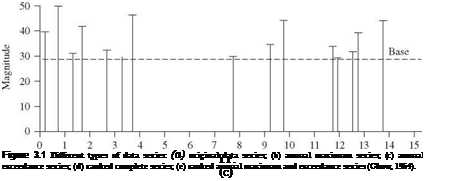
3. A partial-duration series consists of all data above or below a base value. For example, one might consider only floods in a river with a magnitude greater than 1,000 m3/s. When the base value is selected so that the number of events included in the data series equals the number of years of record, the resulting series is called an annual exceedance series. This series contains the n largest or n smallest values in n years of record.

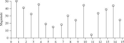
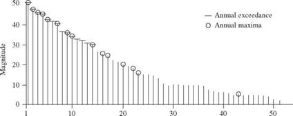
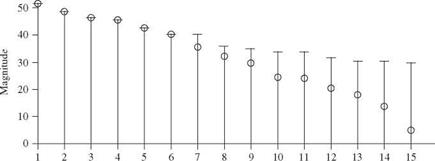
The selection of geophysical data series is illustrated in Fig. 3.1. Figure 3.1a represents the original data; the length of each line indicates the magnitude of the event. Figure 3.16 shows an annual maximum series with the largest data value in each year being retained for analysis. Figure 3.1c shows the data values that would be included in an annual exceedance series. Since there are 15 years of record, the 15 largest data values are retained. Figure 3.1d and e illustrate for comparison the rank in descending order of the magnitude of the events in each of the two series. As shown in Fig. 3.1d and e the annual maximum series and the annual exceedance series form different probability distributions, but when used to estimate extreme floods with return periods of 10 years or more, the differences between the results from the two series are minimal, and the annual maximum series is the one used most commonly. Thus this chapter focuses on the annual maximum series in the following discussion and examples.

Another issue related to the selection of the data series for frequency anal­ysis is the adequacy of the record length. Benson (1952) generated randomly

Types of Geophysical Data Series

Yr.


(a)


Types of Geophysical Data Series

Yr.


(b)


Types of Geophysical Data Series

Types of Geophysical Data Series

Rank

(d)

Types of Geophysical Data Series

Rank

(e)

Figure 3.1 (Continued) selected values from known probability distributions and determined the record length necessary to estimate various probability events with acceptable error levels of 10 and 25 percent. Benson’s results are listed in Table 3.1. Linsley et al. (1982, p. 358) reported that similar simulation-based studies at Stanford University found that 80 percent of the estimates of the 100-year flood based on 20 years of record were too high and that 45 percent of the overestimates

TABLE 3.1 Number of Years of Record Needed to Obtain Estimates of Specified Design Probability Events with Acceptable Errors of 10 and 25 Percent

Design probability

Return period (years)

10% error (years)

25% error (years)

0.1

10

90

18

0.02

50

110

39

0.01

100

115

48

SOURCE: After Benson (1952).

exceeded 30 percent. The U. S. Water Resources Council (1967) recommended that at least 10 years of data should be available before a frequency analysis can be done. However, the results described in this section indicate that if a frequency analysis is done using 10 years of record, a high degree of uncertainty can be expected in the estimate of high-return-period events.

The final issue with respect to the data series used for frequency analysis is related to the problem of data homogeneity. For low-magnitude floods, peak stage is recorded at the gauge, and the discharge is determined from a rating curve established by current meter measurements of flows including similar – magnitude floods. In this case, the standard error of the measurement usually is less than 10 percent of the estimated discharge. For high-magnitude floods, peak stage often is inferred from high-water marks, and the discharge is computed by indirect means. For indirectly determined discharges, the standard error probably is several times larger, on the order of 16 to 30 percent (Potter and Walker, 1981). This is known as the discontinuous measurement error (DME) problem. Potter and Walker (1981) demonstrated that, as a result of DME, the probability distribution of measured floods can be greatly distorted with respect to the parent population. This further contributes to the uncertainty in flood frequency analysis.

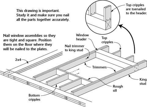
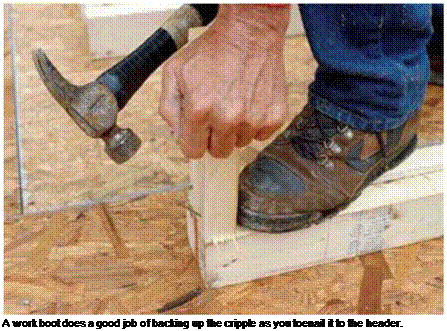
NAILING TOGETHER THE WINDOW FRAME ASSEMBLIES

NAILING TOGETHER THE WINDOW FRAME ASSEMBLIES

Dull tips are IIP useful! When you need to drive a nail near the end of a board, first blunt the tip of the nail. This helps prevent splitting the wood.


NAILING TOGETHER THE WINDOW FRAME ASSEMBLIES

Подпись: iiiiiiiiiiiiiiiiiiiiiiiiiiiiiiiiiiiiiiiiiiiiiiiiiiiiiiiiiiiiiiiiiiiiiiiiii

When you come to a door or window open­ing, just continue the stud layout, marking cripple locations on the headers and the rough sills. Lay out all exterior walls and then begin on the interior walls. The layout of interior walls is not as critical as that of exterior walls, because most drywall hangers use long sheets of drywall, which often run from corner to corner. Just put the stick in a corner against a through wall and start marking. Make sure you put the stud mark­ings on the same side of the plates as the header markings. When you encounter rough plumbing, don’t put a stud next to a pipe. Give the plumbers room to finish their work. Each intersecting wall automatically has a stud on each end, so there’s no need to mark those locations.

Old codes required that a stud be placed under every break in the top plate. Here in the West, this hasn’t been a requirement for nearly 40 years, but check with your local building inspector. My guess is that few, if any, areas in the country still require it. As long as you have
a double top plate, locating a stud under a plate break adds little to the structural integrity of the frame.

Because of the sheer number of marks re­quired on walls, it’s a good idea to walk through every “room” after you have finished marking all the plates. Visually check whether all of the wall plates, headers, rough sills, corners, and channels are properly marked. The time you take to inspect your work now can save you much more time later. It takes a lot longer to tear out studs and frame a door that was missed during layout than it does to take a leisurely but focused stroll through the house to make sure everything is in order.

STEP 5 BUILD THE WALLS

In addition to being a carpenter for the past 50 years, I’ve also been a gardener my entire life, and I see a lot of similarities between framing and gardening. If you take the time to prepare

Подпись:Подпись: Door and window assemblies are nailed together and ready to be installed between the top and bottom wall plates. [Photo © Larry Haun] the ground, add lots of compost, plant good seeds, mulch well, and nurture young plants, you can’t help but grow outstanding vegetables. The situation is similar when you’re framing walls. If you take the time to lay out, cut, and correctly position every part of every wall, then the actual framing will go smoothly and you’ll produce a quality building.
A Habitat volunteer once said to me, “Now the fun starts,” as we began to nail together all the wall pieces. I guess everything in life is relative. If you have to stand out in the blazing sun building walls day in and day out, the joy of framing does eventually wear off. On the other hand, when working as a team, a group of people building walls will see a lot of progress in one day, and that is satisfying.

Before I start building walls, I always begin by cleaning up the work area. Some scrap will have been generated as you cut the parts for the walls and there’s no need to leave it lying around for someone to trip over.

WATER TABLE

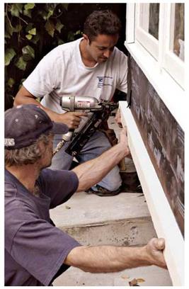
The water table is horizontal trim running around the base of a building below the siding, and not all houses have it. Depending mostly on regional preferences, the water table takes sever­al forms. In the West, it typically looks like win­dowsill ears (the parts that stick out) and is often used to separate different types of siding materi­als, such as shiplap siding from wood shingles above. This strip-like water table usually runs continuously around the building and is mitered at the corners. It often has a rabbeted heel, which fits over the top of the wood siding below, and a

image276

Water-table trim often finishes off the bottom of a wall and provides a level base for the first course of siding.

To forestall rot, cap the water table with metal or vinyl flashing before installing the siding.

Подпись: Trim on older buildings is rarely level or parallel. Thus new trim may look better if it's installed slightly out of level, so that it aligns visually with what's already there. For example, when stretching a chalkline to indicate the bottom of the water table, start level; then raise or lower the line till it looks right in relation to nearby windowsills and the like. Once the chalkline looks more or less parallel to existing trim, snap it on the building paper, and extend it to corner boards.Подпись: llll

beveled top, which is overlain with shingles or clapboards.

In the East, water tables are also called splashboards; they usually are 1-in. boards 8 in. to 12 in. wide and may be capped to shed water. Splashboards are most common in wet regions, where roof runoff often splashes back along the base of a house. (Some primal carpenter may have reasoned it would be easier to replace a sin­gle rotted board than to disturb several courses of siding or that a thicker board would simply last longer.)

Whatever shape of water table you prefer, flash its top with a metal drip-edge that extends at least 12 in. beyond the face of the board. The section where corner boards sit atop the water board is especially rot prone. Prime and paint the boards thoroughly.

CORNER BOARDS

Corner boards are usually 1-in. boards butted together. Siding is then butted against them, making an attractive and weathertight corner.

Not all buildings have horizontal trim below the bottom of the siding. For example, the first (bottom) course of shingles is often doubled and
overhangs the sheathing slightly. In that case, run corner boards 2 in. to 3 in. below the bottom edge of the sheathing; then, after you nail up the first course of shingles, trim the corner board ends level to the shingles’ butts. If the house has a water table or splashboard, measure from its top edge up to the underside of the soffit to deter­mine the length of the corner boards.

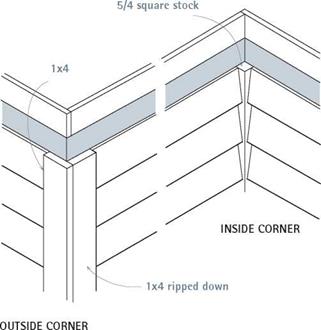
If you’re installing shingles, whose overlap­ping courses have a higher profile than clap­boards, use 5/4 corner boards, which are full 1 in. thick. To give the illusion that corner boards are the same width at each side, rip down the overlapped board by the thickness of the stock. And for a crisp, straight corner, preassemble corner boards before installing them, as explained earlier.

Occasionally, corner boards are nailed over sid­ing. This can be a problem because nails driven through the trim are likely to split the thinner siding. Besides, corner boards can’t seal well if nailed over an irregular surface. This method was commonly used on Victorian homes with flat, shiplap siding. Careful nailing and liberal doses of caulk will help ensure a weathertight seal. To minimize splits, predrill the board nails.

1

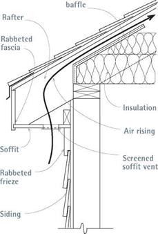
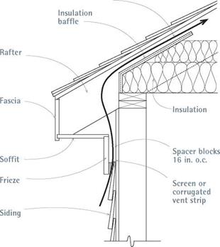
Boxed Eave: Detail 1

Boxed Eave: Detail 2

: 1

1 :1

1

Air rising

image278


Insulation

image277


A strip of continuous screen in the soffit allows you can create ventilation channels behind the frieze by

air to circulate into the attic. The rabbeted frieze spacing it out 3/4 in., using blocks spaced every 16 in. on center.

conceals and protects the top of the siding. This also conceals the top of the siding.

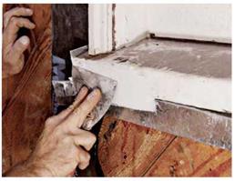
EPOXY REPAIR


Corners


image280

After wire brushing away loose material, inject liquid consolidant into the wood till it becomes saturated. After allowing the consolidant to set, apply the paste-like filler to build up the damaged area.


image281

Use a taping knife to compress and smooth the filler. The galvanized metal tacked to the sill keeps the filler in place until it dries and doubles as a screed strip to which you can level the filler (see the text for more details).


Butt siding to the corner boards to avoid complex miter cuts. In outside corners, rip down the overlapped board by the thickness of the stock, and both boards will look equally wide.


image279

Подпись: If trim paint is a different color than the siding, paint the trim edges—especially hard- to-reach eaves and rake trim— before installing the siding. Using a minimal number of staples, tack staple a 4-in.-wide strip of plastic to the painted trim edges; then install and paint the siding. Finally, rip the plastic out, and—voila—perfect edges! Even if you forego the plastic and need to touch up trim edges, you'll save tons of time. 1111

The corner boards described thus far cover outside corners. Inside corners aren’t as exposed to weather, so wide boards aren’t necessary. Instead, nail 1-in. by 1-in. strips (or 114-in. by 114-in. strips) to the inside corners, and butt the siding to that. That’s much faster than cutting compound miters in the clapboards or inter­weaving shingles.

Densities Too Low

Myths about high-density housing abound. It is widely believed, for example, that higher population densities necessarily increase congestion and strain infrastructures. This just simply is not the case. The congestion myth and the fear it inspires stem largely from some very real conditions that exist in our everyday world. Wherever a design does not accommodate for the number of people and the type of activities that occupy it, there will be overcrowding. But, just as with a house, the solution is not necessarily more space; it is usu­ally better design.

The goal of design is the same for neighborhoods as it is for houses. Good community design has to meet our needs without far exceeding them. The suburbs fail on both these counts. People require open space; while the ‘burbs do offer it on an excessive scale, the space is seldom useful. We inhabit outdoor space in specific ways, and the gaps left over between build­ings and roads are seldom sufficient to accommodate our specific activities. The assumption that arbitrary swatches of pavement and bluegrass can well serve our outdoor requirements is mistaken. Such uninspired places rarely get used because they provide no sense of place or purpose.

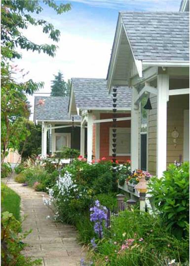
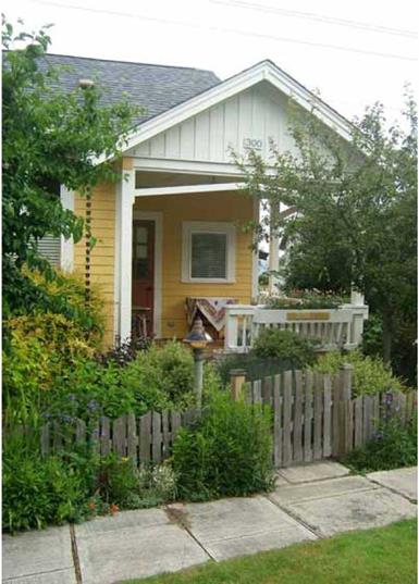
High-density development is particularly conducive to comfortable outdoor environments. Providing enclosure without confinement is key. Consider ar­chitect Ross Chapin’s Third Street Cottages in Langley, Washington. It is a "pocket neighborhood,” comprised of eight, 975-square foot cottages and a shared workshop, all encircling a community garden. Eleven parking spaces have been provided out back. A footpath connects the houses and frames the common garden at center. A strong sense of enclosure is provided by the surrounding cottages and reinforced by a low, split-cedar fence separating the tiny private garden of each home from the shared one. This idyllic setting seems to hug without squeezing too hard. It is twice as dense as zoning nor­mally allows for the area, and yet, there is not a trace of crowding.

Elfreth’s Alley in Philadelphia offers another example of congestion-free, high-density development. The community was built before zoning laws were enacted. Elfreth’s Alley was, in fact, established over 300 years ago and has been inhabited ever since. At about 20 feet wide with 25-foot-tall houses on either side, this development falls well within the parameters of the recom­mended building height-to-road width ratio. It is host to one-way automobile traffic, the residents of its 38 row houses, and thousands of tourists enjoy­ing the all-too-rare experience of a place designed for people rather than cars. On this narrow, cobbled road flanked by brick, stone and foliage, it is easy to feel at home if only because it all makes perfect sense. There are no strange codes at work and no inexplicable abyss. It is not crowded, and it is not sparse. Like Third Street Cottages, Elfreth’s Alley is exactly what it needs to be and nothing more. In each of these places, thoughtful design with particular attention to proportion and scale has been employed to make an environment where serenity and vitality coexist. Each should be a model for those designers and lawmakers who have a hand in our future.

image34

Third Street Cottages on Whidbey Is.

image35

Third Street Cottages on Whidbey Is.

image36

Elfreth’s Ally in Philadelphia

Stage 6: Selecting an Aggregate Mix

An optimum variant should be selected out of the three defined trial design grada­tion curves. The selection criteria of the optimal gradation curve should consist of the smallest amount of coarse aggregate combined with the following two conditions at the same time:

• VCAMIX is lower than VCAdrc or the VCA ratio (VCAmix/VCAdrc) is less than 1.0.

• VMA is higher than 17.0% (v/v) (usually minimum values of 17.5-18.0%).

If the VCAMIX is higher than the VCAdrc, the creation of a skeleton is not guaran­teed. It can be changed by increasing the amount of particles bigger than the BP sieve—that is, increasing the amount of aggregates retained on the BP sieve should increase the VCAdrc. So sometimes additional trial gradations must be analyzed before finding an optimal solution.

Using this method, only one mix is eventually left. The monitoring of the skeleton and aggregate structure is behind us. Now it is time for the binder.

CLIENT-CONSULTANT RELATIONSHIP

State departments of transportation, bridge and turnpike authorities, and other agencies often require the services of a consulting engineering firm. This may be because the agency chooses not to maintain an engineering staff of its own, because its workload is greater than its staff can handle, or because expertise in special kinds of bridges is needed. Consultants can fill these needs.

Where only routine types of bridges are involved and the agency has an engineer­ing staff, the best that a consultant can be expected to do, usually, is only as good a job as the agency’s engineers can do. The agency’s staff may include veteran engi­neers who have become extremely proficient in design of routine and not so routine bridges, and who also know exactly how to prepare plans in the proper format and sheet sequence preferred by the agency, as well as how to use exact pay item

descriptions and to refer to pertinent proposal notes and special provisions. A consul­tant, in this instance, is like a temporary employee who knows the basics but needs to be trained in local procedures.

When a consultant serves a client for many years, however, that consultant can become as proficient as the agency’s staff. Long-term contracts for continuing or on-call services eliminate the need to train a new consultant. However, they can be seen as showing favoritism in an environment where other consultants expect an opportunity to compete for contracts. For this reason, and because a long-term contract may allow a consultant to become complacent, the client may limit the term of the contract and, upon expiration, issue a request for proposals (RFP) to perform the services. The original con­tract holder may or may not be eligible to respond to this RFP, at the agency’s discretion.

In other instances, agencies may hire consultants as program managers. In these cases, the consultant manages designated design and construction contracts for the agency, providing administration, technical review, and construction inspection services.

Consultant’s Responsibilities. To serve the client in a professional and efficient manner, the consultant should

• Deliver the product promised in the contract scope of services

• Deliver the product on time

• Conform to accepted codes and standards

• Develop economical designs

• Use time-tested materials, avoiding purely experimental materials and systems

• Confirm in writing to the client any verbal understandings

• Keep the client informed of project status

• Avoid issues that could involve the client in litigation

• Not make statements to the public or to the media without the client’s knowledge and authorization

Client’s Responsibilities. Just as the consultant has a responsibility to the client, the client has a responsibility to the consultant. Responsibilities include

• Executing a contract with the consultant that includes adequate hours to perform the work, recognizing any unique requirements, and not applying standard allowances for nonstandard work.

• Performing reviews in a timely manner.

• Performing reviews either concurrently or sequentially, but not expecting the consultant to make changes required by one branch of the client’s office only to be subsequently countermanded by another branch. In other words, the client should transmit con­solidated review comments.

• Not interrupting the work unless absolutely necessary.

• Paying invoices in a timely manner. Contracts with subconsultants often stipulate that the subconsultant’s invoices will not be paid until payment is received from the prime consultant’s client, so a delay in payment from the client results in delay of payment to the subconsultant.

• Being frank with the consultant about any dissatisfaction the client may have with the consultant’s performance so that corrective action can be taken immediately.

If the client and consultant meet their respective responsibilities, the relationship will be a partnership that benefits both parties.