STACK VENTS, VENT STACKS, AND RELIEF VENTS

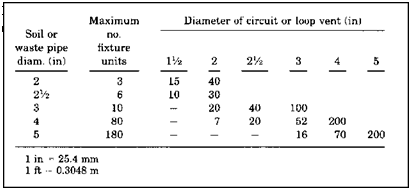
Stack vents, vent stacks, and relief vents require more information for sizing. Specifically, you must know the fixture-unit load on a drain before you can determine vent sizing and developed lengths. Once you have calculated the fixture units, a sizing table can be used to give you your sizing information. The table shown in Figure 5.31 is the type of table that would be used to de­fine the requirements of stack vents, vent stacks, and relief vents. Like the other tables, this one is self-explanatory. To prove this, size the diameter and maximum length of a vent stack that will serve 20 fixture units with a drain di­ameter of two inches. Assume that you want your vent pipe to have a diame­ter of one and a half inches. The answer is that your vent size is okay, as long as you don’t extend it more than 50 feet. If you need more distance, increase the size of the vent to a 2-inch diameter and feel free to run the vent up to 150 feet. The table is easy to use, but you must be able to calculate the load of fixture units. How will you do that? I’ll show you.
Подпись:Most codebooks will provide you with some form or a chart or table that identifies fixture-units for drainage piping. A table like the one in Figure 5.32 is quite helpful. By looking at such a table, you can quickly determine the load, in terms of fixture units, that an individual fixture puts on a drain. For example, a bidet carries a fixture-unit rat­ing of 2. A drinking fountain is rated for one half of a fixture unit. A residential wa­ter closet is worth 4 fixture units. By using this type of table to assign fixture-unit rat­ings to all fixtures being served by a drain, you can then arrive at a number to use with the vent-sizing table. For fixtures that are not listed, you can use a generic table, like the one in Figure 5.33, to assign ratings for fixture units.

‘О

оо


Подпись: PLUMBER’S AND PIPE FITTER’S CALCULATIONS MANUAL
STACK VENTS, VENT STACKS, AND RELIEF VENTS

FIGURE 5.30 ■ Individual and branch vent sizing table for horizontal soil and waste branches. [Courtesy of Standard Plumbing Code)

Size of soil or

Diameter of vent required (in)

(in)

connected

lVi

1У2

2

2У2

3

4

5

6

8

V/i

2

30

1V5>

8

50

150

1У2

10

30

100

2

12

30

75

200

2

20

26

50

150

2’/2

42

30

100

300

3

10

30

100

200

600

3

30

60

200

500

3

60

50

80

400

4

100

35

100

260

1000

4

200

30

90

250

900

4

500

20

70

180

700

5

200

35

80

350

1000

5

500

30

70

300

900

5

1100

20

50

200

700

6

350

_

_

25

50

200

400

1300

6

620

15

30

125

300

1100

6

960

—•

24

100

250

1000

6

1900

20

70

200

700

8

600

50

150

500

1300

8

1400

_

_

_

__

_

40

100

400

1200

8

2200

30

80

350

1100

8

3600

25

60

250

800

10

1000

75

125

1000

10

2500

50

100

500

10

3800

_

_

_

30

80

350

10

5600

25

60

250

1 in = 25.4 mm 1 ft = 0.3048 m

Подпись: VENT SYSYEM CALCULATIONSFIGURE 5.31 ■ Maximum length of stack vents, vent stacks, and relief vents. (Courtesy of Standard Plumbing Code)

‘O

SO


Fixture type

Fixture-unit value as load factors

Minimum size of trap (in)

Bathroom group consisting of water closet, lavatory, and bathtub or shower

6

Bathtub1 (with or without overhead shower) or whirlpool attachments

2

lVz

Bidet

2

Nominal 1У2

Combination sink and tray

3

T/2

Combination sink and tray with food disposal unit

4

Separate traps ІУ2

Dental unit or cuspidor

1

1У4

Dental lavatory

1

1У4

Drinking fountain

‘/2

1

Dishwashing machine2 domestic.

2

1У2

Floor drains5

1

2

Kitchen sink, domestic

2

1У2

Kitchen sink, domestic with food waste grinder and/or dishwasher

3

1У2

Lavatory4

1

Small P. O. l’/4

Lavatory4

2

Large P. O. 1У2

Lavatory, barber, beauty parlor

2

ІУ2

Lavatory, surgeon’s

2

ІУ2

FIGURE 5.32 ■ Fixture units per fixture or group. (Courtesy of Standard Plumbing Code)

Stage 5: Testing an Aggregate Mix and an Asphalt Mixture

So far, we have carried out a series of tests. Let us sum up all the data at our disposal as follows:

• Air voids in the compacted coarse aggregate VCAdrc

• Initial (or adjusted if needed) content of binder

We have also made a series of compacted SMA samples. Now it is time to determine the following features for them:

• Bulk density of the compacted SMA sample

• Maximum density of the SMA mix

• Content of air voids in the compacted SMA samples (Va)

• Content of VMA

• Content of air voids in the coarse aggregate of the aggregate mix

(VCAMIX)

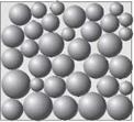
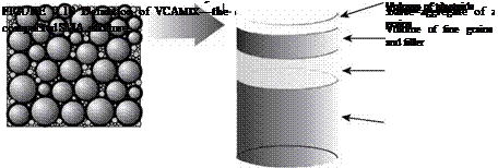
Among these features, only VCAMIX is a new one. It is vitally important to under­stand the differences between the terms VCAdrc, VMA, and VCAMIX. All of them describe voids in an aggregate mix or one portion of the aggregate mix. Figures 7.9 through 7.11 show their graphic representations. The following is a brief description of the three:

• VCAdrc—content of air voids in the compacted coarse aggregate (coarse aggregate portion of the total aggregate mix, retained on the BP sieve)

image65image66image67vcadrc Volume of air voids in coarse aggregate

Volume of coarse grains

image68,image69,image70
FIGURE 7.9 Definition of VCADrc—the content of air voids in a compacted coarse aggregate.

image71,image72,image73,image74

VCAMIX—content of air voids in the coarse aggregate of a compacted SMA mixture—that is, the volume of everything but the coarse aggregate in the SMA mixture, or the volume of binder, filler, fine aggregate, and air voids)

• VMA—content of air voids in an SMA aggregate mix, equal to the sum of air void volume in a compacted SMA plus the volume of effective binder, excluding filler and fine aggregate

GENERAL PREPARATION

Exterior trim can be applied in many different ways, depending on the design of the house and the type of siding. For wood shingles or clap­boards, use trim boards that are thicker than the siding, and apply trim to the sheathing before putting up the siding. For flat shiplap and board- and-batten sidings, apply trim boards over the siding. In general, try to use the same materials and installation methods that were used on the house originally.

Solid-wood exterior trim should be a rot – resistant species such as redwood, cedar, or hard pine and sufficiently dry to avoid shrinkage, cup­ping, and checking. For those reasons, avoid sugar pine, knotty pine, hemlock, fir, and the like. If you’ll be painting the trim, you may find it cost effective to use finger-jointed trim stock fabricated from shorter lengths of high-grade wood. Such stock is widely available and can be durable if you keep it sealed with paint. For best results, specify vertical-grain heartwood grade because it

Eaves Trim___________

Rake trim

image272

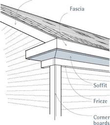
Fascia, soffit, and frieze boards are collectively called the eaves trim.

image273

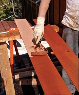
Prime all faces and edges of exterior trim and siding, including the back faces. Back priming is especially important because moisture trapped between back faces and sheathing can lead to paint or sealer failure, cupping or—in extreme cases—structural rot. After cutting trim or siding, be sure to prime the cut edges as well.

resists decay, holds paint well, and is the most stable dimensionally. Caution: If this trim is allowed to absorb moisture, its finger joints may separate.

BACK-PRIMING AND PAINTING

Apply primer to all faces and edges of exterior wood (and engineered wood) siding and trim, including the back faces. Back-priming is critically important because wood will cup (edges warping up) when the sun dries out the exposed front face, while the back unexposed face retains mois­ture. The greater the moisture differential between front and back faces, the more likely the cupping.

While cutting trim or siding, keep a can of primer and a cheap brush nearby to seal the ends after every cut; unprimed end grain can absorb a lot of moisture. (It’s especially easy to forget to prime cut edges when you’re using preprimed trim.) Ideally, apply at least two top coats of acrylic latex paint after priming to seal trim and siding. If you want stained or clear-finished trim or siding, use cedar or heart redwood.

ATTACHING TRIM

As a rule, for best attachment, secure exterior trim to framing. In those rare instances where you have only sheathing to nail to, angle the nail so that it will be less likely to pull out.

Choosing attachers. Pick a nail meant for exte­riors. If you’ll be using a transparent finish, mak­ing nail heads visible, stainless-steel nails are the premier choice; though expensive, they won’t

rust. Aluminum nails won’t stain but are some­what more brittle and more likely to bend. Galvanized nails are the most popular because they’re economical, stain minimally, and grip well. Many nail types (including stainless) also come in colors matched to different wood types—cedar, redwood, and so on. Ring-shank nails hold best.

For stained exteriors, some contractors prefer galvanized finish or casing nails because their heads are smaller and less visible. Box nails are a good compromise. Their larger heads hold better than finish nails, yet their shanks are smaller than those of common nails, making box nails less likely to split wood. There are also “splitless” siding nails that come with preblunted points to minimize splits. (The blunt point smashes through wood fibers, rather than wedging them apart.)

Where trim is exposed—say, at cap trim atop a half wall—and you want maximum grip, use stainless-steel trim-head screws instead of nails.

drive nails quickly and accurately, reducing splits and eliminating errant hammer blows that mar trim. After setting the trim with finish nails, you can always can go back and hand nail with headed nails to secure the trim further. Or you can use headed siding nails in the nailer.

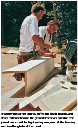
Подпись: Engineered Trim: A PrimerПодпись: Pneumatic nailers. Most pros use pneumatic nailers to attach exterior trim. Using a finish nailer with galvanized nails allows you to tack up trim exactly where you want it. Anyone who has spent time trying to simultaneously hold and nail a 16-ft. corner board in place while balancing on a ladder will appreciate this tool. Nailers alsoПодпись: Preassemble corner boards, soffit-and-fascia boards, and other exterior trim on the ground whenever possible. The joined pieces will be tight and square, even if the framing and sheathing behind them isn't.

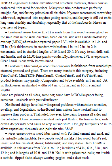
Подпись: Just as engineered lumber revolutionized structural materials, there's now an engineered trim rated for exteriors. Many such trim products are perfectly straight, flat, and factory primed on all six sides. If you're accustomed to working with wood, engineered trim requires getting used to, and the jury is still out on its long-term stability and durability, especially that of the hardboards. Here's an overview of types: ► Laminated veneer lumber (LVL) is made from thin wood veneers glued so the grain runs in the same direction, faced on one side with a medium-density overlay (MDO) of resin-impregnated paper. LVL trim is available in 1-in. and Ш-in. (5/4) thicknesses; in standard widths from 4 in. to 12 in., in 2-in. increments; and in standard lengths of 16 ft. and 20 ft. It's easy to cut, drill, nail, and handle, and its MDO face paints wonderfully. However, LVL is expensive. Clear Lam® is one well- known brand. ► Hardboard, fiberboard, or wood-fiber composite is fashioned from wood chips steamed, pressed, and glued. There are many brands in this category, including TrimCraft®, MiraTEC®, PrimeTrim®, ChoiceTrim®, and ProTrim®, and product features vary greatly. Composites tend to be available in 1-in. and UA-in. thicknesses, in standard widths of 4 in. to 12 in., and in 16-ft. standard lengths. Some are primed on all sides, some not; some have MDO-like paper facing, some not—so check with your distributor. Hardboard sidings have had widespread problems with moisture retention, swelling, and degradation, so hardboard-trim makers have worked hard to improve their products. That noted, however, take pains to prime all sides and the cut edges. Drive corrosion-resistant nails just flush to the trim surface; nails driven deeper may need caulk to keep out moisture. Last, gap butt joints ‘A in. to allow expansion; then caulk and paint the trim ASAP. ► Fiber-cement trim is wood fiber mixed with Portland cement and sand, and it's virtually indestructible. Few people would mistake it for wood, but it's rot, insect, and fire resistant; strong; lightweight; and very stable. HardiTrim® is available in thicknesses from Ум in. to 1 in.; in widths of 4 in., 6 in., 8 in., and 12 in.; and in lengths of 10 ft. and 12 ft. Nail it with galvanized nails; cut it with a carbide- tipped blade, always wearing goggles and a dust mask.

Nailing schedules. To face-nail nominal 1-in. trim (actual thickness, % in.), use 8d box nails spaced every 16 in. Nail both edges of the trim board to prevent cupping, placing nails no closer than h in. to the edge. If the trim goes over sid­ing, say, at corners, use 8d to 10d box nails. To draw board edges to each other, use 6d nails spaced every 12 in., and drive them in a slight angle. If you’ll be painting the trim, also caulk this joint or glue it using an exterior urethane glue, such as Gorilla Glue®.

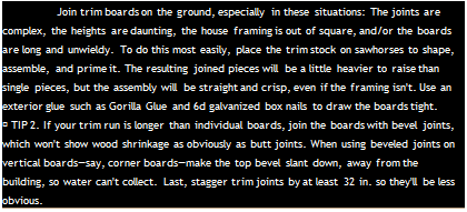
image275"Подпись: EXTERIORПодпись: Join trim boards on the ground, especially in these situations: The joints are complex, the heights are daunting, the house framing is out of square, and/or the boards are long and unwieldy. To do this most easily, place the trim stock on sawhorses to shape, assemble, and prime it. The resulting joined pieces will be a little heavier to raise than single pieces, but the assembly will be straight and crisp, even if the framing isn't. Use an exterior glue such as Gorilla Glue and 6d galvanized box nails to draw the boards tight. ► TIP 2. If your trim run is longer than individual boards, join the boards with bevel joints, which won't show wood shrinkage as obviously as butt joints. When using beveled joints on vertical boards—say, corner boards—make the top bevel slant down, away from the building, so water can't collect. Last, stagger trim joints by at least 32 in. so they'll be less obvious. rior Trim tips

About nail heads. Taking the time to line up nail heads makes the job look neater. For example, when nailing up jamb casing, use a combination square to align nail pairs. If you’re putting up a long piece of trim that runs perpendicular to studs, snap chalklines onto the building paper beforehand so that you’ll know stud positions for nailing. If the trim will be painted, take the time to set the nail heads slightly below the surface, using a flathead punch. Then use exterior wood filler to fill the holes. If you don’t set the heads slightly, they may later protrude as the wood shrinks, compromising the paint membrane and admitting water. On larger jobs, carpenters are usually expected to set nail heads. Painters fill and paint them.

EAVES TRIM

Because eaves trim is often complex and can impact framing, roofing, ventilation, and the house’s aesthetic integrity, draw a cross-section of it as early as possible.

There is no single correct way to construct the eaves, but the boxed eaves on the facing page are a good place to start. First, a fascia board that overhangs a soffit by % in. to in. enables you to hide rafter irregularities—rafters are rarely per­fectly straight or cut equally long. Second, that overhang accommodates a rabbeted fascia-soffit joint, which protects the outer soffit edge, even if the wood shrinks slightly. Third, if you rabbet out the back edge of a frieze board or build it out using blocks, the frieze will conceal the top edge of the siding. A built-out frieze also creates an inconspicuous space to install an eave vent.

Ventilation channels at eaves allow air to flow up under the roof and exit at ridge or gable-end vents. This airflow is beneficial because it lowers
attic temperatures and helps remove excess mois­ture from the house, thus mitigating mold, ice dams, and a host of other problems. To keep insects out, soffits need screening. In a wide sof­fit, there’s plenty of room for screened vents in the middle. In a narrower soffit, you may need to leave a M-inch space at the front of the soffit or at its back, hidden behind a built-out frieze board.

If the house has exposed rafter tails rather than soffits, cut down the blocking between rafters so air can flow over the top. Again, staple fine mesh screen or corrugated vent strips behind ventilation passages to keep insects out.

Techniaues BUILDING CORNERS AND CHANNELS

LIKE HEADERS, OUTSIDE corners and channels can be built in a number of different ways, and pref­erences tend to be regional. The most common con­structions are shown in the illustration below. A two-stud outside corner works well in most cases, but if you are planning to install clapboard or fiber-cement siding directly to the studs (with no exterior sheathing), you’ll need more backing at the outside corners. A blocked-up corner provides more backing and makes good use of 2x offcuts.

In addition, all of these outside corner configura­tions provide backing on the inside of the wall for drywall or other wallboard.

Channels (sometimes called tees) are most easily made w;th a flat stud or blocks nailed between two regular studs. I place a crowned or knot-filled stud between two good studs. In some parts of the coun­try, framers build ladder-type channels to provide backing at intersecting walls. Building ladder back­ing doesn’t save a lot on materials, but it does allow more insulation to be inserted at those spots.

Both corners and channels are nailed together with one 16d nail every 2 ft. o. c. When nailing channels to the top and bottom plates, make sure that the flat stud is oriented correctly to provide backing for an intersecting wall. It’s not difficult to put in a channel upside-down.

BUILDING OUTSIDE CORNERS AND CHANNELS


Intersecting wall


Iwo*stud corner


Blocked-up corner


Ladder-backing channel


Three-stud channel


An outside corner can be made with two studs and three short blocks.


A channel can be made from three studs or from two studs and three short, flat blocks nailed between them.


A channel made with short 2x$ nailed between the studs allows the area to be well insulated.


Techniaues BUILDING CORNERS AND CHANNELS

Шcorner saves a 2x stud fallows for more insulation «the wall.

Techniaues BUILDING CORNERS AND CHANNELS

Techniaues BUILDING CORNERS AND CHANNELS

MAKE A CHANNEL.

A pneumatic nailer makes quick work of this assembly, which consists of two studs separated by 2×4 blocking.

Подпись: 'XV ГTechniaues BUILDING CORNERS AND CHANNELS

NAIL ON THE TOP PLATE. After separating the top plate from the bottom plate (visible in the background), the top plate can be nailed to the studs, channels, and window and door assemblies. Drive a pair of 16d nails into each stud.

from the bottom plate, removing the 8d tack nails as you go. Leave the bottom p ate tacked to the floor for now. Nail the top plate first, using the bottom plate to keep the studs aligned. Move the top plate straight up to the upper ends of the studs. Don’t turn a top plate end for end as you move it into position or you’ll have a real mess. The exterior walls am be framed over the interior walls rather than fiat on the deck or slab (see the pholo at left). This is okay. The most important element in wall framing is to keep the frame reasonably straight and square on the floor. This is not difficult to do. Take vour time until you get it right.

Begin nailing studs to the plate at an out­side comer, making it flush with the edge. Drive a pair of 16d nails through the plate into each stud. You will find that consistently working either from left to right or from right to left has a natural feel. Over time, von will develop a rhythm to nailing studs that involves not just your hands and arms but your entire bodv.

If you are using a pneumatic nailer, always drive the bottom nail first. Then remove your
hand from the stud and drive the top nail. If you keep your hand in place while driving the top naif sooner or later you will miss and drive a nail into your hand. Unfortunately» I

learned this the hard wav.

/

W hen you come to a door or window opening, be especially careful to nail each king stud on the“X” mark next to the header loca­tion. Once nil the wall, king, and top cripple studs arc nailed to the top plate, pull up the bottom plate and begin nailing it n place, always paying attention to your layout marks. Repeat the process. Nail all wall members to the bottom plate just like you did with the top plate.

I always nail the blocks for a recessed, or in-wall, medicine cabinet while the wall is flat on the floor. At the “MC marking, hook your tape on the bottom plate and measure up 4 ft. and 6 ft. on the two studs on each side. Nail a flat block below the 4-ii. marks and above the б-ft. marks. This leaves a clear space of 2 ft., which is the height of a standard recessed medicine cabinet.

D. Chalking Lines Duplication Method

This method is probably the easiest to use. To find the lengths of rafters, you make an actual size drawing of the rafter on the floor and then measure the length.

All the information you need to use this method should be on the plans. First you will need the pitch. (See Method C mentioned previously.) Second is the span, which is the distance from the support on one side of the rafter to the support on the other side. Third is the width of the rafter, the length of the roof overhang, and the size of the exterior wall.

Steps (shown in Line Chalking Sequence illustration):

1. Chalk a straight line longer than the length of your rafter, which would represent the bottom of the ceiling joist if there were a ceiling joist.

2. Chalk two lines perpendicular to the first line to represent the exterior wall.

3. From the point where your inside exterior wall line crosses the ceiling joist line, measure out and up according to your pitch xp2. For this example let your pitch equal 6г2. Therefore, for every 12” you measure out, you measure 6” up. The longer the distance out, the greater your accuracy. Make sure that the line up is exactly perpendicular or square. You can use surrounding walls that are square to measure from or measure a 3-4-5 triangle.

5. Measure the distance for the span along the ceiling joists line, then make a perpendicular line up and mark the ridge board.

6. Measure the distance of the roof overhang and draw in the fascia board.

With these lines in place, you can measure all the lengths you will need to cut your rafters.

Line Chalking Sequence

4. Chalk a line for the thickness of the rafter.

Roof Production

Rafter Pr°fiies E. Computer Software

Method

Using the methods described on previous page to find the lengths and angles for cutting rafters is not easy, but it is at least organized—and with a calculator that works in feet and inches and that figures the diagonals automatically, the process is straightforward. However, the easiest method is to use the computer. There are software programs currently available that will do all the work for you and produce a sketch of each rafter. Solid Builder is one of these programs.

The illustrations on this page were done in Solid Builder. “Roof Production" identifies the type of roof parts, the quantity, lumber, and strength. “Rafter Profiles" illustrates the individual rafters with the balance of information you will need for cutting the rafters.

The hardest part of producing these computer­generated diagrams is learning the software and then entering the information needed for

each structure in order to generate the diagrams. However, for the architect who has already drawn up the plans, or the builder who is working with computer-generated plans, it is an easy task to produce these rafter profiles. If computer-generated rafter profiles were prepared and attached to plans, it could really make framing roofs a breeze.

BLOCKING IN BATHROOMS AND CLOSETS

Nailed between studs, blocking provides solid backing for items such as towel racks, closet shelves, and safety grab bars. Blocking ensures that the mounting hardware for those devices can be anchored with screws driven into solid wood, so that you don’t have to worry about racks, bars, and shelves pulling loose.

It’s smart to include blocking when marking up wall plates. Cut blocking boards from 2x scraps. As shown in the illustration at right, blocking is installed so that the face of the 2x is flush with the edges of the studs. To help locate blocking, use these standard heights for common bath, kitchen, and storage fixtures:

■ Towel bars: Near the tub and vanity, center blocks 54 in. above the floor.

■ Toilet-paper holder: Near the toilet, center blocks 24 in. above the floor.

■ Toothbrush and soap holder: Above the sink, center blocks 40 in. above the floor.

■ Safety grab bars: Near the toilet and near (or in) the bathtub/ shower, center blocks 36 in. above the floor.

■ Closet shelf and pole: Block 66 in. above the floor; more blocking may be needed if you install wire shelves.

Подпись: WALL-BLOCK HEIGHTS FOR BATHROOM FIXTURES Подпись: All measurements are from the floor to the center of the blocking. Подпись: Many fixtures in a bathroom require solid blocking behind the drywall to ensure safe, secure mounting.Подпись:Linen-closet shelves: First block above the floor at 20 in., then block every 14 in. thereafter for above-floor measure­ments of 34 in., 48 in., 62 in., and 76 in. Don’t forget to block for a shelf or two in the utility room to hold detergent and other laundry items.

Подпись:

and hold door and window frames together.

On the other side of the line, underneath the header, make a long, straight line along both plates to indicate that there will be an open­ing at that location and that no studs should be nailed there.

No matter what the plans indicate, keep interior wall headers at least ІУ2 in. away from corners and channels so you’ll have space on which to nail door and window trim. In hurri­cane and earthquake zones, exterior walls must not have window or door openings less than 4 ft. from an exterior corner, so that these sec­tions of wall can be braced properly.

Above all, mark clearly. These plates will be pulled up and moved during framing. Clear marks improve the odds that all framing mem­bers will be attached accurately.

Use special markings to help other tradespeople

It’s important to remember that the framing must accommodate plumbing, heating, and electrical features. Talk to the subcontractors

BATHROOM STUD AND BACKING LAYOUT

2×6 wall 141/2-in. space for

BLOCKING IN BATHROOMS AND CLOSETS


In addition to regular studs, bathroom walls need special layouts for the tub backing, medicine cabinet, and access to the drain.

Подпись: MAKING A LAYOUT STICK Whether you use a store-bought layout stick or make your own, this tool will save you a lot of time when marking plates in preparation for wall construction. A stick like the one shown here can be used to lay out studs on 16-in. and 24-in. centers. To make your own layout stick, cut a series of 11/2-in.-wide strips from a panel of 3/4-in.-thick plywood. Cut one strip 49У2 in. long and five strips 9У2 in. long. Glue and nail the short pieces to the long piece at right angles and at the spacing shown in the illustration below.The 3-in. legs allow you to mark top and bottom plates at the same time.The 5-in. legs make it easy to mark two plates side by side and to mark headers and rough sills along with the plates. BLOCKING IN BATHROOMS AND CLOSETS

before you even start on the floor. Show them your plans and find out what you can do when it comes time to frame walls so that they can do their work without having to remodel your structure.

You can start by asking the plumber whether there’s anything you can do while laying out the bathroom to make it easier to install the pipes. The plate layout for a typical bathroom is shown in the illustration on p. 91. Code requires a mini­
mum of 31 in. from sidewall to sidewall for a toilet. The wall behind a toilet is usually І2У2 in. from the center of the waste drain. Standard bathtubs are usually 30 in. wide and 60 in. long. If building on a slab, you may need a 12-in. by 12-in. access hole in the wall so the plumber can hook up or repair the tub trap. Measure 15 in. from the wall to the center of the tub trap and make a mark. Then measure 6 in. to each side of the mark (for a 12-in. hole) and strike lines onto the plates. Mark an “X” on the outside of these lines on both plates to show the studs’ positions.

Once a tub/shower unit has been installed, the plumber will nail it in place to a backing stud. Measure 32 in. from the corner and mark both plates with a keel. The stud location falls away from this mark. Toward the inside, mark the lo­cation of a flat stud that will be nailed to the first stud. The flat stud provides backing for the tub.

Plans often show an in-wall medicine cabinet centered over the bathroom sink. The standard rough opening for an in-wall medicine cabinet is 14І/2 in. wide. To accommodate one, measure 71/4 in. in each direction from the center (directly over the sink’s drain pipe) and mark across both plates with a keel, making an “X” on the outside of each line to indicate the studs’ locations. This will give you a 14//2-in.-wide rough opening for the medicine cabinet. Write “MC” on the plates between the two stud locations.

Include blocking requirements when mark­ing up plates. As explained in the sidebar on p. 90, blocking between studs provides solid backing for important items, such as towel bars, built-in shelves, and so on, which will be installed after the interior walls are finished. If you’re building a porch, this is also the time to mark the location of any porch beams (see Chapter 6). Porch beams recess 3 in. inside the walls and re­quire two trimmers underneath to support them.

Mark stud locations last

I don’t know who made the first layout stick for marking stud locations, but I have been using one for almost 50 years. You can either make

Подпись: Stud layout is a quick process when you use a layout stick. Position the layout stick 34 in. beyond a corner on outside walls and mark stud (and cripple) locations every 16 in. or 24 in. o.c.
one (see the sidebar on the facing page) or buy one (see Resources on p. 279). I learned how to do stud layouts with a long tape and a small square, but I think it is faster and easier to use a layout stick.

Take a look at the building plans. Exterior walls generally have studs spaced 16 in. o. c. Interior wall studs may also be spaced 16 in. o. c. but are sometimes 24 in. o. c. When exterior walls are sheathed with plywood or OSB, the studs are spaced to fit these 4-ft. sheets.

BLOCKING IN BATHROOMS AND CLOSETSПодпись: Before we can nail the walls together, other parts (top and bottom plates, the studs, and any openings) must be assembled. Raising walls is hard work, but driving nails can be pretty satisfying, whether you use a good, old-fashioned hammer or a pneumatic nailer.Start the stud layout at one end of a long ex­terior wall. Place the layout stick on the outside edge of the plates, with the first tab 3/4 in. be­yond the end of the wall. This sets up a 16-in.- o. c. or a 24-in.-o. c. layout that will accommodate the 4-ft.-wide sheathing sheets (see the photo above). Mark both sides of the remaining tabs to note the locations of the next three studs. Move the layout stick, line up the end tab with the last mark, and mark again. If you’re nailing a sheet of OSB at the outside corners for bracing, make sure you lay out a stud 4 ft. from each corner in both directions.

A SIZING EXERCISE

Подпись:A SIZING EXERCISE
Let’s do a sizing exercise to illustrate how the tables from a codebook might be used to determine the size of piping needed for various vents. When you set up a vent sys­tem, you must know how far a vent is al­lowed to be from the trap it is serving. If you look at Figure 5.27, you will see the re­quirements for one of the major plumbing codes. The table is easy enough to understand. If you have a fixture drain that has a diameter of 1.5 inches and a trap size of 1.5 inches, with a grade of a quarter of an inch per foot, the trap may be as much as five feet from the vent. With this particular code, the dis­tance would remain the same, even if the trap size was only one and a quarter inches in diameter, so long as the drain remains as a 1.5 inch diameter.

Size of fixture drain (in)

Size of trap (in)

Fall (in/ft)

Max. distance from trap

lVi

1У4

У.

3 ft 6 in

1У2

1У4

У4

5 ft

1У2

1У2

Va

5 ft

2

1У2

Va

8 ft

2

2

Va

6 ft

3

3

Vs

10 ft

4

4

Vs

12 ft

1 in = 25,4 mm 1 ft = 0.3048 m

FIGURE 5.27 ■ Distance of fixture trap from vent. (Courtesy of Standard Plumbing Code)

A SIZING EXERCISEIf the size of the fixture drain was three inches in diameter, with a 3-inch trap, and one-eighth of an inch of fall per foot, the vent could be up to 10 feet from the trap. Obviously, this type of table is easy to understand and to work with.

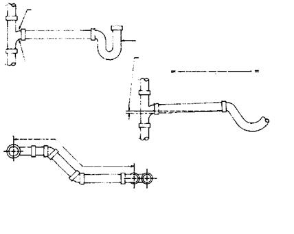
Vent sizing is based on developed length. This is the measured distance of all pipe used in the system. Measurements are taken on a center-to-center basis. You can see in Figure 5.28 how the measurements are assessed. Once you know the developed length of a vent, you can use a sizing chart to de­termine the minimum diameter of the vent pipe. The sizing of a vent or vent system is not difficult. Let me show you how it’s done.

A SIZING EXERCISE A SIZING EXERCISE

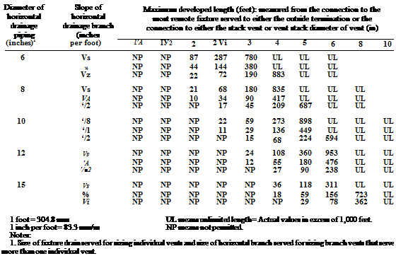
Look at Figure 5.29. This is a chart designed for sizing individual and branch vents serving horizontal soil and waste branches. As you look at the table, you will see two types of abbreviations. The abbreviation shown as NP means "Not Permitted". When you see the abbreviation of UL, it means "Un­limited". Aside from these two clarifications, the table pretty much speaks for itself. Try to find the answer to the question I’m about to give you. Assume that you have a drain that has a 2-inch diameter. The amount of fall on the pipe is set at one quarter of an inch per foot. You want to run a vent with a di­ameter of 1.5 inches. How far can you run the vent in that size? The answer is that there is no limit to the length of the vent run. But, suppose you wanted the vent diameter to be 1.25 inch, how far could it go? A vent of this size

FIGURE 5.28 ■ Distance of fixture trap from vent. (Courtesy of Standard Plumbing Code)

‘чО

O’*


Подпись: PLUMBER’S AND PIPE FITTER’S CALCULATIONS MANUAL

Diameter of horizontal drainage piping (inches)1

Slope of horizontal drainage branch (inches per foot)

Maximum developed length (feet): measured from the connection to the most remote fixture served to either the outside termination or the connection to either the stack vent or vent stack diameter of vent (in)

ІУ4

ІУ2

2

2У2

3

4

5 6 8 10

IV*

V4

UL3

У2

UL

l‘/2

‘/4

UL

UL

Vi

UL

UL

2

Vi

874

UL

UL

V’2

437

UL

UL

2 Vi

‘Л

286

756

UL

UL

Vi

143

378

UL

UL

3

V. в

NP

606

UL

UL

UL

‘/4

NP

303

UL

UL

UL

‘/2

NP

152

704

UL

UL

4

Уя

NP

NP

666

UL

UL

UL

‘/4

NP

NP

333

UL

UL

UL

*/2

NP

NP

166

548

UL

UL

5

‘/я

NP

NP

218

716

UL

UL

UL

‘/4

NP

NP

109

358

948

UL

UL

‘/2

NP

NP

54

179

474

UL

UL


FIGURE 5.29 ■ Individual and branch vent sizing table for horizontal soil and waste branches. [Courtesy of Standard Plumbing Code)

could run for a developed length of 874 feet, which is far more than you would be likely to run it.

Now assume that you have a 3-inch drain and you want to run a vent that has a diameter of 1.25 inches. How far can it go? It can’t be used. This is in­dicated by the NP symbol. The reason for this is that the vent must be at least half the size, in diameter, of what the drain being served is. There are excep­tions to this rule as the size of drains become larger. This means that the smallest vent diameter allowed for a 3-inch drain is a 1.5-inch vent. A vent of this size could run for 606 feet. When you deal with large-diameter drains, you have to move up to larger vent sizes to achieve unlimited runs of distance. This can be seen in Figure 5.30. You would use the table in Figure 5.30 in the same way that we used the previous sizing table.

INSTALLING FLASHING PAPER

Flashing paper is available in several forms, the most convenient being fiberglass-reinforced rolls either 6 in. or 9 in. wide. (These strips are some­times called felt splines.) There’s also a plethora

INSTALLING FLASHING PAPER
of peel-and-stick flexible flashings; but because they’re expensive, they tend to be used mainly as cap flashing for the tops of doors and windows. Foil-faced flexible flashings like Polyken® Foil- astic, for example, adhere aggressively and seal head joints so water can’t back up behind them.

Uncased windows are commonly used in reno­vation when it’s desirable to install casing that matches an existing style. Since precased units offer a limited range of casing styles, many builders install uncased windows and buy appro­priate casing from a local mill.

Flash the rough sill before installing an uncased window. Tuck the paper into the kerf at the bottom of the sill (if there is a kerf) or fold the paper into the RO, caulk its edge, and set the sill onto it. This provides an unbreachable seal, and apron casing or siding will cover the edge of the paper later.

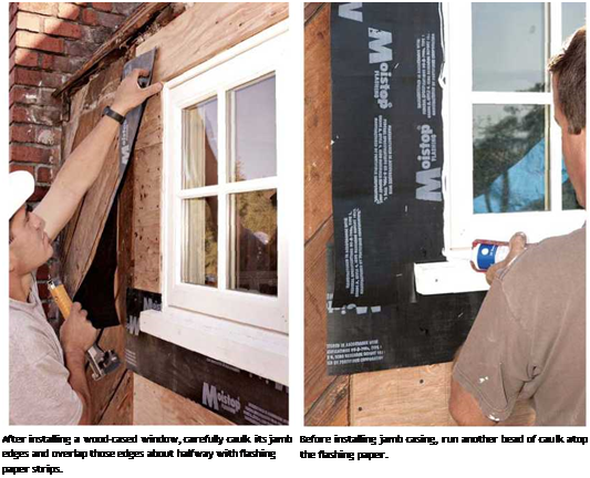
To seal side jambs, consider the double­caulking method shown above. Caulk each jamb edge, embed a flashing-paper spline in the caulk, and then run another bead of caulk atop the spline before installing the jamb casing. This caulk-and – spline sandwich stops infiltration effectively. Finally, caulk the edge of the head jamb before installing the head casing, but do not insert a spline between the head jamb and the casing— that could direct water behind the head casing.

After the window is cased, add the (metal) cap flashing over the head casing. Before installing flashing paper over metal flashing, careful
builders first caulk the upper flange of the flash­ing. This will prevent water that gets under the siding from wicking back up under the paper when it hits the window head. This is especially important with stucco siding, which is water per­meable and often collects water between the stucco and the building paper. Chapter 6 offers more specifics about cap flashing.

Should jamb flashing go over or under the building paper covering the sheathing? It doesn’t really matter because the strip flashing is extra protection. But under the windowsill, leave the lower edge of the flashing spline unstapled so it can overlay the building paper or housewrap below.

Windows and doors with integral nailing flanges require slightly different detailing. If the flanges are metal, apply fiberglass-reinforced flashing paper along the bottom and sides of the RO first. Then apply a bead of exterior caulk around the perimeter of the paper—close to the edges of the opening—and set the unit over the flashing paper. Position and shim the unit; then nail or screw through the flanges, into the sheathing. Install cap flashing (some units have an integral cap flashing) over the head of the unit, caulk its upper flange; then install flexible flashing over that cap flange. Building paper above will overlay the flexible flashing. Note: Most flanged windows don’t have casing per se. Unlike wood-cased windows, flanged units have jambs that protrude above the surface of the

Подпись: PROTIP Apply caulk around rough openings, rather than to the back of window or door casings. If you caulk the back of the casing instead, you're more likely to get sticky fingers while handling the unit. Caution: Positioning and shimming windows and doors may break caulk seals, so you should recaulk the perimeter once you've secured the unit. 1111 sheathing, so siding (or casing) is butted to the sides of these protruding jambs.
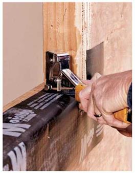
Exterior Trim

In appearance, exterior trim is sometimes ornate and complex, but its basic function is to cover critical building seams.

INSTALLING BUILDING PAPER

Installation techniques for housewrap and build­ing paper are much the same; in this chapter, both materials are often referred to generically as building paper.

Before starting, survey the sheathing and knock down protruding nail heads and wood sliv­ers that could puncture the paper and admit water.

Installation is two-person job, especially if you’re working with 9-ft.-wide rolls of Tyvek. As one person unrolls the material, the other aligns and staples it. Start at the bottom of the wall, overhanging the bottom edge of the sheathing by about 1 in. Position the building paper, tack an upper corner in place, roll out about 8 ft., and raise or lower the roll till the edge of the building paper is roughly parallel to the bottom edge of the sheathing. When it’s in position, staple the paper every 16 in. along the edges and every 24 in. in the field; use!4-in. or Мб-in. staples. Thereafter, roll out 3 ft. to 4 ft. at a time, stapling as you go. Trim the 1 in. overhang later.

As you roll out the building paper, make sure it lies flat to the sheathing. Otherwise, puckers can elevate the siding or trim applied over them, compromising weather tightness. Typically, the person holding the roll maintains a slight tension on the building paper to prevent puckers. Also, take care to avoid tearing the membrane while handling and stapling it—more of a problem with paper than with plastic housewrap, which stretches.

Overlapping and taping seams. Overlap verti­cal end seams by 4 in. to 6 in.; overlap horizontal seams 6 in. to 8 in. As you work up the wall, applying courses of building paper, upper courses should always overlay those below so any water that gets behind the siding is directed out and down, away from the sheathing. Building paper should also overlay any flashing, especially cap flashing over doors and windows.

Seal building-paper seams, tears, and punc­tures with seam tape; smooth down the tape to make sure it adheres well. If you’re installing plastic housewrap, use a seam tape recommended by the manufacturer. If you tear building paper, just staple a patch of the same material over it and apply caulking over the top edge. Last, install siding as soon as possible after installing the building paper because wind can lift and stretch it, especially plastic housewraps.

image269

To weatherproof windowsills, fold flashing paper strips into the rough opening, staple the paper down, and apply caulking. When the window is installed, its sill will compress the caulk, creating a positive seal. Tuck building paper or housewrap up under sill flashing.

Corners and rough openings. Take special pains with corners. Although a 4-in. overlap is often adequate for corners, you’ll be safer to over­lap outside corners by 1 ft. In addition, many builders reinforce corners with a self-adhering flexible flashing to keep water out should corner boards or siding gap. To prevent the material’s bunching in inside corners—a common problem with building paper—use a straight furring strip to press the paper into the corner before stapling it. That done, tape the corner seams immediately— before wind has a chance to lift the paper.

Builders installing plastic housewrap usually roll it right over rough openings (ROs) for win­dows and doors, cutting an Xin the middle of the opening and folding the housewrap into the sides of the framing. Well, that method can’t hurt. But it’s doubtful that it truly waterproofs the opening. If you’re installing metal windows, maybe a layer of housewrap will isolate the moisture that con­denses on cold metal. But if flashing paper is correctly installed about the perimeter of the window or door, water shouldn’t enter the RO in the first place.

Happiness Is My Own Bedroom

Подпись: [Photo Larry Haim)

CONTRARY TO WHAT PEOPLE MAY

think, having a lot of brothers is not always fun. I know. I am the only girl in a family with six children. When there are so many kids, vou need a big house, but our family could not afford one.

We used to live in a very small house with just two and a half bed­rooms. This may sound funny, but there were only two bedrooms, plus a space next to the washer and dryer where my oldest brother slept. My parents and baby brother slept in one of the bedrooms, and the other bed­room was for my other three brothers and me. My oldest brother didn’t have much room next to the washer and
dryer, but at least he didn’t have to share a room with three brothers.

Sharing a room with so many

O t

brothers was not much fun for me or for them. But one day when 1 came home from school, I heard some very exciting news. My parents sat us all down in the living room and told us that we were being given the oppor­tunity to get a bigger house by an organization called Habitat for I lumanity. I just kept thinking about the bedroom that they told me I’d have all to myself. I could hardly sleep that night.

We now live in our Habitat home. Habitat really helped my family and changed my life forever.

-Ashley Hanners

frames square. This makes for quality con­struction and an easier time nailing the top and bottom plates.

Distribute studs, corners, and channels

Ask your crew to distribute studs along one ol the exterior through walls, with one stud per layout mark. Place the studs against the two tacked-down plates. Where corners and chan­nels are required, decide which corner style you want to use. The sidebar on the facing page explains the main types of corners and channels. You can build corners and channels in place as you frame the walls, or you can build them all at once in a central location.

then distribute them and insert them in the walls as needed.

Keep your eyes open for studs that are bowed, twisted, or crowned. Set them aside to use for blocking and roof braces. This ensures a more uniform finished wall and makes it easier for finish carpenters to install cabinets, countertops, and interior trim. Its always good to think about how to make future tasks easier.

Nail on the top and bottom plates

It’s finally time to pry apart the two wall plates, that you tacked together in step 2. Working on one wall at a time, separate the top wall plate