Structural Steel

Steel for bridges is available in several different strength levels, each of which may be specified under ASTM A709, Standard Specification for Structural Steel for Bridges.

TABLE 4.1 Steels for Bridges

ASTM designations

Bridge

Structural steel

AASHTO

Type of steel

specification*

specification

designations

Structural carbon

A709 grade 36

A36

M270 grade 36

High-strength, low-alloy

A709 grade 50

A572 grade 50

M270 grade 50

High-strength, low-alloy

A709 grade 50W

A588

M270 grade 50W

Quenched and tempered

A709 grade 70W

A852

M270 grade 70W

high-strength, low-alloy Quenched and tempered,

A709 grade 100/

A514

M270 grade 100/

high-strength alloy

A709 grade 100W

M270 grade 100W

Control rolled

A709 grade HPS-50W

Quenched and tempered,

A709 grade HPS-70W

M270 grade HPS-70W

control rolled, interrupted accelerated cooled

Quenched and tempered

A709 grade HPS-100W

*When the supplementary requirements of A709 are specified, the steel exceeds the requirements of the listed structural steel specification. The supplementary requirements include toughness testing, grain size, and frequency of tension tests.

The grade designations are indicated in Table 4.1, as well as some alternative specifications that may be more familiar. The grade designation indicates the specified minimum yield stress in kips per square inch, and a “W” indicates that it is a weathering steel composition. ASTM A709 contains supplementary requirements for notch toughness and other items that are available but apply only when specified by the purchaser. When such supplemen­tary requirements are specified, they exceed the requirements of the basic specifications such as A36 or A572.

The HPS designations indicate that the materials are high-performance steels. They are so designated because they possess superior weldability and toughness compared to conventional steels of similar strength. Grades 36, 50, and 50W are available either as structural shapes or as plates. The other grades are available only as plates. Grades 36, 50, and 50W are the most frequently used materials. In general, compared with A36 steel, where other limitations such as deflection or stiffness do not override, the extra unit cost of the higher-strength grades (50 or 50W) is more than offset by the higher – yield strength. Grades 70W and 100/100W have proven economical in longer-span structures, or the higher-stressed portions of medium-span structures. The AASHTO publication Guide Specification for Highway Bridge Fabrication with HPS-70W Steel suggests that economies can be achieved by combining the use of HPS-70W and Grade 50W steels in a structure. In a 181-ft (55-m) span bridge for the New York State Thruway Authority, the use of HPS-70W steel reduced the number of girders in the cross section from five to four, enabling a savings of 28 percent in weight and 18 percent in cost.

Weathering grades (50W, 70W, and 100W) have chemical compositions that pro­vide enhanced resistance to atmospheric corrosion. They can be used in the bare (unpainted) condition for bridges in many cases (see Art. 4.13). The savings on cost of painting and repainting frequently makes them an economical choice.

Although prices vary widely due to demand and availability, in reference to the unit price of grade 36 steel, the relative material price of the other steels in plate grades is approximately as follows:

Grade

Price relative to A36

36

1.00

50

1.12

50W

1.23

70W

1.52

100W

2.07

As indicated, these are only price factors and do not consider the reduced quantity of steel that may be required as the yield strength increases. For structural shapes, grade 50 steel can usually be obtained for about the same price as grade 36 steel, but there would usually be some additional cost for grade 50W.

The cost of fabrication and erection for members of grade 36 and grade 50 or 50W steel is approximately the same. Thus, in preliminary cost studies, only the cost of the mill material for the members selected need be compared. Fabrication costs for grade 70W, grade 100, and grade 100W tend to be higher than those of the as-rolled products, and thus, the cost comparisons must include those costs.

Steels with greater strength than grade 36 tend to be economical for beams and girders in many cases, and are particularly attractive under the following conditions:

• When dead load is a major part of total load

• When deflection limits do not control

• When deflections can be reduced (composite design, continuous structure, etc.)

• When weight reduction cuts cost of foundations, shipping, etc.

• When selection avoids use of built-up members (cover plates, fabricated girder versus rolled beam, etc.)

The higher-strength steels often show advantage for tension members of trusses because the higher strength is used more effectively (for the entire depth of the member, because there is no stress gradient). The same is true for compression members of trusses where the member slenderness ratio is small to moderate (ratio of length to radius of gyration of about 80 or less, depending on grade).

Rain Gutters

Gutters direct water away from the house, pre­venting water from collecting next to the founda­tion and thereby possibly undermining it. The two most common gutter profiles are half-round and K-style, in which the gutter has a squared-off back and an ogee front. For appearance’s sake, try to match the profile of new gutters to old.

To clear water adequately, gutters must be sized properly and cleared of leaves and debris twice a year—in spring and in fall. Your lumber­yard probably has elaborate gutter-sizing charts based on regional rainfall, roof square footage, and pitch. But you might remedy chronically overflowing downspouts simply by upsizing the gutters from a standard 5-in. width to a 6-in. model and installing larger downspouts. To keep

image305

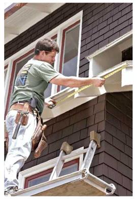
Begin any gutter installation by checking the slope of roof edges and trim and then measuring the areas to receive gutters. Typically, gutters extend beyond the roof section ‘h in. on each end. As you reconnoiter, consider where downspouts will be least obtrusive.

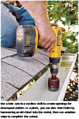
Подпись: Use a hole saw in a cordless drill to create openings for downspout outlets. In a pinch, you can also start holes by hammering an old chisel into the metal, then use aviation snips to complete the cutout.
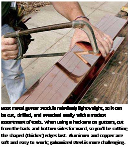
Подпись: Most metal gutter stock is relatively lightweight, so it can be cut, drilled, and attached easily with a modest assortment of tools. When using a hacksaw on gutters, cut from the back and bottom sides forward, so you'll be cutting the shaped (thicker) edges last. Aluminum and copper are soft and easy to work; galvanized steel is more challenging.

roof runoff from running behind gutters and rot­ting fascia, extend the roof drip-edge flashing so it overhangs the gutter.

If gutters are spaced too far from the roof edge or slope away from the drip-edge, you can place an L-shaped piece of metal flashing over the back of the gutter and tuck its upper edge up under the drip-edge. (Notch that flashing so it fits around the roof hangers.) Some К-style gutters also come with an integral flange that runs under the roofing and serves the same function as a drip-edge.

MATERIALS

Metal gutters can be fabricated on site by a gutter specialist with a mobile machine. Or you can assemble them from 10-ft. or 20-ft. prefab lengths, using pop rivets and exterior caulking. Plastic gutter sections need cementing. Gutter runs that are longer than 40 ft. need an expan­sion joint to keep them from buckling. Here are the materials most commonly used.

Aluminum. By far the most popular, aluminum resists corrosion, is easily worked, is reasonably priced, and is durable—though it will dent. It comes prepainted in a range of colors. Standard thickness is 0.028 in., but spending a little more for 0.032 in. is prudent, especially if heavy snows and ice dams are common in your area.

Galvanized steel. Stronger and harder to dent than aluminum, galvanized steel rusts if you don’t keep it painted. There are prepainted vari­eties, generally in the same colors as painted metal roofs. The minimum thickness is 26 gauge.

image308

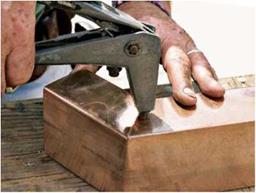
For gutters, a pop riveter is indispensable for joining because, unlike screws, pop rivets don’t intrude into the gutter or downspouts and so won’t snag leaves and cause clogs. Predrill pop-rivet holes.

Copper. Handsome when new, copper acquires a beautiful green patina as it weathers. It’s mal­leable, durable, and about five times as expensive as aluminum. This gutter is usually formed from 16-oz. sheet copper. Copper resists salt air but may be corroded by cedar-shingle runoff.

Plastic. Plastic comes in 8-ft. and 10-ft. lengths, with matched fittings. You can join sections either with liquid cement or with neoprene gas­kets. It’s virtually maintenance free and durable, if the plastic contains a UV inhibitor. Its expan­sion joints can accommodate a wide range of movement.

BASIC BRIDGE MATERIALS

The basic materials most often used to construct bridges are concrete and steel. Timber is occasionally used for deck construction and sometimes for short-span bridges.

4.5.1 Concrete

High strength is desirable for bridge concrete to reduce member size and weight, but durability is equally or more important. Component materials must be compatible with each other, and the concrete must have low permeability.

A long-term destroyer of concrete from within is alkali-silica reaction. While material specifications for concrete have been developed to preclude use of cement and aggre­gates that will produce alkali-silica reaction, the best prevention of this problem is the use of cements and aggregates from sources that have a known history of absence of this problem.

Given that required strength can be obtained by mix design with relative ease, low permeability becomes one of the most desirable properties, because bridge concrete is reinforced or prestressed and prevention of corrosion of the embedded steel is essential for long-term durability. Reduced permeability will also reduce carbonation, alkali-silica reaction, and freeze-thaw damage. Permeability can be reduced by proper mix design, by maintenance of a low water/cement ratio during concrete placement, by use of admix­tures, by compactive effort, by use of specialty concretes, or by application of concrete sealers or coatings. Often a combination of these procedures is employed.

Another desirable quality for the prevention of reinforcing steel corrosion, along with low permeability, is resistance to cracking. The cracking of bridge decks and of bridge deck overlays has been a persistent problem. The use of shrinkage-compensating con­crete using type K cement has been found to be effective in reduction of cracking, and some agencies mandate its use in construction of bridge decks. One property of shrinkage – compensating concrete that is different from regular concrete is the need for adequate amounts of mix water to cause the chemical reaction necessary for the development of the expansion. The normal rules of low water-cement ratio do not apply and must not be enforced. Another difference is that bleed water cannot be expected to appear. Waiting for bleed water to appear will result in the start of concrete hardening, making finishing very difficult. Agencies that have adopted shrinkage-compensating concrete have also adopted strict specifications for the production, placement, and curing of the concrete.

These specifications address the requirements peculiar to shrinkage-compensating concrete, but also include many requirements that are applicable to normal concrete as well. Perhaps the most important requirement is that prior to placement of the deck concrete, a preconstruction meeting be held, and that all participants in the cement manufacturing and concrete mixing, delivery, placement, finishing, curing, and inspection be required to take part. This meeting gives the type K cement manufacturer the opportunity to instruct the other participants in special requirements, and to correct any misconceptions that exist. Such meetings in themselves go a long way toward improving the quality of the concrete.

Admixtures. Various admixtures are available to enhance the properties of concrete made with the basic ingredients: coarse aggregate, fine aggregate, portland cement, and water. Admixtures may be classified as chemical admixtures such as air-entraining, water-reducing, set-retarding, accelerating, or superplasticizer; and mineral admixtures such as fly ash, silica fume, or slags. Mineral admixtures are usually added to concrete to improve workability, and resistance to thermal cracking and sulfate attack; and to reduce cement content whereas the chemical admixtures are added for entrainment of air, reduction of water or cement content, plasticization of the mixture, or control of setting time.

Air-entraining admixtures produce a distribution of bubbles that become permanent tiny voids in the concrete. This system of voids makes the concrete resistant to scaling, a surface failure that became frequent when deicing salts came into use. Air entrain­ment has virtually eliminated scaling. The use of air entrainment is recommended even with high-strength concrete.

Water-reducing admixtures make concrete mixtures workable at a lower water/cement ratio than is possible with use of “water of convenience” (water in excess of that required for hydration of the cement) alone. High-range water reducers provide great workability at very low water/cement ratios, and have been developed to provide reasonable control of duration of extra fluidity.

Dense concrete is a concrete developed by the Iowa Department of Transportation for overlayment of new and existing concrete bridge decks. It has a low water/cement ratio and relies on special compactive effort imparted by vibrating screeds to produce a dense concrete with reduced permeability.

Latex-modified concrete uses an admixture of latex, generally liquid styrene butadiene with a minimum solids content of 40 percent. It achieves a reduced permeability equivalent to dense concrete at a lesser thickness. This quality is important to the via­bility of latex-modified concrete as an alternative option to dense concrete because the cost of latex-modified concrete is higher on a volume unit measure basis.

Silica fume concrete, or microsilica concrete, incorporates extremely fine particles of microsilica. Added to concrete in powder or liquid form, it densifies the concrete, increases strength, and reduces permeability. Where silica fume concrete has been allowed as a contractor’s alternative option to latex-modified or dense concrete, it has rapidly replaced these other specialty concretes.

Calcium nitrite concrete contains calcium nitrite, a widely used inorganic corrosion inhibitor that acts at the surface of the steel reinforcement to limit the electrochemical reaction involved in the corrosion process. The calcium nitrite is added in liquid form to the concrete at a rate of 3 to 5 gal/yd3 (15 to 25 L/m3), depending on the quality of the concrete, the level of chlorides expected, and the life required for the concrete. (See Manual for Corrosion Protection of Concrete Components in Bridges, Task Force 32 Report, February 19, 1992, AASHTO, Washington, D. C.)

High-Performance Concrete. High-performance concrete (HPC) is defined as con­crete that meets special combinations of performance and uniformity requirements that cannot be achieved routinely using conventional ingredients, normal mixing and placing procedures, and typical curing practices. HPC offers many strength-related improve­ments such as higher compressive strength and modulus of elasticity, and lower creep and shrinkage. It also offers ductility-related improvements such as increased resistance to freeze-thaw, abrasion, and scaling, as well as reduced permeability. Potential benefits to owners include lower initial and life cycle costs as a result of lower construction costs, less required maintenance, longer structure life, and elimination of additional pro­tective systems. Also, there should be less disruption to the public due to the decreased maintenance requirements and longer periods between major rehabilitations.

HPC qualifies for the special federal funding allocated by the U. S. Congress (fiscal 1998 to 2003) for repair, rehabilitation, replacement, and new construction of bridges or structures that demonstrate the application of innovative materials. Missouri, Nebraska, New Hampshire, Texas, Virginia, and Washington are included in the AASHTO Strategic Highway Research Program (SHRP) lead state team for HPC implementation. HPC program bridges have already been constructed in several states including Texas, Nebraska, Virginia, Washington, New Hampshire, and Colorado. HPC bridge decks have been designed and either built or scheduled to be constructed in Ohio, New Jersey, and Puerto Rico.

HPC mixes must use pozzolan materials such as silica fines and fly ash. Pozzolans make concrete denser, thereby increasing durability. Silica fines eliminate the detri­mental effects of fly ash on concrete mechanical properties. Fly ash reduces the heat of hydration and thereby reduces plastic shrinkage. Mix design requirements vary, depending upon the application. For bridge decks, states have specified a 28-day com­pressive strength from 4000 to 8000 lb/in2 (27.6 to 55.2 MPa), and from less than 750 up to 2000°C for chloride permeability. For prestressed concrete beams, states have specified a 28-day compressive strength from 6000 to 10,000 lb/in2 (41.4 to 69 MPa), and from less than 1000 up to 2000°C for chloride permeability. The minimum specified for silica fines has ranged from 5 to 10 percent. Curing requirements have included a wet burlap covering within 10 min of finishing, and a 7-day wet cure followed by application of a curing compound.

HPC specifications typically also include production, placement, and curing trials. Testing programs include evaluations of strength, permeability, scaling, freeze-thaw, abrasion, elasticity, creep, and shrinkage. Not all tests are required for each application, but because many of the tests are of long duration, mix design may take 6 months or more.

Lightweight Concrete. Although the concrete most often used in bridge construction is normal-weight (hardrock) concrete having a unit weight, reinforced, of 150 lb/ft3 (24 kN/m3), lightweight concrete can be produced from manufactured aggregate that is available from several sources around the United States. The coarse aggregate is produced by heating shale in a kiln, which expands it. Lightweight fine aggregate can also be pro­duced but is not recommended for bridge concrete. Use of lightweight coarse aggregate can reduce the weight of reinforced concrete to 115 lb/ft3 (18 kN/m3). While the history of lightweight concrete for bridges includes premature failures, it also includes successful applications in both deck slabs and beams. It is important to recognize the different (greater) creep characteristics of lightweight concrete in structures where long-term deflec­tions are a significant design factor.

Hydraulics in the Mycenaean civilization in the second millennium BC

At the beginning of agriculture in Greece, Vth millennium BC, the abundant precipita­tion of spring and autumn obviated the need for irrigation. But irrigation eventually does develop in the Greek world. The earliest written reference to it comes from the Iliad:

“As one who would water his garden leads a stream from some fountain over his plants, and all his ground-spade in hand he clears away the dams (blockages) to free the channels, and the little stones run rolling round and round with the water as it goes merrily down the bank faster than the man can follow (.. .)”n

The Mycenaen civilization that develops especially from 1600 BC is the cultural heir of the Cretan civilization. The Acheans are the heroes of the principal Greek myths, myths that are surely the distant echo of a measure of historical reality. Jason and his quest for the golden fleece are the story of a commercial maritime voyage – or of plun­der. The adventures of Theseus and the Minotaur reflect the antagonism between the Acheans and the Minoans. The myth of Hercules, who changed the course of a river to clean the stables of Augias, surely echoes the mastery of river engineering that we illus­trate further on.

Methods of Earth Construction

Earth is widely available at little or no cost. It is nonflammable, is infinitely recyclable, is

Подпись: J

condensing. Even if water does condense, there is always an exit pathway for it. Natural building materials such as earth, cob, and masonry are es­pecially well suited for this task. To create a fully functional wall based on the flow-through design, any healthy home project must take into account all the climate-specific details of its location.

a. Max von Pettenkofer. Uber den Luftwechsel in Wohngebauden. Literarisch-Artistische Anstalt der J. G. Cotta’schen Buchhandlung, 1858.

b. Erwin Raisch/’Die Luftdurchlassigkeitvon Bau – stoffen und Baukonstruktionsteilen." Gesund- heitsingenieur. Issue 30 (1928).

c. Winfried Schneider. "40 Jahre Baubiologie – Klischees, lnnovationen, Trends."l/l/o/mung und Gesundheit. V0I.120 (2006), pp. 12-14. See also baubiologie. de/site/zeitschrift/artikel/120/12 .php.

d. M. Stiicker et al.’The Cutaneous Uptake of Ox­ygen Contributes Significantly to the Oxygen Supply of Human Dermis and Epidermis."Jour­nal of Physiology. Vol. 538 (2002), pp. 985-994.

e. W. Schneider and A. Schneider. Baubiologische Boustoffiehre + Bauphysik. Course Module 7 of

IBN Building Biology Correspondence Course 1998, p.67.

f. Moisture uptake of building materials within three hours while ambient air humidity in­creased from 40 to 80 percent. W. Schneider and A. Schneider. Baubiologische Boustoffiehre + Bauphysik. Course Module 7 of IBN Building Biology Correspondence Course 1998, p. 37.

Katharina Gustavs, BBEC, CT, is a Building Biol­ogy environmental consultant living on Vancou­ver Island, British Columbia, who specializes in electromagnetic field testing and healthy lifestyle programs for environmentally sensitive individu­als. As a professional translator, she is also translat­ing and researching the original Building Biology Correspondence Course from Germany for the International Institute for Bau-Biologie & Ecology in Florida. Contact her at gustavs@buildingbiol ogy. ca.

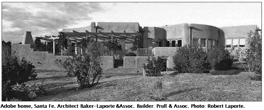
Подпись: Adobe home, Santa Fe. Architect Baker-Laporte &Assoc. Builder: Prull & Assoc. Photo: Robert Laporte.
not subject to insect infestation, is a natural preservative, has excellent thermal mass stor­age capacity,3 has the ability to handle large amounts of water vapor diffusion and stabi­lize humidity without mechanical augmenta­tion, and, unlike postindustrial manufactured building materials, has a proven record of lon­gevity with intact examples dating back more than 7,000 years.

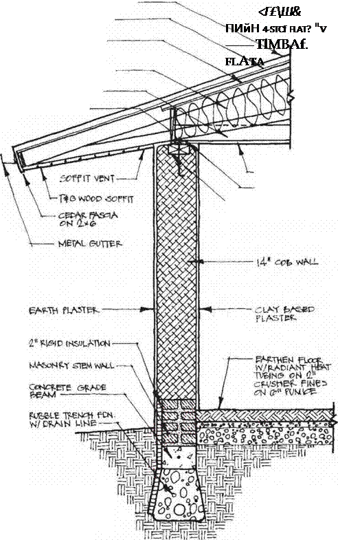
Earth is the predominant preindustrial building material. Earth construction, in all of its various forms, has not been codified on a national level in this country, and in spite of the fact that it is the wall-building material for more than a third of the worlds homes its use is considered by most building departments to be experimental. In Germany, simple stan­dardized tests for measuring various struc­tural properties of mud have been developed and codified. The work done there could pave the way for wider acceptance here if more per­formance-based criteria for code compliance are permitted in the future. For the most part, approval is currently at the discretion of the local building authority.


Earth Block Construction

Earth block construction is used in every hot, dry subtropical climate throughout the world. Examples have been found in Turkestan dating back to 6,000 BC. The historical core of Shi – bam in Yemen, consisting of eight-story build­ings, is constructed entirely of adobe. These magnificent buildings have scarcely been al­tered since the time of their last rebuilding in the mid-i6th century.

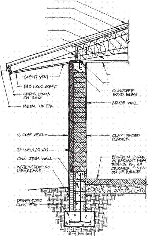
Earth blocks are primarily used in mod­ern construction in three forms. Adobes are mixed wet, poured into formwork, and then sun dried. Pressed blocks are made from moist soil that is compacted by a mechanical or hand press. Green bricks are extruded in a brick-making plant and used unfired.

In the US Southwest, adobe is a traditional building material that has remained in contin­uous use and is the material of choice for some of the most exclusive residences being built today. It has been jokingly called the building material for “the idle rich” or “the idle poor” because stacking the heavy blocks is labor in­tensive.

Methods of Earth Construction

Because the R-value4 of earth blocks is fairly low, walls require additional insulation to meet energy requirements in all but the warm­est parts of North America. A higher R-value is usually obtained by adding foam insulation to the exterior of the building, which affects the “breathability” of the wall and creates a dubious marriage between natural and syn­thetic materials. Although most earth block is currently used in desert climates and for exte­rior wall construction, its excellent mass and

acoustic properties make it a superb product for interior mass walls in any climate where it is available or can be produced.

Adobe blocks are frequently “stabilized,” mainly to make them more water resistant and to prevent breakage during transport. The most common stabilizer is asphalt, a car­cinogenic material that should be avoided in the healthy home. Unstabilized adobes can be purchased from some adobe yards and can be special-ordered. Compressed earth blocks can

Methods of Earth Construction

Home of Professor Gernot Minke showing the "stranglehnTwall components.

Photo: Robert Laporte.

be made onsite with an adobe press, thereby eliminating the need to protect blocks during transportation. However, earth blocks that are not stabilized must be protected from ground water damage. This can be accomplished by holding the first course of blocks off the floor by installing a layer of concrete block first.

New Mexico has developed its own com­prehensive code for load-bearing adobe con­struction, which has served as a model for parts of Colorado and Arizona.

WET VENTING

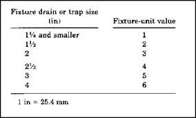
Wet venting is popular, but a little different when it comes to sizing the vents. Tables can still be used for this type of sizing. Look at Figure 5.34 for an ex­ample of a table that might be used to size a wet stack vent. Another type of table that you might encounter is shown in Figure 5.35. This table is intended for use in sizing a vent stack for wet venting.

Keep in mind that not all plumbing codes are the same, and they may present their information differently. It is also important to remember that re­quirements may be different.

Fixture-unit value as load factors

Minimum siz trap (in)

2

U/2

2

2

3

3

1У>

8

3

3

3

2

2

4

1У2

8

Note 6

4

Note 6

4

Note 6

3

2

2

Nominal 1У2

3

Note 6

4

Note 6

6

Note 6


Fixture type

Laundry tray (1 or 2 compartments)

Shower stall, domestic Showers (group) per head2

Sinks

Surgeon’s

Flushing rim (with valve) Service (trap standard)

Service (“p” trap)

Pot, scullery, etc.2

Urinal, pedestal, siphon jet, blowout

Urinal, wall lip Urinal, Washout Washing machines (commercial)3 Washing machine (residential)

Wash sink (circular or multiple) each set of faucets

Water closet, flushometer tank, public or private

Water closet, private installation Water closet, public installation


1 in = 25.4 mm

Notes:

1. A showerhead over a bathtub or whirlpool bathtub attachments does not in­crease the fixture value.

2. See Figures 12.33 and 12.34 for methods of computing unit value of fixtures not listed in Figure 12.32 or for rating of devices with intermittent flows.

3. See Figure 12.33.

4. Lavatories with VA or 1 Winch trap have the same load value; larger P. O. plugs have greater flow rate.

5. Size of floor drain shall be determined by the area of the floor to be drained. The drainage fixture unit value need not be greater than 1 unless the drain re­ceives indirect discharge from plumbing fixtures, air conditioner or refrigeration equipment.

6. Trap size shall be consistent with fixture type as defined in industry stan­dards.


FIGURE 5.32 ■ (Continued) Fixture units per fixture or group. (Courtesy of Standard Plumbing Code)


WET VENTING

FIGURE 5.33 ■ Fixtures not listed. (Courtesy of Standard Plumbing Code)


Stack pipe size Fixture-unit load on stack Maximum length of stack (ft)


30

50

100

300


2

4

3

24

4

50

6

100


WET VENTING Подпись: Vent-stack size requirements (in) 2 2‘/2 3 4

FIGURE 5.34 ■ Table for sizing a wet stack vent in Zone Two. (Courtesy of McGraw-Hill)

FIGURE 5.35 ■ Table for sizing a vent stack for wet venting in Zone Two. (Courtesy of McGraw-Hill)

BRIDGE GEOMETRICS

Bridge Width. Roadway width on bridges is the inside measurement to the bottom of the sidewalk curb or the bottom of the safety barrier. For bridges on roads where sidewalks are not provided, the bridge width is made equal to the approach roadway width including shoulders, so that the bottom of the barrier curb or the near face of the railing is aligned with the face of the barrier rail at the outside edge of the shoulder.

In the past, policy did not always permit full shoulders to be accommodated on bridges. Often the roadway was made narrower, particularly on longer bridges. This was done strictly to reduce bridge cost. From the traffic operations standpoint, however, it was an unwise practice. Disabled vehicles could not find refuge on the shoulder, and a full shoulder was not available for temporary maintenance of traffic during road rehabilitation or repaving. It is now recognized that a bridge is an integral part of a highway system when it comes to roadway width. The FHWA requires a minimum shoulder width of 8 ft (2.4 m) on each side of the roadway on federally funded projects.

Bridge Horizontal Clearance. For bridges over streams, the location of substructure units, and therefore the length of spans, is controlled by hydraulic requirements and by nav­igation clearance requirements established by agencies such as the U. S. Coast Guard and the U. S. Army Corps of Engineers. For bridges over navigable waters, the bridge designer should also consider the possibility of collisions from vessels. Refer to AASHTO’s Guide Specifications and Commentary for Vessel Collision Design of Highway Bridges.

For crossings of highways, the bridge columns or pier walls should clear the traveled way, shoulders, ditches where required, barrier rail, and any additional width required to provide a safe clear zone from edge of pavement. A minimum clearance of 30 ft (9.1 m) from edge of pavement is required except where this clearance is impractical, in which case the pier or wall may be placed closer to the edge of pavement, with barrier rail 2′-0" (610 mm) minimum from edge of shoulder, and pier or wall 2′-0" (610 mm) minimum from face of barrier rail. The barrier rail offset from face of pier or wall will be further controlled by the dynamic deflection of the particular system used. (See Chap. 6 for additional information.)

For crossings over railroads, the horizontal clearance requirements are usually set by the railroad company or by the state public utilities commission. In addition to clearance for safe operation of trains, including allowance for accidentally overhanging cargo, rail­road companies are cognizant of the importance of trackside drainage and require that drainage ditches be accommodated where present. In addition, a maintenance roadway for off-track equipment is often required. A horizontal clearance of 25 ft (7.6 m) from the centerline of the track is desirable and will obviate the need for pier crash walls.

If a pier adjacent to a railroad track is located closer than what is considered to be an adequate distance to prevent derailed cars from striking the pier (generally 25 ft (7.6 mm) from centerline of railroad track), the pier is required to be of heavy construction, or a sub­stantial crash wall is required to be constructed to protect the pier and prevent catastrophic collapse of the bridge. This wall should be aligned with the pier. For additional details, refer to the American Railway Engineering and Maintenance-of-Way Association (AREMA) Manual for Railroad Engineering.

AASHTO LRFD Specifications require abutments and piers located closer than 30 ft (9.1 m) to the edge of the roadway or closer than 50 ft (15 m) to the centerline of a railway track to be designed for a vehicular collision load defined in the specifications, unless protected by an embankment or a structurally independent, crashworthy, ground – mounted barrier.

Bridge Vertical Clearance. Generally, a clearance of 16 ft (4.9 m) plus an allowance for resurfacing should be provided over major state, U. S., and interstate highways, over the entire width of roadway. Over less important highways, a clear­ance of 14 ft (4.3 m) should be provided. These are AASHTO requirements. Published state standards, if different from AASHTO, should be followed.

The above vertical clearances apply to vehicular bridges. Because pedestrian bridges are narrower and lighter in weight, and therefore more vulnerable to major damage or collapse in the event of collision from overheight vehicles passing under the bridge, states are beginning to require an additional clearance of 1 ft (300 mm) for pedestrian bridges. This additional clearance is also recommended for overhead sign structures.

Vertical clearance requirements over railroads, like horizontal clearances, are set by the railroad company or state public utilities commission. A minimum clearance of 23 ft (7.0 m) above high rail is common for new bridges over nonelectrified racks. If the tracks are electrified, an additional 1-ft (300-mm) minimum clearance is required for catenary wires. Widened or rehabilitated bridges will generally be allowed to maintain the existing clearance, but no less.

Vertical clearance requirements over navigable waterways are subject to bridge permits by U. S. Coast Guard (USCG). USCG has established guide clearances for particular waterways. They are not regulatory in nature and greater or lesser clearances meeting reasonable needs of navigation for a particular location may be required or approved by USCG.

Wall

T

he walls of a building serve several important functions: They define the spaces within the building to provide privacy and zoning, and they enclose the building itself, keeping the weather out and the heat or cold in. Walls provide the vertical structure that supports the upper floors and roof of the building, and the lateral structure that stiffens the building. Walls also encase the mechanical systems (electrical wiring, plumbing, and heating). To incorpo­rate all of this within a 4-in. or 6-in.-deep wood-framed panel is quite an achievement, so numerous decisions need to be made in the course of designing a wall system for a wood-frame building. There are two pre­liminary decisions to make that establish the framework for the remaining decisions.

wall thickness

Should the walls be framed with 2x4s or 2x6s? The 2×6 wall has become increasingly popular in recent years, primarily because it provides more space for insulation and allows for other minor energy-saving advantages (such as the ability to run electricity in a notched base, as shown in 73A). These advantages all come at some cost. A 2×6 wall with studs spaced 24 in. o. c. (the maximum spacing allowed by codes) uses about 20% more material for studs and plates than a 2×4 wall with studs with a code-allowed spacing of 16 in. o. c. On the outside, the sheathing has to be V2 in. thick (Tbs in. thicker than sheathing on a stan­dard 2×4 wall). Inside, the drywall also has to be Vs in. thicker to span the 24-in. spacing between 2×6 studs. Thicker insulation costs more too. So, overall, 2×6 framing makes a superior wall, but one that costs more. Framing the exterior walls with 2x6s and interior walls
with 2x4s is a typical combination when the energy – efficient 2×6 wall is selected. Stud spacing of 2×4 and 2×6 walls may vary with loading, lumber grades, and finish materials; in this book, however, studs are assumed to be 16 in. o. c. in 2×4 walls and 24 in. o. c. in 2×6 walls unless noted otherwise.

framing style

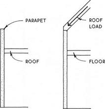
Should the walls be built using platform framing or balloon framing? Balloon framing, with studs continuous from mudsill to top plate and continuous between floors, was developed in the 1s40s and is the antecedent of the framed wall. In recent years, balloon framing has been almost completely superseded by the more labor-efficient and fire-resistant platform frame construction, with studs extending only between floors. There are still situations, however, where a variation of the balloon frame system is useful. One such situation is where the continuity of studs longer than the normal ceiling height is essential to the strength of a wall. Examples include parapet walls and eave (side) walls

Wall

WALLS

that must resist the lateral thrust of a vaulted roof (as in a i^-story building).

Balloon-framed gable-end walls also provide increased stability in high-wind areas (see 160).

Another reason for using balloon framing is to mini­mize the effects of shrinkage that occurs across the grain of joists in a platform-framed building. This could be important with continuous stucco siding that spans two floors without a control joint, or in a multiple-story hybrid building system where the floors in the balloon­framed part would not shrink equally with the floors in the platform-framed part.

The Breathing Wall Concept: Misconceptions

The breathing wall concept goes back to Max von Pettenkofer (1818-1901), one of the most accom­plished hygienists of his time and the pioneering founder of the occupational and environmental hygiene sciences as we know them today. He was instrumental in stopping the cholera epidemics in Munich, one of the largest cities in Germany, dur­ing the second half of the 19th century. By initiat­ing the construction of a central water supply and sewage treatment system, he greatly improved public health and achieved celebrity status.

In his dedicated search for better living condi­tions, von Pettenkofer introduced carbon dioxide measurement as an important indicator of over­all indoor air quality. His measurements of air ex­change rates in a room with brick walls, a masonry heater, and sealed windows led him to hypothe­size that the brick walls must let air pass through. Even with the keyhole and other cracks sealed, the air exchange rate dropped only about a quarter compared to the rate prior to sealing.3

He seems to have forgotten to consider the ef­fect the masonry heater would have on the ven­tilation rate. Thus he proceeded to demonstrate that when air is pumped through a brick cylinder,
sealed on the outside except for both ends, a can­dle flame at the other end could be extinguished. In his eagerness to prove his hypothesis, he over­looked the fact that the maximum natural air pres­sure across a wall of about во pascals is many times lower than the pressure required in his candle-ex­tinguishing experiment (between 700 and 10,000 pascals).

Von Pettenkofer’s celebrity status may have been one of the reasons his hypothesis of natural ventilation through walls was not scientifically de­bunked until the 1920s. b Though he never used the term "breathing wall," this concept took on a life of its own that continues to this day. The Insti­tute of Building Biology and Ecology Neubeuern in Germany recommends avoiding the use of the term because it does not reflect the reality of the complex processes occurring in a wall and usually leads to misconceptions.0

In Building Biology, a natural home is consid­ered to be a living organism in the sense that it should be — as much as possible — self-sufficient, energy-efficient, and built from materials that are part of the natural cycle and do not contribute to toxic waste. The roof and wall systems are often re­
wall made of unprocessed materials through which the flow of vapor is unhindered is called a breathing wall. The concept is central to the Building Biology goal of creating a healthy dwelling. (Tire term “breathing wall” is really a misnomer because the walls of course are not the primary ventilation source for the build­ing. The term “vapor-permeable wall” would perhaps be more accurate.) Another Building Biology concept is that of the building enve­lope being our third skin (clothing being our second skin). This analogy is a more useful one in describing how a breathing wall works. Our skin is the organ of contact with the outer en­vironment and regulates the balance of mois­ture and temperature of the body in relation to the environment. Skin must remain perme­able to facilitate a healthy interaction between the natural environment and the human or­ganism. So too, according to Building Biology,

ferred to as our third skin, implying that, just like human skin, the building envelope is in constant contact with the environment and plays a crucial rolein maintaininga healthy inner climate despite unfavorable weather conditions outside. Let us have a closer look at what does or does not perme­ate a wall with regard to air and moisture.

A constant supply of oxygen-rich air and the re­duction of carbondioxideareessentialtoa healthy indoor climate, but it is a misconception that walls can "breathe" air, especially massive walls built from earth, masonry, or solid wood, despite their varying degrees of porosity. The air pressure dif­ference between outdoor and indoor air is never high enough to promote an air exchange through such a massive wall. If air does get through a wall, it is not through the wall itself but through poorly sealed joints and cracks. This, however, is the least desirable way to supply fresh air because it pro­motes high heat loss in winter, makes for very un­pleasant drafts, and invites moisture problems.

To ensure the Building Biology recommended rate of about one complete change of air per hour, either mechanical ventilation with a heat recov­ery system or cross-ventilation through open win­dows several times a day is necessary. Massive wall systems are especially well suited for natural ven­tilation methods because their extraordinary heat storage capacity keeps heat loss at a minimum during brief opening ofthe windows in winter.

It is interesting to note here that human skin does not breathe air either. All oxygen for our in­ner organs is supplied by the air inhaled through the nose and mouth, which in keeping with the analogy of the third skin would be comparable to the windows and doors in a house. Though the outermost layer of our skin (up to 0.4 millimeters) can extract oxygen from the ambient air, the oxy­gen does not cross into the body. d

It is true that wall structures without vapor barriers allow for the free flow of moisture or wa­ter vapor. Moisture always moves from a warmer area to a colder one, from a higher vapor pres­sure concentration to a lower concentration. As a result, water vapor tends to flow from the inside out in the north and from the outside in down south. In mixed and moderate climate zones, it has a tendency to flow from the inside out dur­ing the winter and from the outside in during the summer.

must our third skin, the walls of our dwellings, remain permeable in order to achieve an opti­mal environment for health.

There is an intimate connection between the health of an individual and the health of the environment. All building processes in­volve the extraction of raw materials from nature and the disruption of the natural eco­system. The alternative materials and meth­ods described below use these materials in a minimally processed state with far less envi­ronmental impact than the highly refined and processed materials prevalent in conventional construction. When one considers that 40 percent of the material resources entering the global economy are related to the building in­dustry,2 it becomes clear that the building ma­terial choices we make have a global impact on the health of the ecosystem, the ultimate de­terminant of our own health.

In recent years, with renewed inter­est in environmental concerns and energy

Massive wall systems made from earth, clay, or solid wood also have a high capillary activity that is capable of wicking away liquid water. Though any wall system should be designed to prevent vapor condensation from occurring, the wicking capacity of natural building materials provides additional insurance that liquid water will not get trapped in the wall. This, of course, works only as long as all wall finishes are also highly permeable to water vapor.

The actual amount of water vapor an exte­rior wall can shuttle to the outside of a building is rather low. For example, in winter, when outside temperatures are low in northern and moderate climates, only about 1 to 2 percent of the indoor moisture can make it through a brick wall. e Again, it is obvious that the majority of the moisture that is usually generated inside a home needs to be re­moved through active ventilation, using windows and/or mechanical ventilation systems.

Building and finishing materials with a high moisture buffer or hygric capacity improve indoor air quality tremendously because they help miti­gate temporary humidity highs. Nearly all natu­ral building materials are highly hygroscopic, especially wood, earth, lime, and cellulose. Lime plaster (13 grams per square meter) or clay plas­ter (30 grams per square meter) can absorb large amounts of water vapor. But as soon as you fin­ish a lime plaster with a standard latex paint, wa­ter vapor absorption drops (to below 9 grams per square meter).f Therefore it is important to choose surface treatments that are highly permeable to water vapor, such as lime wash, silicate, or casein paint. Note that this moisture buffering effect re­lies on only the first 1 to 1.5 centimeters of the in­terior wall surface. Thus almost any wall structure can benefit from the moisture buffering effect of adding a material such as a clay plaster.

It is unclear why the breathing wall concept persists when it is riddled with misconceptions. What is clear, however, is that any building enve­lope has to meet two major challenges: first, not to let any water in and second, if water does get in, to let it out again. In contrast to the widespread use of polyethylene vapor barriers, which often makes no sense from a building science point of view, Building Biology favors the so-called flow­through design, which allows water vapor to pass through the wall assembly’s components without
efficiency, several alternative methods of building have enjoyed a limited renaissance among environmentally concerned home­owners, designers, and builders. Since the last edition of this book in 2001, the negative im­pact of human activity on the global environ­ment has become increasingly evident, and in our efforts to lessen this impact the green building movement has experienced expo­nential growth. The Bau-Biologie or Building Biology study course states that “there is al­most always a direct correlation between the biological compatibility and ecological per­formance of a given building material.” This statement is exemplified in the proper use of natural, minimally processed, and locally found and crafted building materials.

Small Leaks Add Up, So Seal Them All

U

sually, the greatest number of leaks comes from small perforations in the ceiling: metal electrical boxes, drywall seams, and any place a wire or pipe comes through from below. Use expanding urethane foam to seal holes around PVC vent pipe (1), in electrical boxes (2), and especially at ceiling-corner drywall seams (3). If any of the sealing comes under local regulations for fire-stopping or draft-stopping, then use fire – or smoke-rated foam or caulking.

4 I. /

Small Leaks Add Up, So Seal Them All