Block the Biggest Offenders

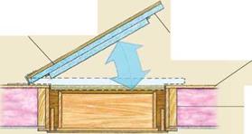
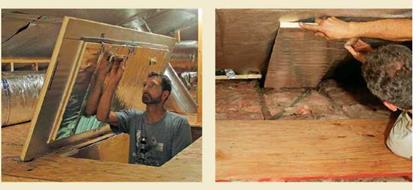
Block the Biggest OffendersПодпись: Ceiling joistПодпись: Two pieces of 1-in.-thick rigid-foam insulation glued to V2-in. plywoodПодпись: Foam weather-stripping acts as a gasket seal.Подпись: OSB deck acts as rimBlock the Biggest OffendersПодпись:Подпись: DrywallПодпись: SoffitBlock the Biggest OffendersПодпись:The attic access is a big leak that can be fixed quickly: Build or buy an insulated cover for the access bulk­head. The key is to provide a rim to connect to the sealing cover. The rim can be made from strips of sheathing, framing lumber, or rigid foam; then the cover sits on top or fits around the rim. On this job, I added a deck of leftover 1/2-in. plywood and OSB after the insu­lation was added.

Interior soffits that are framed before the drywall is hung can leak huge quantities of air. Fill in the openings between the ceiling joists above the soffits with solid materials like rigid-foam panels, drywall pieces, or sheathing scraps, then seal the edges with expanding foam or caulk.

Joist bays should be sealed with rigid blocks to keep insulation where it belongs. Cut rigid foam into strips the width of the joist bays, and slip them out over the top wall plate (photo at top right). The panels block the loose – fill insulation that’s to be installed from clogging the soffit-to-ridge air channel and add a higher R-value to the short space over the plate.

Block the Biggest Offenders

layered batts can be tight together to mini­mize heat loss through the joists and to maximize performance.

If I’m upgrading to loose-fill insulation,

I keep it from falling into eave soffits and maintain channels for roof ventilation by installing a layer of blocking made from rigid insulation in the rafter (or truss) bays over the exterior-wall plates. I notch the rigid insulation around the rafters so that I get a tight fit in the bay.

Blowing Insulation is a Two-Person Operation

Blown-in loose-fill cellulose or fiberglass isn’t as common as batt insulation, but both are installed quickly and completely cover the attic floor. Loose fill can be blown in over any existing insulation that’s been tuned up first. Comparisons in R-value be­tween the two are similar (around R-3.2 per in.). Over the first year, cellulose tends to

SLOPING AND PLACING GUTTERS

Ideally, gutters should slope down toward down­spouts 1 in. per 16 ft., but this is not always pos­sible. For starters, this may not look good: Next to a level fascia board, the steeper the slope of the gutter, the more it looks out of whack. As long as there is a slight pitch—say, І2 in. in 20 ft.—with no low spots en route to the downspout, a gutter will drain. If a house settles so that its roof edge or trim slopes away from downspouts, either install new gutters with downspouts properly located or raise or lower the gutters so they slope toward existing downspouts.

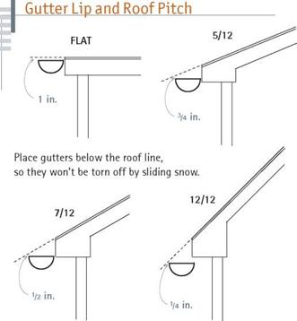
Place the front lip of the gutters below the roof plane, low enough so the sliding snow won’t tear them off yet high enough so the rain runoff won’t overshoot them. The distance below the projected roof plane varies with pitch: For a gently sloped 5/12 pitch, place the front lip of the gutter % in. below the projected roof plane; for a steeper 7/12 pitch, h in. below the plane; for a 12/12 pitch, /a in. The front lip of a gutter should always be about 1 in. lower than the back. That way, if the gutter overflows, water will spill over the front lip rather than soaking the fascia and siding behind.

INSTALLING GUTTERS

Reconnoiter the roof. Measure the length of the roof the gutter will service, and check the fascia (if any) and roof edge for level. Try to place the downspouts in an inconspicuous place, away from foot traffic. In positioning downspouts, the biggest challenge is usually on the uphill side of the house, where downspouts often require
underground drains to carry water beyond the outside house corners.

Next determine where you want seams, which should also be placed inconspicuously. Because gutter stock comes in 10-ft. or 20-ft. lengths, it might look better to join a 15-ft. length and a 10-ft. length to achieve a gutter 25-ft. long, rather than tacking a 5-ft. length onto the end of a 20-ft. length, if that joint would be near the front door.

image312

image313

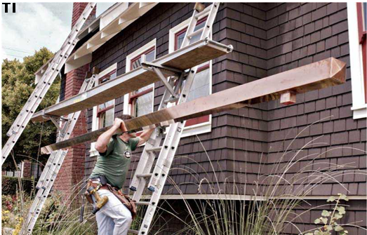
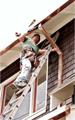
Although gutter sections are light enough for one person to carry, the job is safer and more

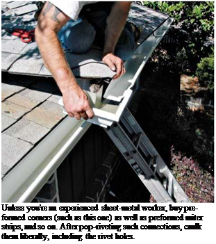
Подпись: Gutters are relatively fragile. Where you must replace a hanger or remove a gutter spike, use locking pliers to pull the fastener out; don't risk collapsing the gutter by attempting to pull spikes with a claw hammer. And where you must lean a ladder against gutters, place it near an internal support such as a spike- and-ferrule or a hidden hanger. 1111 Подпись:image314Подпись: Unless you're an experienced sheet-metal worker, buy preformed corners (such as this one) as well as preformed miter strips, and so on. After pop-riveting such connections, caulk them liberally, including the rivet holes.

predictable with two workers, especially if it’s windy. Snap a chalkline along the fascia to indicate the level of the hanger brackets and install a bracket at either end of the roof. Other­wise, snap a chalkline to indi­cate the back lip of the gutter.

If your gutter hangers fit into the gutters, position them before you carry gutter sections aloft; also, preassemble the end caps, downspout takeoffs, and so on.

Once you’ve secured either end of the gutter and checked its position, add hangers every 32 in. (every other rafter); in snow country, install a hanger every 16 in. The hangers you choose will deter­mine exactly how you secure gutters. Most mod­ular gutter systems can be cut to length with a hacksaw and joined with poprivets or self­tapping sheet-metal screws. A disadvantage of screws: Their points protrude, snagging leaves and causing blockages. An advantage: Screws can be removed to disconnect the sections.

Consequently, use rivets to join the gutter sec­tions, downspout outlets, and miter strips. And use the shortest screws feasible to join the down­spouts to the gutter outlets. To avoid galvanic corrosion, use screws that are the same material as the gutter; otherwise, use stainless-steel screws. Because elbows slow water and tend to clog, use as few as possible. Place the vertical sec­tions above the elbows so falling water can pick up speed to flush debris out of elbows. Apply gut­ter caulk freely to seal the joints, rivet holes, and the like. And where you see holes left by earlier gutter hangers, fill them with exterior wood filler or color-matched acrylic latex caulk.

GUTTER REPAIRS

If gutters are rusty but otherwise intact, use a wire brush to remove rust. Then rinse well and allow the gutters to dry. Paint gutters with an elastomeric roof coating such as Gacoflex acrylic latex, which can handle the expansion and con­traction of metal gutters.

You may be able to get a few more years from metal gutters beginning to rust through by patch­ing them with a compatible-metal patch. First, vigorously wire-brush the rusted area till you uncover solid metal, wipe the area clean with a rag damped with paint thinner, and prime with metal primer. After the primer dries, spread epoxy around the hole, and press the patch into it. Or simply wire brush the rusted area clean and apply a foil-faced, self-adhering bituminous membrane; such waterproofing membranes are often used to flash skylights, plumbing pipes, and other roofing elements. They’re easily shaped to the contour of a gutter.

Wooden gutters should be inspected every year for deterioration and repainted every 2 years or 3 years. They must be thoroughly dry before painting; otherwise, paint will seal in moisture and promote rot. So it’s best to paint gutters after a dry spell, after allowing the morning dew to evaporate.

Begin work by sanding the wood well and wiping away grit with a rag dampened with paint thinner. Next, apply a water-repellant preserva­tive, prime, and apply two finish coats of paint.

If you find rot, your problem is compounded if the gutter also doubles as exterior trim and abuts sheathing or framing. Short of replacing such integral gutters, you may be able to prolong their life by lining them with peel-and-stick waterproofing membrane.

BRIDGE DECK MATERIALS AND SYSTEMS

Bridge decks can be constructed of timber, concrete, or steel.

Timber Decks. For bridges on unpaved roads or low-volume roads in rural environ­ments, timber decks of modern construction, such as Glulam (glued laminated) decks, can be serviceable and durable. For high-traffic-volume highways, timber is at a great disadvantage because of high cost, difficulty of fitting to a variable support profile, lack of skid resistance if a separate wearing surface is not provided, and difficulty in maintaining adhesion of an asphalt wearing surface. The choice then is usually between concrete and steel, or a combination of both.

Cast-in-Place Concrete Decks. Where light weight or speed of construction is not prerequisite, cast-in-place concrete decks prevail because they easily conform to the top of the supporting superstructure and required surface profile. Cast-in-place con­crete decks also easily accommodate concrete sidewalks, median barriers, and outside safety barriers.

The durability of concrete decks became a matter of great concern after the use of roadway deicing salts became prevalent and decks began to develop spalls at an early age. Extensive investigation and development have resulted in adoption of improved design and construction requirements that show promise of extending deck life by preventing premature corrosion of reinforcing steel. Life-extending measures include greater design cover over the top reinforcing bars, tighter control of actual construction tolerances, use of lower water-cement ratio concrete, use of admixtures and special concretes such as silica fume concrete to reduce permeability, use of HPC, imposition of stricter curing requirements, use of epoxy-coated or galvanized reinforcing bars, application of various types of waterproofing surface sealants, installation of membranes or protec­tive overlays, and installation of cathodic protection.

Cast-in-Place Concrete Decks Composite with Precast Formwork. This type of concrete deck is constructed using half-depth, precast, prestressed panels as forms on which the remaining half-depth is cast-in-place. This type of construction, which elim­inates traditional formwork, is used by some states for both bridge decks and box cul­verts. The prestressed concrete panels are a minimum of 3V2 in (89 mm) thick, with greater thicknesses required for some beam spacings. The transverse prestressing strands are usually 3/8, 7/16, or 1/2 in (9.5, 11, or 13 mm) in diameter. Longitudinal reinforcement is usually No. 3 bars or equivalent welded wire fabric. The panels are designed to support the dead load of the panel, the weight of the subsequently cast portion of the deck, and any specified construction loads. In addition, the resulting full-depth composite section is designed to support the design highway live loads and any other dead loads, such as overlays.

Precast Concrete Deck Units. For rehabilitation of existing bridges requiring deck replace­ment, the use of precast prestressed-concrete deck units placed transversely across existing beams permits deck replacement at night or during other hours of reduced traffic volume. Only as much of the existing deck slab as can be replaced in a work shift is removed, and the gap between the remaining slab and the new deck units is minimized so that it can be bridged by a steel plate to maintain traffic. The deck units can be fastened by welding studs to the beams through formed holes in the deck unit, and by filling the holes with a fast-setting con­crete. Adjusting devices can be built into the deck units to control the deck profile. Longitudinal posttensioning can be used to ensure a tight deck at the grouted joints. The deck units can cantilever beyond the outside beams and have provision for barrier placement.

Composite Precast Concrete Deck Systems. A significant improvement over conventional composite construction is achieved using an upside down casting technique to create a com­posite superstructure composed of steel beams and a concrete deck. Also known by its com­mercial name, Inverset™, it results in a reduced superstructure depth because steel beams and concrete deck act as a composite unit to resist all dead loads. Units can be cast in lengths from 20 to 160 ft (6 to 49 m), depending on the capacity of the manufacturer, and utilized as span units longitudinally between abutments and piers or transversely between girders as decking. Similar to precast concrete deck, these units allow faster installation, which makes overnight deck replacements or over-the-weekend bridge replacements possible. Other benefits include minimal cracking and greater durability due to built-in prestressing, easy handling, and year-around installation. Closure pours in joints in between units, and longitudinal or transverse posttensioning would provide an integral deck system.

Steel Decks. Sometimes the weight of the deck needs to be minimized. This is true when replacing or widening the deck on an existing superstructure or substructure of limited strength. It is also important on movable bridge spans where every pound reduced in the movable span is accompanied by a similar reduction of counterweight. In these cases, steel decks can effectively reduce weight. The lightest-weight decks have been open steel-grid decks, but these decks often have an unpleasant riding quality when new, and can become slippery and unsafe with wear. Skid resistance can be restored by grinding grooves on the riding surface, which weakens the grid, or by welding studs to the surface, but the unpleas­antness of the sound and overall sensation perceived by the traveling public remains. Another type of damage to which open-grid decks are vulnerable is breakage of bars when chains, dragged from passing vehicles such as car haulers, become lodged in the grid openings. Open-grid decks are also prone to fatigue failure at the welds. The location and nature of the welds create a severe condition for fatigue susceptibility. For all the reasons above, open steel-grid decks are falling from favor.

Concrete-filled, partially filled, and overfilled steel-grid decks (now referred to as grid reinforced-concrete bridge decks) are also available and have often provided many years of service under heavy traffic with minimum maintenance. Where the concrete is filled only to the surface of the steel grid, wear of the concrete between the grid members, called cupping, can result in an unpleasant and unsafe riding condition. Therefore, overfilling is recommended.

In a few cases, concrete-filled steel-grid decks have been known to “grow,” breaking welds to the supporting members. After extensive testing and analysis, the cause was determined to be corrosion on the vertical interfaces between the steel and the con­crete fill. Although a very small expansion occurred at each interface, the accumulated expansion measured several inches at the ends of units. This phenomenon emphasizes the importance of preventing corrosion by any suitable means. In this case, the use of a corrosion-inhibiting concrete admixture seems appropriate

An attribute of the steel-grid deck, whether filled or open, is that it is or can be fabri­cated off-site, complete with concrete fill and wearing surface if necessary. This can be advantageous for speedy redecking where downtime must be held to a minimum, and may be a reason for selecting this type of deck even if weight reduction is not necessary.

A more recent (1980) variation of the concrete-filled steel-grid deck is the patented “exodermic” deck, where a thin reinforced-concrete slab is constructed on top of and made composite with the steel grid.

Another type of steel deck is the orthotropic deck, where the steel plate that supports traffic, and its stiffeners, are a part of the longitudinal load-carrying member of the bridge. Some of these decks have experienced problems with wearing surface adhesion, but the main reason they are not used more extensively is their high cost of fabrication.

Corrugated-Steel Bridge Flooring. Corrugated-steel bridge flooring, like stay-in-place steel forms but thicker (up to 3/8 in or 9.5 mm thick), can be used on bridges such as existing truss bridges where the tops of the stringers are at the same level transversely. The planks are usually galvanized. They extend the full width of the roadway but are narrow, and so can be erected without cranes. The planks are fastened to the stringer flanges by bolted clips or by plug welding in holes over the stringers, thus permitting installation by the owner’s forces. The deck is then paved with asphalt concrete. The valleys are filled first, and then the entire deck is overlaid, building in crown if necessary. To promote longevity of the plank and wearing surface, drainage holes are placed in the valleys of the plank. However, leakage of salt-laden water can corrode supporting stringers. Measures can be taken to prevent leakage, including seal-welding the seams, and eliminating the drain holes and waterproofing the entire plank surface before paving, but these measures can make this floor system costly.
Other Materials

Aluminum. A few bridges, including highway plate girder bridges and arch-type pedestrian bridges, have been constructed of aluminum. These bridges have generally performed well and have not required much maintenance. The plate girder bridges do not seem to have experienced problems that one might anticipate due to the difference in thermal coefficient between the alu­minum girders and the concrete deck. The main reason aluminum bridges have not captured a larger share of the market is high cost. Design specifications for aluminum bridges may be found in Guide Specifications for Aluminum Highway Bridges, AASHTO, 1991.

Aluminum railings, while not having the strength or ductility of steel, do not require maintenance painting. Aluminum posts are cast, and aluminum rail elements are extruded in shapes that are convenient for bolted assembly of the railing. Bolts to anchor aluminum railings in concrete parapets are generally stainless steel.

Rubber. Rubber, sometimes natural but more often synthetic, is used in bridge bearings and expansion joint sealing devices. Reinforced rubber sheets are used to fabricate troughs to conduct storm water that is permitted to flow through open expansion joints.

Stone. Stone is used in some states to face barriers and to provide waterline protection of piers. It is sometimes also used for aesthetic reasons.

Micro Scale Simulation of Combined Mechanical-Water Induced Damage

The motivation for the following micro-scale finite element simulation, is the on­going discussion about cohesive versus adhesive failure mechanisms in asphaltic mixtures. It is the authors’ belief that, depending on the ability of the individual components and the bond between them, either one of these failure mechanisms may be dominant. It is, therefore, of paramount importance to establish the fun­damental relations between environmental weathering and material strength and stiffness. These relations can be used to assist the designer to optimize the water damage resistance characteristics of the mixture at purchase time on the basis of the response of the individual components.

In Fig. 5.12 details are shown of a micro-mechanical mesh that has been utilized for simulation of the results of pumping action due to traffic loading in a porous mixture (Kringos & Scarpas, 2005a).

Depending on the specified characteristics of the individual mixture components, cohesive Fig. 5.13(a) or adhesive Fig. 5.13(b) failure can occur.

Micro Scale Simulation of Combined Mechanical-Water Induced Damage

Using the same approach, it is possible to study the combined effect of water – induced damage and traffic loading. Because the time-scale of water-induced dam­age accumulation compared to the time-scale of the mechanically-induced damage differs by several orders of magnitude, mechanical damage can be combined with water-induced damage, at discrete time-intervals. In terms of the finite element sim­ulation, this implies that diffusion studies can be performed until a desired level of water content is attained and the associated water-induced damage in the specimen can be computed. Subsequently, mechanical loading is imposed on the specimen at discrete time intervals and the total damage at a particular time interval can be computed. As can be seen from Fig. 5.14, for the chosen set of material parameters, stripping of the mastic film from the aggregate can be simulated.

Brace the walls

The sudden, intense pressure exerted on a wall by a hurricane, tornado, or earthquake can be devastating. To withstand these forces, the walls must be well braced. As a novice carpen­ter, I used to cut 2.x stock with a handsaw and let it into the studs, running it diagonally from plate to plate. It was a good brace, but it took about an hour to make each one. These days, braces are much easier to install. You can attach L-shaped metal angle braces or nail ply­wood or OS В sheathing to the frame. Code requirements vary, so be sure to check with your building department to find out how the walls should be braced. In some areas, bracing is also required on certain interior walls.

USING METAL ANGLE BRACES. Metal angle braces are easy to install (see the photos on the facing page). In many areas, they can be used instead of plywood or OSB sheathing. If the finished siding you plan to install can be nailed directly to the studs or furring strips (clapboards and fiber-cement boa res are good examples), metal braces can save von the expense of plywood or OSB sheathing. Every exterior wall should receive a metal brace at every corner as well as every 25 It. between

4 і

corners. The typical metal brace has an

1. – shaped profile; it’s designed to be let into a kerf cut diagonally across the wall. Here’s how to install one:

1. Position the brace and mark the cut.

Lay the brace across a framed wall so that it extends at a 45-degree angle from the bottom plate to the double lop plate. Trace a pencil mark along one side, as shown in the top left photo on the facing page.

Brace the walls

Подпись: 2, Cut the kerf. With a circular saw, cut a 1 in. deep slot along the line into the plates and studs. Brace the wallsПодпись:

3. Nail off the bottom of the brace. Slip one flange of the brace into the slot and nail it to the bottom plate with three 8d nails. Drive one more 8d nail through the brace and into the first stud. At the double top plate, start an cSd nail alongside the brace and bend the nail over to hold the brace in place as the wall is raised.

4. Raise and plumb the wall. It’s important not to install the brace completely until after the wall has been raised and plumbed. See pp. 100-108 for details on raising and plumb­ing walls.

5. Finish nailing the brace to the studs and plates. Drive one 8d nail through the brace and into every stud it crosses. At the top of the wall, drive three nails through the brace and into the top and double top plates. If the top of the brace extends above the double top plate, trim it Hush with a hacksaw.

USING PLYWOOD AND OSB BRACING. When nailed properly to wall framing, plywood and OSB provide much stronger racking resistance than metal braces do. Wall sheathing is essen-

Подпись: Helping HandПодпись: Clear the deck. Before raising walls, be sure to clean up loose nails, lumber scraps, and other debris. If a small object lodges beneath the bottom plate of a wall, it can throw the wall plates out of level.

Подпись: 1

tial as a substrate for some types of exterior siding. It also acts as a wind and weather bar­rier. Many codes require that a full sheet of OSB be nailed at each exterior corner and every 25 ft. along the wall. The spaces between can be filled with sheets of rigid foam insula­tion. That’s the sheathing strategy we used on this house.

There are different wavs to install wood sheathing panels. Sometimes sheathing is positioned to extend over the wall and cover the rim joist. I try to keep OSB A in. away from concrete so it won’t absorb water. On a one-story building, my preference is to

sheathe the walls once thev are raised. This is

/

especially true when working on a slab that has plumbing pipes sticking up.

Other builders prefer to sheathe the walls

while thev are flat on the floor. One of the

і

problems with sheathing the walls before rais­ing them is that thev become heavy. To raise a long 2×6 wall fully sheathed with OSB or ply­wood, vou may have to call in the National Guard. Or you could use a wall jack, a device that hooks under a wall and slowly raises it up
(see Resources on p. 278). Sheathing a wall while it’s still flat on the subfloor also requires greater accuracy—the wall must be dead-on straight and square before it’s sheathed. You can do this by making sure the bottom plate is

directly on the chalkline and the end comer

*

studs are Hush with the outside of the build­ing. It doesn’t hurt to measure from corner to corner to check the wall for square. After the wall is ready, you can attach the required sheets of plywood or OSB (8d nails every 6 in. o. c. around the perimeter, 12 in. o. c. in the field, or middle of the sheet). Be sure to insu­late headers, corners, and channels before cov­ering them with sheathing.

Replace, Seal, or Enclose Recessed Lights

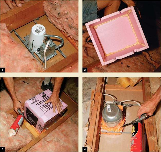
Recessed lights are one of the most overlooked sources of air leaks into attics. The best choice is to change old can bodies (1) for airtight insulation-contact-rated (IC-rated) models (see the photo at right) and then seal the rim to the drywall with foam or caulk. IC-rated lights that aren’t airtight can be sealed by covering the fixture with an airtight box made from rigid-foam insulation (2 and 3), metal, or drywall, or by sealing holes in the can body with spray-foam insulation (4).

Remember that non-IC-rated cans need an airspace around them and can’t come in contact with the insulation. Some sources recommend installing a sealed box over non-IC-rated cans, but recessed-light manufacturers frown on this practice.

Replace, Seal, or Enclose Recessed Lights

The best practice is to replace non-IC-rated cans with air-sealed IC-rated models.

Nail on the double top plate

In some parts of the country, carpenters raise the walls before cutting and nailing on the double top plate. In my opinion, the time to nail on the double top plate is now—while the wall is still flat on the floor. Otherwise, vou will have to use a ladder. The top plate is an important structural member. It ties the entire frame together. Without it, severe lateral stress from an earthquake or high winds could easily rip apart a building. If you frame with a single top plate, secure them together with metal plate straps.

On a 2×4 butt wall, the double top plate extends beyond I be top plate a bit less than 3k in. (cut it / in. short—about 3k in.—to make sure it doesn’t protrude beyond the
through wall), so that it can tie into the notch in the double top plate of a through wall.

On through walks, the double top plate has notches where it receives the double top plates extending from butt or intersecting walls.

Now you can see why it was important to mark the plates accurately while locating the corners and channels. You don’t need to mea­sure the length of double top plates. All you need to do is set the double top plate on a through wall above the top plate, with one end held back У/ in. (5k in. on 2×6 walls) from the end, then cut it to length.

Подпись: Helping HandПодпись: Remove all temporary nails. When prying loose wall plates and other parts that are temporarily tacked together, make sure you remove all "tacking" nails so that they don't cause injuries.Nail on the double top plateПодпись: CUT THE DOUBLE TOP PLATE. With the bottom plate nailed off, cut the double top plate in place, following the layout marks on the top plate.At channel marks, leave 3k-in. cutout so that an intersecting wall can comfortably lap over and tie in at that spot (see the photo on p. 98). When cutting and installing double top plates, leave about a 3k in. gap where the walls tie into each other. This makes it eas­ier for the overlapping double top plates to

Подпись: Helping HandПодпись: Alignment is important. As volunteers learn to nail studs, they often find it difficult to keep them aligned on their layout marks and to keep their edges flush with the edges of wall plates. For more accurate results, work in teams of two. Have one volunteer hold the stud on its layout while another drives the nails. Use a cat's paw to pry studs and nails loose when the alignment must be corrected. Подпись:Nail on the double top plateslip into place. This is another one of those times when it’s okav to be less than absolutely
4 4

accurate.

When von nail the double top plate to the top plate, it’s important to make sure that there are no gaps in the top plate. The top plate stock must butt tightly together, just as it did when you plated the walls in step 2. Nail the double top plate to the top plate with two 16d nails at each end of the wall and at each break in either the top plate or the double top plate. Elsewhere, nail one 16d nail over each stud. It is best not to nail between studs, because electricians and plumbers run w res and pipes through holes drilled in those loca­tions. Hitting a nail while drilling can dull the bit and give your arm a nasty twist.

Gutter Hangers

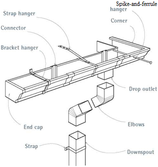
Gutter sections need to be supported by hang ers at least every 32 in.; closer if there’s a heavy snow or ice load. The many variations can be grouped into two general types: roof mounted, which employ a strap nailed to roof sheathing, and fascia mounted, which screw or nail directly to fascia boards or rafter tails. Whatever type hanger you use, gutters are less likely to pull free if you nail or screw the attachers to framing behind the fascia or roof sheathing. Here are profiles of four common hanger types:

► Spike-and-ferrule hangers nail directly into rafter ends or through fascia boards. Although this is a simple system, its detractors point out that 7-in. spikes leave large holes, encourage rot, and—in the end—don’t hold well.

► Roof-mounted strap nailers support gutters well and are an alternative to end-nailing rafters—in fact, they’re the only option when there’s no fascia. If you’re reroofing, nail them to the roof sheathing and apply shingles over them.

Or, if the rafter tails are exposed, nail the straps atop the rafters, and install flashing over the straps to forestall rot.

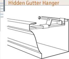
► Hidden hangers are favored for hanging K-style aluminum gutters. They can be inserted into the gutters on the ground and, thanks to integral screws, attached to the fascia one-handed. But because they clip inside the gutter channels— rather than supporting them underneath—these

image310

Hidden hangers are commonly used with К-type gutters. They can be prepositioned in the gstter and quickly screwed or nailed to the faseia. Because hangers are not visible, gutter lines are clean.

hangers are best used with heavier, 0.032-in. gutter stock, which is stiffer and less likely to flex or sag than the lighter stock.

Подпись: Prefab Gutter Pieces Подпись: Spike-and-ferrule Подпись: Prefabricated gutter pieces facilitate assembly. Use the hanger type most appropriate to your eaves detailing. ► Bracket hangers are usually lag screwed to fascia boards. They range from plain 4-in. brackets that snap over the back gutter lips to cast bronze brackets ornamented with mythical sea creatures. Brackets simplify installation because you can mount them beforehand—snap a chalkline to align them—and then set gutters into them.

Some Typical Loads, in Pounds per Square Foot (PSF)

Подпись: Attic, where finished rooms are not a possibility = Bedrooms = Living areas = Snow load — variable — ask local building inspector = Fully saturated earth (10 PSF per inch of thickness, thus 8 inches = 80 PSF) = Crushed stone: Same as saturated earth (10 PSF) = Conventional roof framing with roofing and insulation = Heavy timber framework, roofing and insulation for an earth roof =

Note: this is the dead load. With conventional (non­earth) roofing, the dead load is included in the rafter span tables. Thus, if you are looking at a table for rafters for a zone of 70-pound snow load, the

20 PSF 30 PSF 40 PSF 10 to 100 PSF 10 PSF per inch 10 PSF per inch 7-10 PSF* About 15 PSF*

dead load is also factored into the table. With heavy frames, such as for earth roof construction, it is better to add the dead load to everything else.