Sampling of Groundwater

Groundwater sampling can be performed in existing facilities (wells, piezometers, springs, etc.) or in new ones that need to be built. In this latter case, it is more frequent to install piezometers of a small diameter, just enough to be compatible with the monitoring equipment to be subsequently used. Most groundwater sam­pling installations must be located downgradient to the road discharges in terms of the local groundwater flow if they are to look for road-induced contamination. A few upstream locations may also be chosen to allow a reference water condition to be established. Their depth should be at least 2-3 m below the minimum annual groundwater level in order to avoid having a dry piezometer. The necessary number of piezometers depends on the dynamics of groundwater (i. e. varying condition with time and place) (Leitao, 2003). Higher permeability and hydraulic gradient implies monitoring in more locations and more frequently.

To obtain a sample that is representative of the water in the well or piezometer in question, there should be a purging operation until electrical conductivity, pH and temperature of the outflow water have stabilized (Aller et al., 1989). In low permeability soils the purging operation should try to minimize the water displaced during purging, otherwise recharge of the sampling location will take too long to allow realistic sampling. The water can then be sampled directly or using a device similar to Van Dorn’s water bottle, but with a size compatible with the well diameter (Fig. 7.6).

Classification of time-dependent reliability models

Repeated loadings on a hydrosystem are characterized by the time each load is applied and the behavior of time intervals between load applications. From a reliability theory viewpoint, the uncertainty about the loading and resistance variables may be classified into three categories: deterministic, random fixed, and random independent (Kapur and Lamberson, 1977). For the deterministic category, the loadings assume values that are exactly known a priori. For the random-fixed case, the randomness of loadings varies in time in a known man­ner. For the random-independent case, the loading is not only random, but the successive values assumed by the loading are statistically independent.

Deterministic. A variable that is deterministic can be quantified as a constant without uncertainty. A system with deterministic resistance and load implies that the behavior of the system is completely controllable, which is an ideal­ized case. However, in some situations, a random variable can be treated as deterministic if its uncertainty is small and can be ignored.

Random fixed. A random-fixed variable is one whose initial condition is random in nature, and after its realization, the variable value is a known function of time. This can be expressed as

Xt = X0 g(T) for t > 0 (4.95)

where X0 and Xt are, respectively, the random variable X at times t = 0 and t = t, and g(T) is a known function involving time. Although Xt is a random variable, its PDF, however, is completely dependent on that of X0. Therefore, once the value of the random initial condition X0 is realized or observed, the value of subsequent time can be uniquely determined. For this case, given the PDF of X0, the PDF and statistical moments of Xt can be obtained easily. For instance, the mean and variance of Xt can be obtained, in terms of those of X0, as

E(Xt) = E(X0)g(t) for t > 0 (4.96a)

Var(Xt) = Var(X0)g2(t) for t > 0 (4.96b)

in which E(X0) and E(Xt) are the means of X0 and Xt, respectively, andVar(X0) and Var(Xt) are the variances of X0 and Xt, respectively.

Random independent. A random-independent variable, unlike the random-fixed variable, whose values occurred at different times are not only random but also independent each other. There is no known relationship between the values of X0 and Xt.

AND GROUND FAULTS

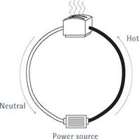
Electricity moves in a circle from power source back to power source, whether it travels across the country in great transmission lines or flows through the cables in your walls. In a house, each distinct electrical loop is called a circuit.

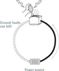
Most of the time, household electricity flows through copper wires (low resistance) insulated with thermoplastic or rubber (very high resist­ance). But electrical current is opportunistic. Should a wire’s insulation break and a fault cir­cuit of lesser resistance become available, current will flow through it. The current flowing through that fault circuit is called a ground fault. The lower the fault circuit’s resistance, the greater that current flow will be.

If equipment and appliances are correctly grounded (bonded together), this abnormally high current flow (amperage) will trip a breaker or blow a fuse, cutting power to the fault circuit—or "clearing the fault,” as electricians say.

ELECTRICITY IN THE HOUSE

A modern electrical system consists of three large cables, or conductors, which may enter the house overhead or underground. When fed underground, service conductors are installed in buried conduit or run as USE (underground service entrance) cable. Overhead service run­ning from a utility pole typically consists of a triplex assembly—two insulated hot conductors wrapped around a bare messenger cable that also serves to carry the neutral load—which runs to a weather head atop a length of rigid

PLAY IT Safe

Only a licensed electrician should work in a service panel—or remove its cover. Even with the main fuse or breaker turned off, some of the cables inside a panel are always hot (carry­ing electricity) and could electrocute you.

So could hot wires touching the sides of an incorrectly wired panel. Don’t mess with electric meters, either: Call the utility company to install meters or upgrade incoming service.

Подпись:Подпись: WIRES, CABLES, AND COPdUCtOrS The terms wires, cables, and conductors are often used interchangeably, but they are not exactly the same. A conductor is anything that carries or conducts electricity. A wire is an individual conductor, and cable is usually an assembly of two or more wires, protected by a plastic or metal cable sheathing (also called a jacket). Often, cable derives its name from the size of the wires within. For example, 12-gauge cable contains 12AWG (American Wire Gauge) wire. More specifically, 12/2 with ground denotes cable with two 12AWG wires plus a ground wire. Подпись: Circuits and Ground Faultsimage463image464Подпись: Electricity tends to move in a circle (circuit) to and from a power source, flowing through insulated wire. Current flowing through an unintended conductor, such as a person, is called a ground fault. Because only a little current flowing through your heart can kill you, ground faults can be fatal.To work safely on existing circuits, always disconnect electrical power at the service panel, and use a voltage tester (see the photos on p. 235) at the outlet to verify that the power’s off. Throughout this chapter (and book), you’ll see this symbol as a reminder:

Подпись: A Service EntranceПодпись: N

AND GROUND FAULTS
Подпись: The main panel houses incoming cables from the meter, as well as the breakers and wires that distribute electricity to individual circuits. At the service, neutral conductors (white wires), equipment-grounding conductors (bare copper or green insulated wires), the metal service panel, and the grounding electrode system (grounding rods) must be bonded together.

conduit. (Overhead service cables are called a service drop.) Whether it arrives overhead or underground, three-wire service delivers 240 volts. An old service with only two incom­ing wires—one hot and one grounded neutral conductor—delivers only 120 volts, which is inadequate for modern household demand and so should be upgraded.

Service conductors attach to a meter base. From the meter base runs another length of rigid conduit, or service entrance (SE) cable, to the service panel. Straddling the two sets of terminals on its base, the meter measures the wattage of electricity as it is consumed. (Increasingly common are meter-main combos, which house a meter base and a main service panel in a single box.)

Main service panel. At the main service panel, the two hot cables from the meter base attach to
lug terminals atop the main breaker, and the incoming neutral cable attaches to the main lug of the neutral/ground bus, as shown in "Main Service Panel, Unwired,” below. In main service panels, neutral/ground buses must be bonded, usually by a main bonding jumper. Important:

In subpanels and all other locations down­stream from the main service panel, ground and neutral buses must be electrically isolated from each other.

In a service fuse box, the hot cables attach to the main power lugs, and the neutral cable to the main neutral lug. Whether the panel has breakers or fuses, metal buses issue from the bottom of the main breaker/main fuse. Running down the middle of the panel, buses distribute power to the various branch circuits. Similarly, neutral/ground buses are long aluminum strips with many screws that ground and neutral wires attach to.

Подпись:image467THE Main BREAKER

All electricity entering a house goes through the main breaker, which is usually located at the top of a main panel. In an emergency, throw the main breaker switch to cut all power to the house.

The main breaker is also the primary overcurrent protection for the electrical system and is rated accordingly. (The rating is stamped on the breaker handle.) Thus if the main breaker for a 200-amp panel senses incoming current that exceeds its overload rating, the breaker will automatically trip and shut off all power.

Each fuse or breaker is rated at a specific num­ber of amperes (amp), such as 15 or 20. When a circuit becomes overloaded, its current flow becomes excessively high, causing its breaker to trip or its fuse strip to melt, thereby cutting volt­age to the hot wires. All current produces heat, but as current doubles, the heat generated quadruples. If there were no breakers or fuses, current would continue flowing till wires overheated and a fire started. Thus the amperage ratings of breakers and fuses are matched to the size (cross-sectional area) of the circuit wires.

Branch circuits. Branch circuits are conductors that run from the last overcurrent device (fuse or breaker) to their outlets. Inside each cable or conduit are several wires color-coded for safety.

In most 120-volt circuits, there is one hot wire (coded black), one neutral wire (coded white), and one bare copper (or green) ground wire. Think of hot and neutral wires as parallel wires that must never be joined.

Ground wires (discussed later in this chapter) must also be kept separate from hot and neutral wires as you run branch circuits. (Ground and neutral bus bars are connected in the main panel, but that’s another issue.) In 240-volt circuits, such as those “dedicated” to a heavy user like a stove, there are typically two hot wires: one coded black, and the other, red.

Outlets. Each branch circuit serves one or more outlets. At outlets, individual wires connect to various devices such as switches, receptacles, and fixtures. To ensure a safe hookup, the devices’ connecting screws or terminals are color coded or otherwise clearly designated: Hot wires attach to gold – or brass-colored screws, neutral wires to silver screws, and ground wires to green screws (when present).

Switches cut or vary the flow of power by inter­rupting hot lines only. Neutral wires are always
continuous, as are ground wires, even though their sections may be connected by wire nuts. Wire nuts are insulated caps that twist onto the bare ends of wire splices (clusters), thereby joining them mechanically and covering them so those bare ends can’t come in contact with other wires, devices, fixture terminals, or the outlet box itself.

THE GROUNDING SYSTEM

A house’s grounding system is complex, and understanding it is made more difficult by the imprecise language used to describe it—as noted in “Making Sense of Grounding,” on p. 230. If you want a more comprehensive overview of grounding, get a copy of the book Code Check® Electrical, mentioned earlier. Here are some of the basics.

Underlying principles. Fuses were among the earliest overcurrent devices, and they greatly reduced the incidence of electrical fires by dis­connecting current when its flow became too great. But something more was needed to protect people, who were being electrocuted when they came in contact with fault currents unintention­ally energizing the metal casing of a tool or an electrical appliance, for example.

Подпись: PROTIP It's advisable to ground metal water piping in case it becomes energized, but don't rely on metal water pipes instead of grounding electrodes. Otherwise, someone could disconnect the pipe or install a section of non-conductive pipe such as PVC, thus interrupting the grounding continuity and jeopardizing your safety. In new installations, code requires that metal water piping be connected to the electrode system and supplemented with another electrode. Подпись: 1111Подпись:Consequently, the industry added equipment­grounding conductors (which we’ll call ground wires) that bond all electrical devices and poten­tially current-carrying metal surfaces. This bond­ing creates a path with such low impedance (resistance) that fault currents zip along it as they return to the power source—quickly tripping breakers or fuses, and clearing the fault. Contrary to popular misconceptions, the human body has a relatively high impedance (compared to copper wire), so if electricity is offered a path of less resistance (a copper ground wire), it will take it.

To sum up: To reduce shock hazards, individ­ual ground wires connect to every part of the electrical system that could become a potential conductor—metal boxes, receptacles, fixtures— and, through three-pronged plugs, the metallic covers and frames of tools and appliances. At the main service panel, these ground wires attach to a neutral/ground bus bar, which is itself bonded to the metal panel via a main bonding jumper.

To quote one master electrician, "This bonding jumper is possibly the most important single con­nection in the whole system.”

Grounding electrode system. Also attached to the neutral/ground bus in the service panel is a large, bare copper ground wire —the grounding electrode conductor (GEC)—that clamps to a grounding electrode (also called a ground rod), which is driven into the earth or is attached to steel rebar in the footing of a foundation. The electrode’s primary function is to divert lightning
and other outside high voltages before they can damage the building’s electrical system.

Note: Although the grounding electrode system (GES) is connected to the equipment­grounding system at the service panel, the GES has virtually nothing to do with reducing shock hazards.

The NEC sizes grounding electrode conduc­tors based on the sizes and types of conductors in the service. Typically, residential GECs are size 6 American Wire Gauge (6AWG) copper. Ground rods are typically 58-in. to 54-in. copper-clad steel rods 8 ft. to 10 ft. long; the longer the rod, the more likely it will reach moist soil, whose resist­ance is less than that of dry soil. Be sure to install multiple-rod systems in lightning-prone areas.

GROUND-FAULT CIRCUIT INTERRUPTERS

Despite the presence of grounding systems, peo­ple were still being killed by electrical shock, particularly when moisture was present. To rem­edy this problem, the industry developed ground-fault circuit interrupters (GFCIs), which are highly sensitive devices that can detect minuscule current leaks and shut off power almost instantaneously. A ground fault is any fail­ure of the electrical system that leaks current from a hot wire.

Normally, the current in hot and neutral wires is identical. But when there is as small a variance as 0.005 amp (5 milliamperes) between hot and neutral wires, a GFCI can shut off all power within 540 of a second. Consequently, the NEC now requires GFCI protection on all bathroom recep­tacles, kitchen receptacles within 4 ft. of a sink, all receptacles serving kitchen counters, all out­door receptacles, accessible basement or garage receptacles, and receptacles near pools, hot tubs, and the like.

A GFCI breaker will cut all power to a circuit, whereas a GFCI receptacle will cut power to receptacles downstream if wires are fed through the GFCI receptacle as shown in "Wiring a GFCI Receptacle,” on p. 250.

ARC-FAULT

CIRCUIT INTERRUPTERS

When electrical connections are loose or corrod­ed or if nails puncture wires, electricity can arc (jump) between points. Arcing may be respon­sible for many of the 40,000 electrical fires each year. The NEC now requires arc-fault circuit interrupter (AFCI) protection for all 15-amp and 20-amp bedroom circuits. Just as GFCIs cut power to prevent shocks, AFCIs detect minute fluctuations in current associated with arcing
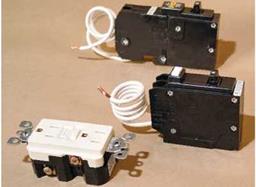
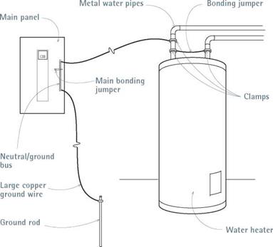
image468image469Подпись: The equipment-grounding system acts as an expressway for stray current. By bonding conductors or potential conductors, the system provides a low-resistance path for fault currents. The abnormally high amperage (current flow) that results trips a breaker or blows a fuse, disconnecting power to the circuit.Electrical safety devices. From fop:arc-fault circuit interrupter (AFCI) breaker, ground-fault circuit interrupter (GFCI) breaker, and GFCI receptacle.

and de-energize the circuits before a fire can start. Installing AFCI breakers is essentially the same as that for GFCI circuit breakers.

A Radon-Control Retrofit

John Banta was called to evaluate a home for radon. The owner had received a do-it-yourself radon test kit as a gift from relatives. When he fi­nally got around to performing the test, he could not believe the laboratory results. His daughter’s room registered 24 picocuries, six times higher than the EPA’s recommended action level. John’s electronic radon equipment confirmed the test results.

John proposed a radon reduction technique called subslab suction. It involved sucking radon from under the slab and ventilating it to the out­side. Holes would be drilled in the downstairs slab so that pipes could be inserted and connected to an exhaust fan, a method frequently used in unfinished basements. Since the owner had just finished installing an expensive marble floor downstairs, he was not willing to accept this pro­posal.

After some thought, John suggested that the subslab suction technique be modified so that the drilling would take place horizontally under the slab through the outside of the hill on which the first floor rested. A company that drills horizon­tal wells was contracted for the job. The site was surveyed and the drill set to bore just under the foundation. Six evenly spaced holes were bored horizontally all the way under the house. After the drill was withdrawn from each hole, a perforated pipe was inserted to provide a pathway for gas from radon-contaminated soil to be sucked from under the home. The owner finished the job by

aggregate through the center of the envelope. The pipe is connected to an unperforated riser tube that vents to the outside. The vent tube acts as a passive radon removal outlet.

If radon levels are still unacceptable once the building is completed, a fan can be attached to the vent pipe to actively suction out the gas.

Method 2: In place of aggregate and per­forated pipe, Soil Gas Collector Matting can be laid on the finished grade prior to pour­ing concrete. The matting, which is covered in filter fabric, is laid around the inside pe­rimeter of the foundation in a swath about one foot wide, and the concrete is poured di­rectly on top. The matting is connected to a vertical riser vent that extends through the roof. The natural chimney effect will draw the soil gas upward. If deemed necessary, the system can be adapted for active suction with the addition of a fan once the building is enclosed. In areas with high water tables, consult a geotechnical engineer about proper drainage prior to installing any soil gas re­moval system.

Products for Soil Gas Control

The following low-emission products may be used to block entry of radon from the ground into the living space:

• AFM Safecoat DynoSeal: Water-, vapor-, and moisture-proof membrane sealer

• Cross Tuff: Specify radon-control grade

• Tu-Tuf4: Crosslinked polyethylene sheet­ing

Water Management at Doors and Windows

Door and window openings that are improp – joining all the perforated pipes together with solid pipe. At a short distance from the home he con­nected an exhaust fan to the pipe to suck radon to the outside, where it dissipated. The pipes were then covered with soil and the area landscaped. The radon in the home was reduced to an accept­able level of approximately one picocurie. If the fan is shut off, however, the radon level will begin to climb. More radon testing was carried out on other buildings located on the property and in the general neighborhood. No other elevated radon levels were found.

Discussion

Radon can exist in isolated spots, depending on underlying geological formations. Some parts of

erly detailed are a common source of water intrusion in homes. Often these leaks go un­detected until they have caused severe damage when water finds a path directly into the wall cavity without ever revealing damp surfaces visible from within the home.

Until recently, all products for door and window flashing were asphalt-based. The fol­lowing flexible flashing products do not con­tain asphalt:

• Tyvek Flex Wrap: Self-sealing, 70-mil elas – ticized polyethylene film laminate with a synthetic rubber adhesive for windowsills, round top and custom shaped windows, 3D sill projections, and wall interruptions

• Tyvek StraightFlash: Self-sealing, 30-mil polyethylene film laminate with a syn­thetic rubber adhesive for jambs and heads of rectangular shaped windows

the US are known to have higher radon levels than others. Homes with basements, cellars, or other subterranean structures are the most susceptible to radon accumulation. Yet even homes with slab foundations and ventilated crawl spaces can have elevated levels. The only way to be certain is through radon testing. In John’s experience, radon can almost always be reduced to accept­able levels. When building your home, use appro­priate techniques to avoid the possibility of radon accumulation if radon is known to be present in your area.

• VaproFlashing: Non-self-sealing bonded polypropylene fabric flashing, requiring the use of VaproAdhesive to adhere to most building materials (refer to Vapro- Shield)

• WindowWrap-Butyl: Self-sealing 20-mil laminated polyethylene film with butyl rubber adhesive for flashing window and door openings and building joints

Control according to U. S. Documents

The distinctive feature of the contemporary U. S. approach to production control is the application of statistical methods and fines as punishment for exceeding admis­sible limits or deviations from the mix design. (Sometimes bonuses, or incentives, are also used to reward exceptional production consistency, but penalties are more common.)

The quality control methods widely employed in the United States are called quality control/quality assurance (QC/QA). These systems typically involve test­ing recently produced bituminous mixtures for the following (USACE Handbook, 2000):

• Mix components—binder content and gradation of the mineral aggregate

• Physical properties of the mixture measured on compacted Marshall or gyratory samples

• Air-void content

• VMA

• Voids filled with binder (VFB)

• Density

• Stability and flow, if required

Under QC/QA specifications, the mixture manufacturer is charged with the respon­sibility for quality production control (QC). Its laboratory’s duty is to undertake con­trol activities. Verifying the operation of QC, or QA, is the investor’s (or owner’s) responsibility. It is necessary to stress again that in the United States sliding scales of fines are imposed, depending on the statistical results of production control.

Every producer of a mixture must formulate and submit for approval a quality con­trol plan (QC plan). Broadly speaking, this type of plan[59] comprises such details as the determined features under control and the frequency of their testing, the methods for recording results, and the corrective actions taken in case of excessive deviations from a formula. Additionally, the QC plan outlines the number and the frequency of equipment inspections, the calibration of instruments, and document management. More information on control using QC/QA specifications may be found in various U. S. publications (The Asphalt Handbook, 1989; USACE Handbook, 2000).

CULVERT SERVICE LIFE

The prediction of service life of drainage facilities is difficult because of the wide range of environments encountered and the various protective measures available. Service life and durability are directly related to resistance to corrosion, abrasion, and other modes of deterioration.

5.7.1 Design Service Life

Drainage facilities are usually designed for a specific service life. The design service life is sometimes defined as the expected period for which they are relatively free from maintenance. However, it can be defined to include a planned rehabilitation after a given number of years to reach the required service life as part of a value analysis approach. (See Art. 10.10.1.)

For a metal culvert, the design service life can be based on the number of years between the time it is installed and the time a perforation from either corrosion or abrasion occurs at any location in the culvert. However, this is a rather conservative approach because the consequences of small perforations are usually minimal and a single perforation can occur long before there is a general thinning of the metal. Thus, service life charts are often based on an average service life that extends life past first perforation by 25 percent or more. For a concrete culvert, the design service life is usually defined as the time between installation and when deterioration reaches the point of exposed reinforcement anywhere in the culvert.

The selection of design service life is dependent upon the use, importance, and ease of replacement of the culvert. A culvert located under a high fill or a roadway with high traffic volumes will be expensive to replace, and the replacement will disrupt traffic. Thus, such culverts are often assigned a design service life of 50 years or more. In contrast, a culvert parallel to the main road—for example, a pipe underneath an access road—will be relatively easy to replace and can be replaced with little disruption. Thus, such culverts, including those under low fill or on a minor roadway, are often assigned a shorter service life.

Sampling from Surface Water Bodies

Water samples should be collected from surface water bodies (lakes, rivers, streams, ponds, etc.), taking into account the velocity field in flowing water and any possible stratification in standing water. Once the location and frequency of water sampling are selected there are a set of procedures for sampling water in the natural environ­ment (from surface water bodies) that need to be considered. Figures 7.4 and 7.5 give two examples of bottles for surface water sampling.

1. Ballast

2. Sample container

3. Supporting mesh

4. Rubber stopper

5. Suspension cable

6. Connecting cable

7. Air vent

8. Inlet

9. Vent and inlet caps

The bottle is unsealed at the sampling depth

1. Sample chamber

2. 8 3. Rubber end caps

4. Rubber pull-rod

5. Connecting and locking pin

6. Control mechanism

7. Sample outlet

The sampler is sealed by releasing the two end caps when the sampler is at the correct depth. The rubber pull-rod then contracts, pulling the end caps inwards so that the sampler is sealed at both ends

Sma mixture production control

The SMA mixture production process, like that of other asphalt mixtures, is subject to procedures to control its mixed components and other selected properties. These procedures differ among various countries, but in almost all cases, the control of gradation and binder content form their common root.

The control of the production process mostly consists of periodically check­ing the components of the produced mixture in relation to the approved labora­tory recipe. Generally, two methods applied world wide may be distinguished as follows:

• The control of the aggregate gradation on selected sieves and the content of soluble binder within given tolerances of production accuracy

• The control of SMA volume properties (e. g., the content of voids in a min­eral aggregate (VMA) and the content of voids in a compacted asphalt mixture)

It is good to emphasize the control of the volumetric properties during the pro­duction process; it is even more logical to verify the volume ratios determined at the design stage during production. Furthermore, control of the aggregate gradation alone, within allowable tolerances, does not guarantee the correct volume ratio of coarse aggregates, mastic, and air voids.

9.5.1 Control according to the German Document ZTV Asphalt-StB 07

The quality of the produced mixture may be determined by ZTV Asphalt-StB 07. The following tests are included in the scope of methodical control activities (Table 26 ZTV Asphalt-StB 07):

• Gradation on selected sieves

• Soluble binder content

• R&B softening point of the recovered binder

• Bulk density and air-void content in compacted Marshall samples

The factory production control (FPC) organization and the whole verification of a conformity system[58] 2 + is in accordance with requirements contained within the European Standard EN 13108-21.

Seal twice around vents

The vent pipes that extend through the roof are flashed with special rubber or metal boots when the shingles are installed. But here in rainy Oregon, roofers take the time to make a double seal around these pipes. This is sort of like wearing a slicker and carrying an um­brella, too—but there’s no such thing as being too careful when it comes to roofs and water.

To provide this extra protection, cut a 3-ft.-sq. piece of felt and cut a hole in the center the size of the vent pipe. Slip the felt over the vent and seal around the pipe with a tube of roofing tar. Do the same when you roll out the long strips of roofing felt. Cut the second layer of felt around each vent and again seal it around the pipe with roofing tar. You can lap the felt over the ridge, but remember to cut it away when you shingle to permit airflow into the ridge vent.

Protect valleys and intersections

When a porch roof intersects the main roof at a right angle, valleys are created on each side of

the intersection. Valleys divert more water than a regular gable roof does, so I always provide extra protection in the form of flashing. I like to roll at least two layers of 30-lb. felt right down the center of the valley. Even better is to cover the valley area with a sheet of 90-lb. rolled roof­ing. Then, when you install regular roofing felt, lay each row 12 in. or more beyond the valley and keep all roofing tacks at least 12 in. from the center of the valley. This technique provides a double layer of protection prior to shingling.

When working on a roof that butts into the sidewall of a house (a porch roof connected to a gable end, for example), lap the felt on the sidewall by at least 6 in. to prevent leaks at the intersection.

Install a drip edge

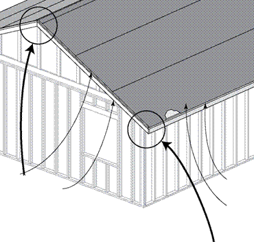
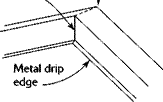
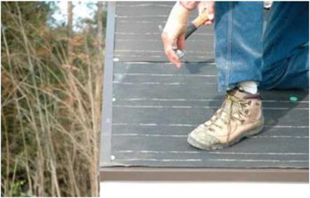
Once the felt is in place, make it more secure around the edges by installing sections of vinyl or metal drip edge. Drip edge is an L-shaped metal or vinyl flashing that comes in 10-ft. sections. One leg of the L profile extends about ІУ2 in. up the roof; the other leg extends down the fascia or barge rafter by the same distance (see the photo at right). It has a slight lip on the lower edge to divert water from the roof.

Using roofing nails, install the drip edge under the felt at the eaves and on top of the felt at the rakes, or gable ends. Space nails about 2 ft. apart. Where one length of edging joins another, overlap the joint by about 4 in. Along the gable ends, make sure the top length of the drip edge laps over the one below. At the corners, cut a pie-shaped slice out of the top section. This allows you to bend the drip edge at a 90-degree angle and nail it around the corner. At the ridge, make a plumb cut in the vertical leg and bend the edge over the ridge, allowing the plumb cut to overlap, as shown in the illustration above.

Подпись: III III III III III III II III III III III III III III II III III III III III III III III II III III III III III III III III II III III III III III III III III II III III III III III III III III II III III III III III III CUTTING AND INSTALLING A DRIP EDGE Подпись: Drip edge on top of paper Cut the face of the metal. Подпись:Подпись:Подпись:Подпись:Подпись:Seal twice around ventsSeal twice around ventsSeal twice around ventsПодпись: The metal drip edge is placed on the fascia or gutter boards and barge rafters before shingles are nailed to the roof.Подпись: Metal drip edge Seal twice around ventsInstalling a drip edge. This L-profile flashing is installed to protect the edges of the roof. The bot­tom flashing goes beneath the paper and the side flashings go on top. [Photo by Don Charles Blom]
STEP 9 SHINGLE THE ROOF

Nail buggy

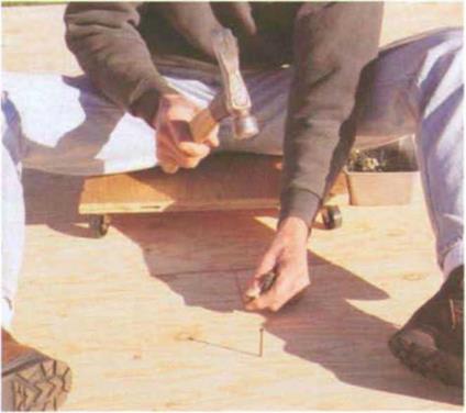
Подпись: Sitting on a nail buggy makes it easier to nail floor sheathing. (Photo by Roe A. Osborn.)Nail buggyA nail buggy is a good tool when you have to nail subfloor by hand. Better to nail sitting on your bot­tom than crawling on your knees. Cut a 20-in. circle or square from 3A-in. plywood. Buy three or four good wheels at least 2 in. in diameter and screw them to the bottom of the plywood. Attach a bread pan to the side to hold nails. Now, like an Olympic swimmer doing laps, you can sit on the buggy and push yourself backward as you nail down subfloor. Just don’t roll off the edge of the floor.
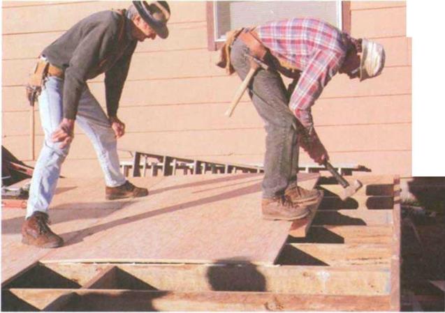
Подпись: Sometimes T&G plywood needs some not-so-gentle persuasion. Have one person stand on the sheet to hold it flat and snug against the previous row while another hits it with a sledgehammer. The 2x placed in front of the sheet protects the plywood edge from damage. (Photo by Roe A. Osborn.)Nail buggy

from damage) and hits it with a sledge­hammer (see the photo at right). A couple of licks should bring the two sheets together.

Once you have all the sheets tacked in place, you can move around the floor driving nails to secure the sheathing to the joists firmly. (A nail buggy will make this job easier; see the sidebar above.)

A typical nailing schedule would be to drive 8d nails 4 in. o. c. on the perimeter (around the outside), б in. o. c. near joints, and 12 in. o. c. in the field (in the middle of the sheets). You may want to use ring-shank nails for better holding power.

Drive the nails straight into the center of the joists. While some carpenters snap a chalkline as a nailing guide across each sheet, try nailing by eye. When you feel that you have missed a joist, stop, pull the nail, and drive another.