Transport

The main objective of transporting a mixture from the asphalt plant to the laydown site is to deliver the mix without changing its properties and in a state that allows for appropriate placement and compaction. Minimizing heat loss and preventing seg­regation of the mixture constituents are two of the most important issues regarding transportation. Requirements for transporting the mixture to the work site are often defined in technical specifications. Typical requirements are shown, as examples, in the following:

• Specified maximum distance between the asphalt plant and laydown site (e. g., 40 km)

• Maximum travel time from the asphalt plant to the work site (e. g., 2 hours)

Specifying the distance between the asphalt plant and the construction site can be quite a misleading operation since traveling a distance of 40 km in a rural area does not take the same amount of time as driving the same distance in a large city. Driving time is the more accurate requirement; however, some differences may be noted even in that. Mix will not cool as much after 2 hours during the sum­mer as it will after the same amount of time in the late autumn. Probably the best way of setting the requirements for transportation is to establish temperature con­ditions for the mixture. This method of specifying requirements may be found in the European standards concerning bituminous mixtures (e. g., in EN 13108-5 [the European standard on SMA]). There are maximum production temperatures speci­fied for various types of bituminous binders and a minimum supply temperature for the delivered mixture. One should meet that temperature range when planning the production and transport of a mixture to a work site, taking into account such factors as the prevailing weather conditions, and the location of the asphalt plant. This is definitely the more common solution.

When transporting hot SMA, a crust of cooler mixture is formed on its surface. The higher the degree of cooling of the mixture, the thicker the crust, and the more problems it causes. As long as the mixture is well-protected thermally (by a tarp or insulation), the layer of cooler mixture will be thin and the chance to intermix it with the rest of the material during laydown will remain high. Significant cooling of the
mixture during transportation or while waiting for discharge leads to the build-up of a pretty thick crust. Large pieces of cool, unmixed material cause a nonuniform texture in a laid-down course (for details see Chapter 11). In that case, good mixing may be provided by a buffer like a material transfer vehicle (MTV) or Shuttle Buggy (Brown, 2002) (see Section 10.1.4).

There is an analysis concerning the heat losses of an asphalt mix during site transportation in the paper by Spuziak (2002). The analysis assumes that heat losses during mixture transportation may range from 5°C/hr (with good insula­tion) up to 48°C/hr (in exposed locations). The drop in the mixture temperature depends on the following:

• Weather conditions during transportation, including the air temperature, humidity, and wind velocity

• Air streamline speed (the speed of the truck loaded with mixture)

• Time of the mixture haulage

• Mass of the load

• Shape of the truck bed and its insulation properties

Concerning weather conditions, wind velocity is a decisive factor in the rate of cooling of the mixture during transportation. The mass, volume, and shape of the hauled material is also of great significance. Any reduction in the thickness of the transported layer of mixture induces quicker cooling, hence the shape of the truck bed is also of considerable importance. Taking this into account, beds with rounded or wedged edges are ideal (Figure 10.1) (Ulmgren, 2000, Spuziak, 2002).

image91 image92

In cool weather, the best way to retain the mixture temperature is to use an appro­priate means of transport. Trucks with insulated beds are the best solution, then the effect of the reduction of heat waste is perfectly obvious (Figures 10.2 and 10.3). In the case of such a truck being unavailable, tight and well-fitting tarps on trucks should be adopted as a minimum. Minimizing drops in the temperatures of SMA mixtures containing polymer modified binder (PMB) is particularly important.

FIGURE 10.1 Location of cooled spots of a mixture on a cross section of a truck bed (a) and (b). Truck bed shape prevents cold corners (c) and (d). (From Spuziak, W., Proceedings of the 6th International Conference Durable and Safe Road Pavements, Kielce, Poland, 2000. With permission.)

image93

FIGURE 10.2 The drop in temperature of mixtures with and without insulation over given periods. In these scenarios, the ambient temperature is —10°C, 0°C, or + 5°C; the bulk mix­ture is hauled in the truck bed or in a special insulated container; and the mixture temperature at the plant is either 140°C or 160°C. (From Spuziak, W., Proceedings of the 6th International Conference Durable and Safe Road Pavements, Kielce, Poland, 2000. With permission.)

10.1.3 Discharging

The suitable discharge of a mixture from a truck to the paver hopper helps to avoid some problems. The dump truck with the mixture should pull in directly in front of the paver to allow for the following:

• The truck to be positioned exactly on its motion axis, enabling the push roll­ers on the paver to contact both rear wheels of the truck.

• The truck can avoid bumping into the paver; bumping the paver can cause a bump in the pavement.

As a general rule, the paver should approach the truck and not the other way round (then the paver can push the dump truck without bumping).

Planning and Estimating

The scope of a renovation is always a trade-off between what you’d like and what you can afford. Oversizing the system slightly to accommodate future needs is usually money well spent.

Assess the existing system, see what local codes require, calculate future needs, and then map out an upgrade.

ASSESSING THE PRESENT SYSTEM

To assess the situation, start with two questions: Is the electrical system safe? and Is it adequately sized?

Is it safe? Hire a licensed electrician or a qual­ified home inspector to assess the electrical system and advise you about what needs doing. But before the electrician shows up, do a little hands-off looking for yourself and try to answer the following questions:

► Is the entrance panel grounded? There should be a large grounding wire running from the panel and clamped to a cold-water pipe and/or a grounding rod.

► Is there equipment grounding? Grounding the panel is not enough. For the entire electrical system to be grounded, there must be continuous ground wires running to every device in the house. If there is only two-wire service to the house and you see only two-hole receptacles in use, the system is outdated and has no equipment grounding.

► Do bathrooms, kitchens, garages, and outdoor outlets have GFCI receptacles, as required by the NEC?

I Major Grounding Elements

► Is the equipment in good shape? Rusty entrance panels, receptacles encrusted with paint, and wires with cracked or frayed insulation are as unsafe as they are unsightly.

► Is the service panel installed in a wet or damp area? This situation is extremely unsafe. In fact, many electricians refuse to examine service panels if there’s standing water nearby.

► Is present usage safe? Installing fuses too big for a circuit to prevent blown fuses is a fool’s bargain, as are overloaded receptacles, extension cords under carpets, and the like.

Is it adequate? If you’ve lived in the house for a while, you’ll have a fair idea of whether the sys­tem is big enough.

► Are there enough outlets, or do receptacles teem with multiplug and extension cords? If so, plan to add more receptacles where needed.

► Do you blow fuses often, especially when starting up small appliances or power tools? Does your TV screen shrink momentarily when the refrigerator motor or the water

Подпись: Calculating Total Electrical Load

General-use circuits:

_____________ sq. ft. x 3 volt-amp/sq. ft.

Small-appliance circuits:

_____________ 20-amp circuits x 1,500 volt-amp

Laundry circuit

(1,500 volt-amp each)

pump kicks in? These symptoms may indicate a system that’s close to its present limits.

► How many cables run from the utility pole to the house? If there are only two large cables, the electrical service is probably inade­quate. As explained in"Electricity in the House,” on p. 227, a two-wire service delivers only 120-volt service; whereas a three-wire service delivers 120-volt and 240-volt service.

► What is the panel rating on the name­plate? If there’s a two-wire service, the panel is probably rated for 30 amps. These days, a 100-amp entrance panel is considered minimal; a 200-amp panel can accommodate future uses.

Подпись: Major appliances/dedicated circuitsGENERAL CODE REQUIREMENTS

Water heater

Cooktop/oven or range ___________________

Garbage disposal ___________________

Dishwasher ___________________

Microwave ___________________

Other ___________________

Subtotal for all major appliances *

Note: volt-amp (volt-amperes) = volts x amperes. Asterisks (*) indicate subtotals for distinct groups.

Add the asterisked subtotals of each circuit group. Then multiply any volt-amperes greater than 10,000 by 0.40 (because not all outlets are drawing energy at the same time).

Подпись: Total volt-amperes: 10,000 volt-amp x 0.40 = (A) Add subtotal A to 10,000 volt-amp + 10,000 (B) Subtotal C = (C) To subtotal C add the volt-amperage of the heating system or the air-conditioner, whichever is greater: + (D) Подпись: Total volt-amperes = To convert this total volt-amperes to amperes, divide by volts: volt-amp-^240 volts = amp Подпись: Using This Table To determine the total capacity you need, add up the volt-amperes of (1) general-use circuits, (2) small-appliance circuits, (3) laundry circuit, and (4) major-appliance/dedicated circuits. Calculate the volt-amperes of general-use circuits first, by determining the square footage of the house; measure outside dimensions and include the areas of all finished living space. Then multiply the area in square feet by 3 volt-amp to obtain general-use volt-amperes. Assign small-appliance and laundry circuits 1,500 volt-amp each. All major appliance nameplates list amperage ratings.

Licensed electricians use NEC (National Electrical Code) formulas to size a house’s electri­cal load. Here’s an overview of NEC requirements.

General purpose.

► Keep lighting and appliance circuits separate. Calculate lighting loads at 3 watts per square foot, or roughly one 15-amp circuit for every 500 sq. ft. of floor space. When laying out the lighting circuits, do not put all the lights on a floor on one circuit. Otherwise, should a breaker trip, that entire floor would be without power.

► General-use circuits are intended primarily for lighting, but small users such as TVs, record players, and vacuums are allowed, as long they don’t exceed the capacity of the circuit. Though 14AWG wire is sufficient for lighting and switch runs, electricians often run 12AWG wire on general-use circuits to accommodate future uses.

► There must be a receptacle within 6 ft. of each doorway, and no space along a wall in a habitable room should be more than 6 ft. from a receptacle. Any wall at least 2 ft. wide must have a receptacle; and a receptacle is required in hallway walls 10 ft. or longer.

► The NEC does not specify a maximum number of outlets on a residential lighting or appliance circuit, though local jurisdictions may. Figure roughly 9 outlets per 15-amp circuit and 10 outlets per 20-amp circuit.

► There must be at least one wall switch that controls lighting in habitable rooms, the garage, and storage areas (including attic and basement). And there should be a switch near each outdoor entrance. Three-way switches are required at each end of corridors and at the top and bottom of stairs with six steps or more.

► All new 15-amp and 20-amp circuits in bedrooms must have AFCI breaker protection.

Kitchens and bathrooms.

► The NEC requires GFCI protection in the following locations: all bathroom receptacles; all receptacles serving kitchen counters;

all outdoor receptacles; accessible basement or garage receptacles; and receptacles near pools, hot tubs, and the like. (Check the current NEC for a complete listing.)

► Bathroom receptacle outlets must be supplied from a 20-amp, GFCI-protected circuit with no other outlets. However,

the NEC allows the circuit to supply required receptacles in more than one bathroom.

► There must be at least two 20-amp small-appliance circuits in the kitchen.

No point along a kitchen countertop should be more than 2 ft. from an outlet. Every counter at least 12 in. wide must have a receptacle.

► All critical-use stationary appliances must have their own dedicated (separate) circuits: water pump, freezer, refrigerator, oven, cooktop, microwave, furnace and/or whole-house air-conditioning unit, garbage disposal, window air-conditioners, and water heater.

► If a cable does not attach directly to an appliance, its receptacle must be within 6 ft. of the appliance.

CAN YOU ADD OUTLETS TO A CIRCUIT?

If there’s room in the service panel for additional breakers or fuses, adding circuits is largely a mat­ter of running cable and making good mechani­cal connections along the way. Have a licensed electrician connect new cable runs to the panel.

o To add outlets to a circuit, you must dis­connect the power from an existing outlet and fish new cable from it, as described on p. 261.

But first determine the load-bearing capacity of the circuit you want to extend.

Begin by identifying the circuit breaker (or fuse) controlling the circuit: (^) Turn off the elec­tricity to that circuit and test to be sure it’s off. Note the rating of the breaker. If it’s a general – purpose circuit, the breaker will probably be 15 amps or 20 amps. A circuit controlled by a 15-amp breaker has a capacity of 1,800 watts (15 amps x 120 volts); a 20-amp breaker,

2,400 watts. The total wattage of all energy users on the newly extended circuit must not exceed these capacities; otherwise, you risk overheating wires. To avoid overloading, load is calculated at 80 percent of capacity. For example, 80 percent
of 1,800 watts is 1,440 watts for a 15-amp circuit; 80 percent of 2,400 watts equals 1,920 watts for a 20-amp circuit. As a rule of thumb, 10 outlets is the maximum for a general-purpose or lighting circuit.

Safe Circuit Capacities*

VERTICAL LAYOUT FOR ROOF SHINGLES

To obtain the right layout, try this two-step method:

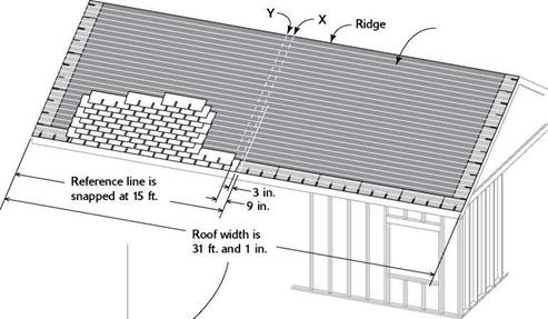
1. Measure across the roof from outside edge to outside edge (parallel with the eave wall), including the planned overhang distance for the shingles. For example, let’s assume that the shingles will overhang the drip edge by 1/2 in. Measure in yards (because the length of a standard shingle is 36 in.), plus remaining inches.

2 Measure in from the left edge by a round number of yards (say, 5 yd.) and mark that distance on the roof. Then refer to the chart below to ensure that all the shingles at the edges of the roof will be at least 15 in. wide (a full tab, plus 3 in.).

EXAMPLE. Let’s say the total distance across the roof, from gable end to gable end, is 10 yd. and 13 in. (including the 1/2-in. overhang at both ends). When you check the chart’s recommendations for a roof with a 13-in. remainder (12 in. to 15 in. is the range), you’ll see that the recommended offsets are 3 in. and 9 in.

From the reference mark at 5 yd., make marks 3 in. to the left and 9 in. to the left of the reference mark. You now have an offset of 6 in., or half the width of a shingle tab, between courses. Staggering the courses like this—so that the breaks between the tabs don’t stack up on top of each other—prevents water from seeping beneath the shingles.

Mlake the 3-in. and 9-in. offset marks at the bottom of the roof, near the eave, and at the top, near the ridge. Snap chalklines between the marks to establish your vertical start lines.

VERTICAL LAYOUT FOR ROOF SHINGLING


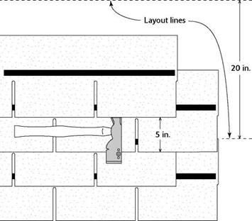
Horizontal lines are snapped 5 in. apart.


Layout Chart


Inches left over

X

Y

0" to 3"

15

21

3" to 6"

12

18

6" to 9"

9

15

9"to 12"

6

12

12"to 15"

3

9

15" to 18"

0

6

18" to 21"

3

9

21" to 24"

0

6

24" to 27"

3

9

27" to 30"

0

6

30" to 33"*

21

3

33" to 36"*

0

18

*X and Y lines are 18 in. apart, not 6 in.


A pair of vertical bond, or offset, lines are snapped near the center of the roof, 6 in. apart from each other and to the left of the reference line by the distances specified in the chart.


VERTICAL LAYOUT FOR ROOF SHINGLES

different reveals, so check the label for specifics.

Подпись: iiiїм їм їм їм їм и їм їм їм їм їм їм їм и їм їм їм їм їм їм їм їм и їм їм їм їм їм їм їм їм и їм їм їм їм їм їм їм їм и їм їм їм їм їм їм їм їм и їм їм їм їм їм MI SPACING COURSES WITH A SHINGLE HATCHET VERTICAL LAYOUT FOR ROOF SHINGLESПодпись: The gauge on this shingle hatchet can be set for 5 in. This way, the gauge hooks onto the bottom edge of the shingle, and the next shingle sets right on the face, or head, of the hatchet.Assuming your reveal is 5 in., measure 5 in., 10 in., 15 in., and so on from the starter course’s chalkline (11//2 in. from the edge of the eaves). Mark these 5-in. increments near both gable ends—all the way from the eave to the ridge on both sides of the roof—then snap chalklines between the marks. It’s okay to use red chalk on felt, because it shows up well and will be covered by the shingles anyway. Each successive course of shingles is held to these horizontal lines.
Rather than snap a line every 5 in., some shinglers prefer to snap a line every 15 in. or 20 in., set the gauge on a shingle hatchet to 5 in., then use the hatchet to space the courses between the chalklines (see the illustration at right).

Install the shingles

Follow the vertical and horizontal lines and start nailing down shingles. Make the starter course two layers thick to provide extra protec­tion at the roof’s edge.

Подпись: An inverted starter course. The first course of shingles is two layers thick, and the first layer is nailed down with shingle tabs facing up.VERTICAL LAYOUT FOR ROOF SHINGLES

STARTER COURSE, BOTTOM LAYER.

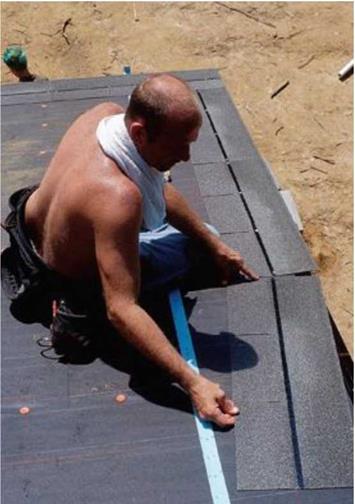
All shingles (including wood) are meant to overlap, providing a double layer of protection from the elements. That’s why the starter course must be two layers thick. For the first layer, lay the shingles the “wrong” way so that the three tabs face up. The stone surface should also face up (see the photo at left). Or you can buy starter shingles made just for this first course. Hold the long part of the shingle to the horizontal starter line and the right edge of the shingle to one of the vertical offset lines that you snapped near the center of the roof. With either a hammer or a pneumatic nailer, drive four Ts-in. large-head roofing nails into each shingle just above the tar strip (see the illustration on p. 137). The tar strip is near the center of each shingle and bonds one course to the next, keeping everything in place

Standard Stair (to be carpeted)

Adapt these guidelines for use when plans do not give details.

2 x 12 Stair tread:

1. Router nosing with V2" round router bit.

2. Glue and nail three 16d nails on each stringer for single residence use.

3. Glue and nail four 16d nails on each stringer for multi-residence use.

• Two stringers for single residence use, 36" or less width (depending on tread and riser material).

• Three stringers for multi-residence use, or treads larger than 36" (depending on tread and riser material).

Recap of Key Stair Guidelines

The following are important items to go over to make sure you end up with a good set of stairs:

• Check the code maximum and minimum widths, depths, and heights.

• Remember to review the floor finish on the top, the bottom, and any midway decks for different thickness in the finish floor material. For example, if there is going to be lightweight concrete on the floor sheathing, or if a carpet stair ends on a concrete slab, then the last tread height would have to be adjusted. It

is important to stay within the 3/8" height variance (specified in the codes) between all the risers.

• If you have a midway deck in the stairs, make sure you check the height. Figure the height and measure from the top or bottom of the stairs, and then check by figuring the height and measuring from the opposite of top or bottom. If you figured right, your marks should align.

Transport and Laydown of the SMA Mixture

Once the SMA has been produced at a hot mix plant, it must be transported to the job site where it will be placed and compacted. This chapter describes issues that need to be considered during this stage of the construction process.

10.1 TRANSPORT OF THE MIXTURE TO A LAYDOWN SITE

While it may seem that hauling SMA to the job site is straightforward, there are things that can go wrong that can affect the rest of the construction process and ultimately the performance of the pavement. This section will describe potential problems and how to prevent them.

10.1.1 Loading a Truck

The hot SMA mixture, at first stored in a silo, must be transported to the work site. The way the mixture is loaded into the bed of the truck affects its subsequent quality. The following rules should be observed to prevent segregation of the mix:

• The discharge into the bed of the truck should be performed in defined drops; generally the first drop should be placed in the front part of the load bed, the second one toward the rear, and the rest evenly distributed in the middle (Hensley, undated; Roberts et al., 1996).

• The addition of small amounts of mixture to reach the full weight limit of a loaded truck may bring about the separation of larger particles of the aggre­gate from the mixture (segregation) and should be avoided.

• When using trucks with large beds, the truck should be loaded in four or more separate drops, overlapping the individual dropped piles to help remix the material.

Detailed instructions for loading mixtures out of silos may be found in the USACE Handbook (2000).

The draindown effect (i. e., binder or mastic draindown followed by its collection on the bottom) may happen under the following circumstances (Ulmgren, 2000): [60]

Also, remember to suitably prepare the truck bed prior to loading the mixture. The bed should be clean and free from dirt (see requirements according to EN 13108-21). Sideboards and bottoms of the beds of the delivery trucks should be covered with a special release agent (antiadhesive fluid) to avoid adhesion; diesel oil and other fluxing agents that may degrade the bituminous binder are not permitted to be used in this capacity. The truck bed should be free of major dents in which substantial amounts of release agents could gather. The boards should be evenly coated, and any excess release agent that may collect in deformations of the bed should be removed prior to loading the truck.

Problems and Tips

Today almost all asphalt plants are computer controlled. It is worthwhile mentioning the necessity for caution during SMA production. This also applies to these modern asphalt plants. Usually such machines give personnel a feeling of confidence and a sense of complete control over the production process. However, many instances have proved that an excess of trust leads to problems (some of which are described in Chapter 11).

Particular attention should be paid to checking weight batchers, thermometers, and proportioning meters. All data produced by the computer system should be peri­odically checked. A good example of the type of problems that may occur is the clog­ging of batching devices for granulated stabilizers between the balance and the chute

image88

FIGURE 9.10 Performance inspection of the granulated stabilizer batching into a plant’s pugmill. (Photo courtesy of Krzysztof BlaZejowski.)

image89

Stabilizer

FIGURE 9.11 The SMA asphalt mixture with the stabilizer after extraction and before aggregate screening. (Photo courtesy of Krzysztof BlaZejowski.)

gate. The actual amount of stabilizer weighed out by the machine can be checked by disconnecting the chute pipe and measuring the amount of material batched during a production cycle (Figure 9.10). Another typical method is performing an extrac­tion and checking for the presence of the stabilizer in the mixture (Figure 9.11). Unfortunately this method does not allow for the determination of the exact amounts of fibers added to each batch.

Finally, a brief note about extraction. While performing an extraction of an SMA mixture, the rules for the correct preparation of the sample should be observed (hav­ing the stabilizer in mind as the mixture’s constituent—see Figure 9.11). The stabi­lizer fibers should be removed prior to starting the aggregate screening.

Factory Production Control after EN 13108-21

Issues concerning procedures for production of bituminous mixtures under EN 13108-21 and specified tolerances are discussed in Chapter 14.

9.5.2 Other Examples of Production Control

Some brief examples from around the world include

• In some countries, the accuracy of stabilizer dosage is ±10% of its mass as determined in a laboratory formula.

• If binder viscosity is the basis for establishing the mixing temperature of a binder and aggregate, some specifications may quote a permissible devia­tion from that temperature (e. g., ±10°C).

• In most countries, the permissible deviation of a mixture gradation and the content of binder depends on the number of tested samples.

• Some regulations provide clauses permitting a situation in which the grada­tion curve of a produced mix, considering given deviations, may deviate outside the area of the gradation envelope (between the so-called upper and lower limit curves).

Who burned the Library of Alexandria?

The legend that attributes the arson of the Library of Alexandria to Julius Caesar is ques­tioned today. We have seen clearly, to the contrary, that the intellectual movement of Alexandria knew a second fruitful period under the Roman Empire. In this period, it is a procurator supra museum et ad Alexandrina Biblioteca, named by the Roman prefect, who administers the Museum and the Library.[204] [205] It is generally accepted that the period of greatest creativity at the institution was in the 2nd century of our era.

However, we should remember that it is only a short time before the capture of the city by the Arabs, in 642, that one finds Jean Philopon’s most virulent critique of the Physics of Aristotle. Thus to the extent that periods of intellectual decadence are reflect­ed in the absence of a critical view of the treatises of the ”ancient greats”, Alexandria remained a great intellectual center to the very end.

But in a world that insists on rushing toward a precipice, important discoveries and ideas are destined for oblivion. The legendary burning of the Library is a symbol of this headlong rush: did the books merely burn, or was it the intellectual drought of troubled times that prevented the survival of the theories of Heron, Jean Philopon, and so many others?[206] There certainly were episodes of book destruction during the period of the last centuries of Roman domination, either as acts of war, or as the ravages of religious fanaticism. In 290 AD, during the re-taking of Alexandria after it had been conquered by Zenobia, queen of Palymyra, an entire section of the city is set aflame. In 391, the bishop Theophilos intentionally destroys the library of Serapeion. And in 640, after the taking of Alexandria by the Arabs, the remaining 54,000 books are burned as fuel for the public baths, on the order of the caliph Omar. According to the tradition reported by Arab historians, Jean Philopon tried in vain to persuade the conquerors to spare the

books.[207]

Environmental Factors

Important environmental factors that affect culvert durability include the acidity (pH) of the effluent and the soil, the electrical resistivity of the effluent and the soil, and the concentration of sulfates and chlorides. Data on these factors should be obtained at each pipe location, unless a random sampling plan is justified by establishing that the samples are uniform throughout a given length of the project. Water samples should be taken only during times of typical flows. If corrosive conditions are found to be present in the soil but not in the water samples, consideration should be given to using a better backfill material.

Concrete Pipe. Environmental factors that can affect the deterioration of concrete culverts include freeze-thaw, acids, sulfates, and chlorides. Freeze-thaw damage can occur if water penetrates the concrete interstices and then freezes and expands, causing cracking. Such damage would occur only at exposed ends of culverts, and low water – cement ratios or air entrainment can increase resistance. Continuous exposure to severe acidity is detrimental to concrete pipe; a pH below 5.0 is considered aggressive and below 4.0 highly aggressive. Improved resistance to acid attack can be attained by selecting aggregate that increases the total alkalinity of the concrete, increasing concrete cover over reinforcement, or adding barrier linings (e. g., epoxy coatings). Sulfates in the soil, groundwater, or effluent can be aggressive to concrete. Such problems, which are generally limited to arid regions with alkali soils, may be addressed with special cements and mix design. Chloride attack can potentially result from use of deicing salts and subsequent runoff.

Metal Pipe. Environmental factors that affect the corrosion of metal culverts include the acidity (pH) and the resistivity of the soil and water, and the moisture content, sol­uble salt content, oxygen content, and bacterial activity of the soil. These corrosion processes all involve the flow of current from one location to another. The current flows from an anodic area to a cathodic area through moist soil acting as an elec­trolyte, and this system is known as a corrosion cell. Thus, durability increases with increasing resistivity. Acid soils, those with low pH, tend to be more corrosive. Also, soils with high moisture content, such as loams and clays, tend to be more corrosive. High levels of chlorides and sulfates increase corrosion, as do increasing levels of dis­solved oxygen and carbon dioxide. Numerous field studies have shown that the culvert invert is the portion most susceptible to corrosion, because it is generally exposed to water for a greater length of time. Thus, design charts are usually based on service life observed in the invert.

Plastic Pipe. PE and PVC pipe are not affected by acid conditions, or by sulfates or other alkalis. These materials can become embrittled from ultraviolet radiation as a result of prolonged exposure to direct sunlight, such as at culvert ends, but inhibitors are added to the composition of the material to substantially reduce this effect. If problems are encountered, ends can be shaded, covered with a coupling, or painted.

ESTIMATES FOR A ROOF

Determining the quantity of materials needed to cover and shingle a roof is rather easy. First, measure the roof to deter­mine its square footage. Add the width of both sides of the roof and multiply that number by the length of the roof. Let’s look at an example: A roof with an overall width of 28 ft. and a length of 46 ft. has a total area of 1,288 sq. ft., which I’d round up to 1,300 sq. ft.

FIGURE FELT PAPER FIRST. The first material you will need is felt paper. The coverage you can obtain from a roll of felt paper varies, but it’s often 300 sq. ft. (to make sure, ask your building-materials supplier). Divide 1,300 sq. ft. by 300 sq. ft. for a total of 4.33 or 41/3 rolls. Buy five rolls of felt paper, because you’ll need the extra to compensate for overlap and to seal around the plumbing vents.

SHINGLES COME IN BUNDLES AND ARE ORDERED BY THE SQUARE. One bundle of standard-size shingles covers 33.3 sq. ft. Three bundles cover 100 sq. ft. (10 ft. by 10 ft.), which is called a square. It takes 13 squares (39 bundles) to cover a 1,300-sq.-ft. roof. Order at least two extra bundles to make up for the ridge cap, the valley lap, and waste.

In addition to the shingles, you’ll need a ridge vent. Measure the length of the ridge to determine the size you’ll need. Depending on the manufacturer’s recommendations, vents can extend all the way across the ridge or to within 2 ft. of the roof’s edge at each end.

DON’T FORGET THE NAILS. Buy 7/s-in. roofing nails for the shingles (about 1 lb. per square) and 11/2-in. nails for the ridge vent (about У2 lb.). Buy coil nails if you are using a pneumatic nailer. If the eave overhangs will be exposed, buy 2 lb. of 5/s-in. roofing nails; longer nails that penetrate the roof sheathing are unsightly. You’ll also need about 5 lb. of plastic-head roofing nails to hold the felt paper in place on a roof this size. Add a tube or two of asphalt caulk to cover any exposed nails and to seal around the plumbing vents.

Подпись: Back in the days when I was a roof shingler, I hardly ever saw asphalt or fiberglass (composition) shingles. Being a shingler meant working with wood shingles. Now in most parts of the country I see wood shingles used more often on the sides of buildings than on roofs. Composition shingles are more popular because they are faster to install and more resistant to fire. Give some thought as to the color and style of the shingles that you want on your house. A new style of architectural shingle that casts a shadow has become popular. Light-colored shingles reflect more heat than dark ones do. For this reason, people living in the southern part of the United States tend to prefer light- colored shingles. People living further north often select darker shingles. Lay out the shingles With some simple layout, your shingles can look like a professional installed them. Poorly laid shingles may keep out water, but they just don’t look appealing. Admittedly, not many people visit your home just to see whether your shingle pattern is pleasing to the eye, but good workers take pride in doing things right. When I was framing tract houses (500 at a time), I knew roofers who could start in one corner and shingle an entire roof without snapping a chalkline and do a neat, proper job. That’s skill. The rest of us need to snap a few lines to keep the materials oriented correctly. BASIC MEASUREMENTS. Before snapping a chalkline for the first shingle course (the starter course), determine the distance the shingles will extend beyond the drip edge. Here in Oregon, shingles typically lap over the edge by about Vi in. I worked on houses in Georgia where the shingle overhang was about 2 in. They drooped in the hot sun and provided the roof with a nice-looking detail. Just be aware that a large shingle overhang presents a greater surface area to heavy winds, making them more vulnerable and likely to tear or rip off. Check Don’t let shingles get sunburned. Don’t store asphalt shingles in the sun, unless you’re going to use them right away. The tar strips can melt and seal the shingles together into a big, useless mess. If you must store shingles, put them in the shade or cover them with a light-colored tarp to reflect the heat.
the shingle manufacturer’s recommendations for overhang.

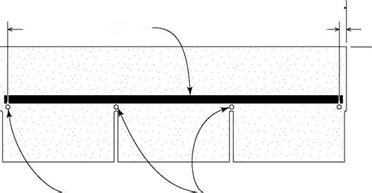
As shown in the illustration at right, a stan­dard three-tab shingle measures 12 in. wide by 36 in. long. Each of the three tabs measures 12 in. across. (Dimensional or metric shingles are a bit larger. To install them, read the instructions printed on the package.) If you want 12-in. shin­gles to hang over the edges by ‘/2 in., for example, measure ПУ2 in. from the outside edge and snap chalklines around the roof’s perimeter. VERTICAL LAYOUT LINES. Sometimes referred to as bond or offset lines, vertical layout lines keep shingles aligned and ensure that you don’t end up with a narrow section of shingle when you get to the edge of the roof. There are different ways to establish vertical layout lines. The best method I’ve seen is explained in the sidebar on p. 138. My thanks to Habitat veteran Anna Carter and other volunteers, who figured out this vertical layout technique. HORIZONTAL LAYOUT LINES. Once the vertical layout lines are in place, you can lay


111111111111111111111111111111111111111111111111111111111111111111111111111111111111111111111111111111111111111111111111111111111111111111111111111111111111111111111

SHINGLE ANATOMY AND NAILING DETAILS


36 in.


Tar strip


3/4 in.


3/4 in.-


in.


Nails between slots and tar strips


7/8-in.

roofing nails


out the horizontal lines. To do this, you must know the reveal—the part of each shingle that remains exposed (“to the weather”) after the next course is installed. On standard shingles, this distance is usually 5 in. Therefore, on a 12-in.-wide shingle, 7 in. will be covered by the next course. Some manufacturers recommend


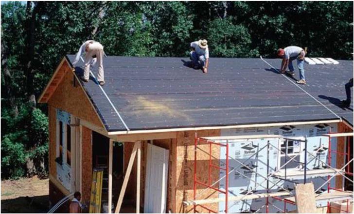
Snapped with red chalk, vertical and horizontal layout lines ensure proper shingle alignment and al­low shingling work to go quickly.


ESTIMATES FOR A ROOFESTIMATES FOR A ROOF