Simplicity

It is ironic that simplicity is by far the most difficult of the seven principles to achieve. Simplification is a complicated process. It demands that every pro­portion and axis be painstakingly honed and that every remaining detail be absolutely essential. The more simplified a design becomes; the more any imperfection is going to stand out. Everything in a plain design must make sense, because every little thing means so much. The result of this arduous effort will look like something a child could come up with. The most refined art always looks as if it had been easy to achieve.

This sort of streamlining demands a firm understanding of what is neces­sary to a home. As stated before, there is no room in an honest dwelling for anything apart from what truly makes its occupant(s) happy. Each one of us must ultimately decide what this is and is not for ourselves. But, as with all good vernacular processes, we should first consider the findings of those

who have gone before us. While our domestic needs will differ as much as our location and circumstances, a look at what others consider to be impor­tant can get us going in the right direction.

Ideas about what is indispensable to a home can be concise so long as they are kept abstract. Consider Cicero’s claim: "If you have a garden and a library, you have everything you need.” And William Morris’ sage advice: "Have nothing in your houses that you do not know to be useful, or believe to be beautiful.” More pragmatic lists tend to be a bit longer. Small house ad­vocate, Ron Konzak, is helpful. In his essay, entitled: “Prohousing,” Konzak explains that most every domicile should provide…

1. Shelter from the elements.

2. Personal security.

3. Space for the preparation and consumption of food.

4. Provision for personal hygiene.

5. Sanitary facilities for relieving oneself.

6. Secure storage for one’s possessions.

In their now-famous book, A Pattern Language, Christopher Alexander and his colleagues provide a detailed list of no fewer than 150 items for possible inclusion in a home. I have made a similar, albeit far less detailed, list here. More asterisks indicate a more universal need for the item they accompany.

EXTERIOR:

1. A small parking area out back.

2. A front door that is easily identified from the street.****

3. A small awning over the door to keep occupants dry as they dig for keys and guests dry as they wait for occupants.**

4. A bench next to the front door on which occupants can set things while fumbling for keys or sit while putting on/off shoes.

5. A window in the front door.

6. A steeply-pitched roof to better deflect the elements.*

7. Adequate insulation in all doors, windows, walls, the floor and the roof.****

8. Windows on at least two sides of every room for cross ventilation and dif­fuse, natural light.

9. Windows on the front of the house.**

10. A structure for bulk storage out back.

11. A light over the front door.

12. No less than 10 square feet of window glass for every 300 cubic feet of interior space.**

13. Eaves

ENTRY:

14. A light switch right inside the front door.*

15. A bench just inside the front door on which occupants can set things while fumbling for keys or sit while putting on/off shoes.

16. A closet or hooks near the door for coats, hats and gloves.*

A PLACE TO SIT:

17. A chair or floor pillow for each member of the household.****

18. Some extra chairs or pillows for guests. (In bulk storage?)*

19. A table for eating, with a light overhead.**

20. A table for working, with a light overhead.**

21. Nearby shelves or cabinets for books, eating utensils or anything else pertinent to the activity area.

22. A private place for each member of the household.***

23. A phone.

A PLACE TO LIE DOWN:

24. A bed.***

25. A light at or above the head of the bed.

26. A surface near the head of the bed on which to set a clock, tissue, books, etc.

APPLIANCES AND UTILITIES:

27. Electricity and a place for the accompanying fuse box.**

28. A source of water and sufficient room for water pipes.***

29. A water heater.**

30. A source of heat.**

31. A place for an air conditioner.

32. Ventilation and room for any accompanying ductwork (windows can sometimes work to this end).****

33. An indoor toilet.*

34. A tub or shower.***

35. A towel rack near the tub or shower.**

36. A mirror.**

37. A home entertainment center.

38. A washer/dryer.

A PLACE TO COOK:

39. An appropriately-sized refrigerator.

40. A stove top.*

41. An oven.

42. A sink.***

43. A work surface for food preparation with a light over it.**

44. Shelves or cabinets near the work surface for food and cooking sup­plies.**

ADDITIONAL BULK STORAGE:

45. A laundry bin.

46. No less than 100 cubic feet of storage per occupant for clothes, books and personal items.****

These items are not mutually exclusive. Where one can serve two or more purposes, so much the better. The dining table, for example, may double as a desk. This is especially true in a one-person household, where a single piece of furniture will rarely be used for more than one purpose at a time. Also, keep in mind that many of these things can be tucked away while not in use.

This list is meant to be a starting place from which anyone can begin to de­cide what is necessary to their own home. Certainly, what I propose to be universal requirements will not be universally agreed upon. The only needs that really matter in the design of a home are those of its occupant(s). The important thing to keep in mind when creating one’s own list is that the less significant a part is to the whole and its function, the more it will diminish the quality of the overall design. Just remember when to say "when.”

Water and Soil Sampling Procedures

7.4.1 Introduction

The procedure for sampling is primarily influenced by the source of the water (e. g. in a borehole, in a pipe) and by the equipment available with which to sample it. The equipment, itself, is largely controlled by the sampling location. Once collected by the sampling device, water samples must be quickly processed before changes in make-up occur due to various physical and biological processes. The following sections discuss the collection and immediate treatment of surface and sub-surface waters and of soil. They provide a general overview of the techniques and pro­cedures for application in pavements and the ground around highways. There is insufficient space to cover all aspects of sampling techniques and practice, so inter­ested readers are directed to other texts where these aspects are fully described. In particular, reference may be made to the following sources : [18]

Insulated Glass Reduces Heat Loss

Manufacturers typically refer to glass as glazing. Using glazing as a noun is a bit pretentious, like referring to a window as a fenestration, but it does give the sense that glass assemblies in today’s windows are a far cry from the single-pane windows installed in the 1970s.

Those single-pane windows have been abandoned in most heating climates be­cause glass is a horrible insulator. A standard window today relies on an insulated glass unit (sometimes called an IG). This unit is a sealed sandwich of two or three pieces of glass with an airspace between the panes. IG units are manufactured by a few glass com­panies that supply the hundreds of window manufacturers in North America.

Подпись: What's a U-Factor?Подпись: U-factor rates a window's insulating properties by measuring the flow of nonsolar heat through the window. You can think of it as the rate of conduction; the lower the U-factor, the less heat will flow through the window. (U-factor is the reciprocal of the more familiar R-value used to rate insulation. R-value measures resistance, so higher numbers are desirable.) Although we tend to think of a window as primarily glass, the frame makes up 20% to 30% of the unit. U-factors are measured for the edge of the glass area, the center of the glass area, and the frame; but the important U-factor is for the entire window unit. Buy Insulated Glass Reduces Heat Lossing decisions should be based on this number, which appears on the NFRC label (above).

U-factors for operable windows range from 0.14 for a super­insulating suspended-film unit to 0.5 or so for a basic double-pane window from a big-box store. Lower U-factors correlate with higher prices.

The airspace between glass panes, usually V2 in. to 2/з in. thick, serves as insulation by reducing the transfer of heat through con­duction. A single clear pane has a U-factor of 1.04, but a sealed double-pane unit has a U-factor of 0.5 (see "What’s a U-Factor?" above). Adding a third pane improves the U-factor to 0.3.

Replacing the air with gas improves the insulating value of the window. Manufactur­ers use argon or krypton gases because they’re inert—chemically stable and nonreactive— and because they reduce heat loss, as they are less conductive than air. Argon and krypton also reduce convective losses because the gases are heavier than air, reducing gas movement within the insulating space.

Krypton performs slightly better than ar­gon, but its bigger advantage is that the op­timal spacing between krypton-filled panes is narrower than what’s required for argon. That means less stress on the sashes, particu­larly in triple-pane windows.

Spacers Are Potential Weak Points

Spacers between glass panes perform three functions: They maintain a uniform separa­tion between pieces of glass, they provide a good adhesive surface for the glass, and they create an airtight seal for the insulating cavity.

Although you should choose windows based on their overall performance ratings, the spacer, while small, substantially impacts a window’s U-factor and condensation resistance.

The spacer’s job is complicated by the fact that it’s in contact with both the inside and outside surfaces of the window, forming a bridge between indoor and outdoor environ­ments. Because the spacer is more conduc­tive than the air or gas fill, it changes the temperature of a 21/2-in.-wide band around the edge of the glass. As a consequence, the window’s overall U-factor is affected. In smaller windows, the 21/2-in. temperature band is a larger percentage of the window and has a greater effect on the window’s U-factor. While spacers can be considered the Achilles’ heel of all windows, a casement window performs slightly better than a double-hung of the same size because the former has less spacer area. Likewise, the thermal performance of true divided-lite windows made up of multiple IG units suf­fers because of all the spacer area in the win­dow. (Simulated divided lites can also affect U-factor if the grille creates a thermal bridge between the panes.)

Spacers are made of aluminum, steel, fiberglass, foam, and thermoplastics, often in some combination. Foam spacers have the lowest U-factor, while aluminum has the highest. Today, quality windows use "warm – edge" spacers. (It’s worth noting that warm – edge means only that it’s less conductive than aluminum.) A good warm-edge spacer raises the interior surface temperature of the glass along the perimeter of the window.

This is especially important at the window’s

Подпись:bottom edge, which is most subject to con­densation. At 0°F outside, a good spacer in­creases the temperature at the bottom of the inside glass pane by 6°F to 8°F. As a result, a more comfortable relative-humidity level indoors is possible during the winter with­out window condensation.

Size Determination for Long-Span Structures

Because culvert shapes are so numerous and new shapes are often developed, design charts showing performance curves are not available for all culvert sizes and shapes. One example is long-span corrugated-metal sectional plate structures. Although the product is available in several cross-sectional shapes, performance curves are avail­able only for circular or elliptical cross-sections (Fig. 5.17) and high – and low-profile arches (Fig. 5.18). These charts, which are for inlet control only, address four different inlet configurations ranging from mitered to beveled-edge ends. Because long-span structures are commonly used when headroom is low, they generally do not flow under head at design discharge but flow partly full.

The first step in using these charts is to obtain information on available sizes, including cross-sectional area A (ft2) and vertical height D (ft). For the design dis­charge Q (ft3/s), calculate Q/AD05 and read the value of HW/D at the intersection of the appropriate edge condition curve. Multiply by the depth (height) of the structure (D) to obtain the headwater depth HW and compare with the allowable design value. To consider a long-span structure under outlet control, an analysis including pressure flow and backwater calculation can be made. (See “Hydraulic Design of Highway Culverts,” HDS 5, FHWA.) The inlet and outlet control headwater elevations are then compared. The higher value is compared against the allowable elevation to determine if the size is satisfactory or if the process should be repeated.

Size Determination for Long-Span Structures

Size Determination for Long-Span Structures

FIGURE 5.18 Performance charts for high – and low-profile structural-plate arches under inlet flow control. (From “Hydraulic Design of Highway Culverts," Hydraulic Design Series No. 5, FHWA with permission)

Time-dependent resistance

For a hydraulic structure placed in a natural environment over a period of time, its operational characteristics could change over time owing to deterioration, aging, fatigue, and lack of maintenance. Consequently, the structural capacity (or resistance) would vary with respect to time. Examples of time-dependent characteristics of resistance in hydrosystems are change in flow-carrying capacity of storm sewers owing to sediment deposition and settlement, decrease in flow-carrying capacity in water distribution pipe networks owing to aging, seasonal variation in waste assimilative capacity of natural streams, etc.

Modeling time-dependent features of the resistance of a hydrosystem re­quires descriptions of the time-varying nature of statistical properties of the resistance. This would require monitoring resistance of the system over time, which, in general, is not practical. Alternatively, since the resistance of a hydrosystem may depend on several stochastic basic parameters, the time – dependent features of resistance of hydraulic structures or hydrosystems can be deduced, through appropriate engineering analysis, from the time-varying behavior of the stochastic parameters affecting the resistance of the systems. For example, the flow-carrying capacity of a storm sewer depends on pipe slope, roughness coefficient, and pipe size. Therefore, the time-dependent behavior of storm sewer capacity may be derived from the time-varying features of pipe slope, roughness coefficient, and pipe size by using appropriate hydraulic models.

Although simplistic in idea, information about the time-dependent nature of stochastic basic parameters in the resistance function of a hydrosystem is gen­erally lacking. Only in a few cases and systems is partial information available. Table 4.6 shows the value of Hazen-Williams coefficient of cast iron pipe types

TABLE 4.6 Typical Hazen-Williams Pipe Roughness Coefficients for Cast Iron Pipes

Age (years) new

Pipe diameter all sizes

Roughness coefficient Chw 130

5

>380 mm (15 in)

120

>100 mm ( 4 in)

118

10

>600 mm (24 in)

113

>300 mm (12 in)

111

> 100 mm (4 in)

107

20

>600 mm (24 in)

100

>300 mm (12 in)

96

> 100 mm (4 in)

89

30

>760 mm (30 in)

90

>400 mm (16 in)

87

> 100 mm (4 in)

75

40

>760 mm (30 in)

83

>400 mm (16 in)

80

> 100 mm (4 in)

64

SOURCE: After Wood (1991).

as affected by pipe age. Owing to a lack of sufficient information to accurately define the time-dependent features of resistance or its stochastic basic parame­ters, it has been the general practice to treat them as time-invariant quantities by which statistical properties of resistance and its stochastic parameters do not change with time.

The preceding discussions consider the relationship between resistance and time only, namely, the aging effect. In some situations, resistance also could be affected by the number of occurrences of loadings and/or the associated intensity. If the resistance is affected only by the load occurrences, the effect is called cyclic damage, whereas if both load occurrence and its intensity affect the resistance, it is called cumulative damage (Kapur and Lamberson, 1977).

Galien of Pergamon and the beginnings of biomechanics

There is another branch of fluid mechanics that sees some early development in this peri­od: this is the knowledge of blood circulation. Whereas it was believed that the arteries contained only air prior to this period, Galien of Pergamon (129 – 200? AD)[202] is the first to describe arterial circulation and to study seriously the circulation of blood in the heart. For this he relies on an intense practice of dissection.[203] His only error is in believing that the blood passes directly from the right ventricle to the left ventricle.

The first discovery of the resistance to motion through the air

We mentioned in Chapter 4 the dominant theory of Aristotelian Greek science on the movement of objects in air. This theory held that air actually entrains the movement of a body (a thrown spear or an arrow) rather than slowing down this movement. In this theory, the air displaced by the front of the projectile comes back to the rear and pushes the object in its flight. Jean Philopon of Alexandria (in the 6th or beginning of the 7th century BC), in his Critique of the Physics of Aristotle, strongly rejects this theory:

”How could it be that the air, pushed by the arrow, does not move in the direction of the impulse that has been given to it, but instead does an about-face, as if ordered to do so, and backtracks? Moreover, how could it be that this air, in this about-face, does not disperse into space, but instead returns to strike precisely the notched end of the arrow, continuing to push it and stick to it? Such a conception totally lacks plausibility, and smacks of fiction. z

Later in the same work, Jean Philopon suggests that it is indeed the thrower who “provides the motive force for the rock” (which is what will later be called the kinetic energy or momentum). He also says that “if one imparts an unnatural movement, or a forced motion, upon an arrow or a stone, the same degree of motion will be attained more easily in a vacuum.” Continuing his discourse through the description of experi­ments with falling bodies, Jean Philopon observes that the time of fall depends very lit­tle on the weight. He shows finally that the air does indeed exert a resistance to the advancement of the body in motion.

Critical Depth Determination

Подпись: IOO Подпись: 150 Critical Depth Determination Подпись: 350

The critical depth for various culvert cross-sections may be found from charts in HEC 5. An example is given in Fig. 5.16 for a rectangular section. In this case, the ratio of the flow Q (ft3/s) to the width B (ft) is used to find the critical depth dc (ft). Of course, dc cannot exceed the depth of the box section.

Подпись: MOTEac CANNOT EXCEED D

Heron of Alexandria and the first expression of the volumetric discharge of a canal

Before Heron, no correct notion of the discharge of a canal, pipe, or river had been cor­rectly formulated. Indeed, the notion of velocity was essentially unknown in Greek mechanics. The quantity of water delivered by an aqueduct or canal was quantified uniquely by a measure of the flow area. It was Heron who formulated for the first time the notion that the volumetric discharge, i. e. the volume of water delivered in a unit of time, is the product of the flow area and the velocity. One finds the following in his work Dioptra:

“It is to be noted that in order to know how much water the spring supplies it does not suffice to find the area of the cross section of the flow… It is necessary also to find the speed of the flow, as the swifter the flow is, the more water the spring supplies.”[201]

The importance of the current velocity in calculating the discharge is thus estab­lished, but Heron did not have any means of measuring this velocity. So he also pro­posed another means of calculating the quantity of water delivered in a day:

“One should therefore dig a reservoir below the stream and note with the help of a sundial how much water flows into the reservoir in a given time, and thus calculate how much will flow in a day. The amount of water will be clear from the measure of the time.”

Coming too late to be useful to the Romans, who were the great constructors of this period, the concept is destined to be gradually forgotten over time. It is only in the West during the Renaissance that it will once again be formulated.

Production of SMA in a Drum-Mix Plant

There are two types of drum-mix plants: parallel-flow drum-mix plants and counter-flow drum-mix plants (conventional and double barrel). In drum-mix plants, cool aggregate is delivered from cold-feed bins to a dryer-mixer and then into a silo through a slat conveyor. The mixture gradation control is exercised
through establishing suitable proportions of individual aggregate fractions in cold-feed bins and the rate of aggregate supplied by the feeder belt. The conveyor is equipped with a weight and speed-control system that enables control over the coating plant’s throughput in tons per hour. The general categories of drum-mix plants depend on the flow direction of the aggregate relative to the hot air move­ment from the burner. In parallel-flow drum-mix plants, the aggregate and hot air move in the same direction, while in counter-flow drum-mix plants, they move in opposite directions.

In classic parallel-flow drum-mix plants, the asphalt binder is delivered to a dryer- mixer and injected on the aggregate tumbling inside, which poses a risk of direct contact between the binder and exhaust gases from the dryer’s burner. That is why various solutions have been adopted that place the binder batching point away from the burner and the aggregate drying zone.

In counter-flow drum-mix plants, the aggregate moves in the direction opposite to the movement of exhaust gases. Many precautionary design measures have been built in and are supposed to provide a significant reduction in emissions, a reduction in the exhaust gas temperature, and protection of the binder against overheating. A lengthened part of the drum where mixing takes place, an extra coater, and an embedded burner are a few examples of these solutions. In counter-flow drum-mix plants of the double-barrel type, the aggregate is dried in an inner drum, then dis­charged into the surrounding outer drum, where it is mixed with binder while being protected from the burner’s high temperature. The final asphalt mix is transported to a storage silo with a conveying device.

The SMA aggregate mix contains more than 70% m/m coarse particles, which means that a substantially higher amount of energy is needed to dry and heat them than when manufacturing asphaltic concrete. Furthermore, it may be neces­sary to reduce the output of the coating plant and to extend the veil of aggregate flowing through the dryer-mixer per time unit to obtain the proper aggregate temperature.

Adding a loose fiber stabilizer represents a severe handicap from a produc­tion control standpoint; the location of batching should be chosen carefully so that the loose stabilizer cannot be captured by hot exhaust gases. However, the application of granulated fibers does not present major problems, provided that the point of their addition into the mix is properly determined. Adding granulate to the drum behind the burner (parallel-flow or conventional counter-flow) or to the outer drum before adding binder (counter-flow double-barrel system) is the rule.

Hurricane clips and frieze blocks

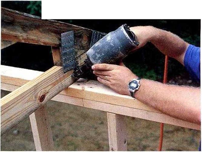
A hurricane can tear a roof completely off a house. Hurricane clips, which are designed to prevent this, are required by code in some parts of the country. After the trusses are nailed in position, hurricane clips are easy to install from inside or outside the house. Drive nails into the trusses and the top p. atesofthe wall (see the photo at left). Be sure to use the special short, strong “hanger” nails that arc sold with the clips.

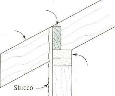
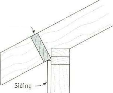
In many parts of the country, frieze blocks are required between trusses. I’m in favor of these blocks, which you can cut from the plentiful supply of 2x scrap that your crew has been collecting. Installed at the top of the wall, these 2x blocks connect the bottom chords or, depending on the truss design, the rafters of adjacent trusses. They provide extra rigidity near the truss ends (see the illustration at left).

1 have seen firsthand how frieze blocks help hold truss systems together in high winds and earthquakes. They offer other benefits as well. The blocks can serve as exterior trim (with or without ventilation holes) if you plan to have an open soffit. If you are installing raised-heel trusses, as we did on this house, you’ll also need to install plywood or OSB baffles between the trusses to prevent attic insulation from spilling into the soffit area (see p. 51).

Install a pair of frieze blocks after each truss is installed. Drive a pair of 16d nails through the truss and into the end of the frieze block, then nail the frieze block to the top plate. You can cut a supply of blocks quickly on a chopsaw. Make sure you cut them to the correct length. If they’re toe long or too short, vou mav force the trusses off of their layout. The normal block length for trusses spaced 2 ft. o. c. is 22; in. However, if the


INSTALLING FRIEZE BLOCKS BETWEEN
RAFTERS AND TRUSSES


2x frieze block


Rafter


Nailing details:

1. Drive two 16d nails through the opposite side of the rafter or truss chord into the end of the block.

2. Nail the bottom of the block to the wall.


Double top plate


Venting option:

З-in. dia. holes can be drilled in frieze blocks and covered (from inside) with screen to provide ventilation along the eaves.


When installed plumb, a frieze block provides backing for stucco.


Rafter

2x frieze

block


When installed perpendicular to the rafters, blocking provides a stop for other types of siding.


Hurricane clips and frieze blocksHurricane clips and frieze blocks

Подпись:  •Hurricane clips and frieze blocksПодпись:

blocks will butt against gusset plates, you’ll need to take the gusset thickness into account. After vou’ve nailed the first frieze blocks

4

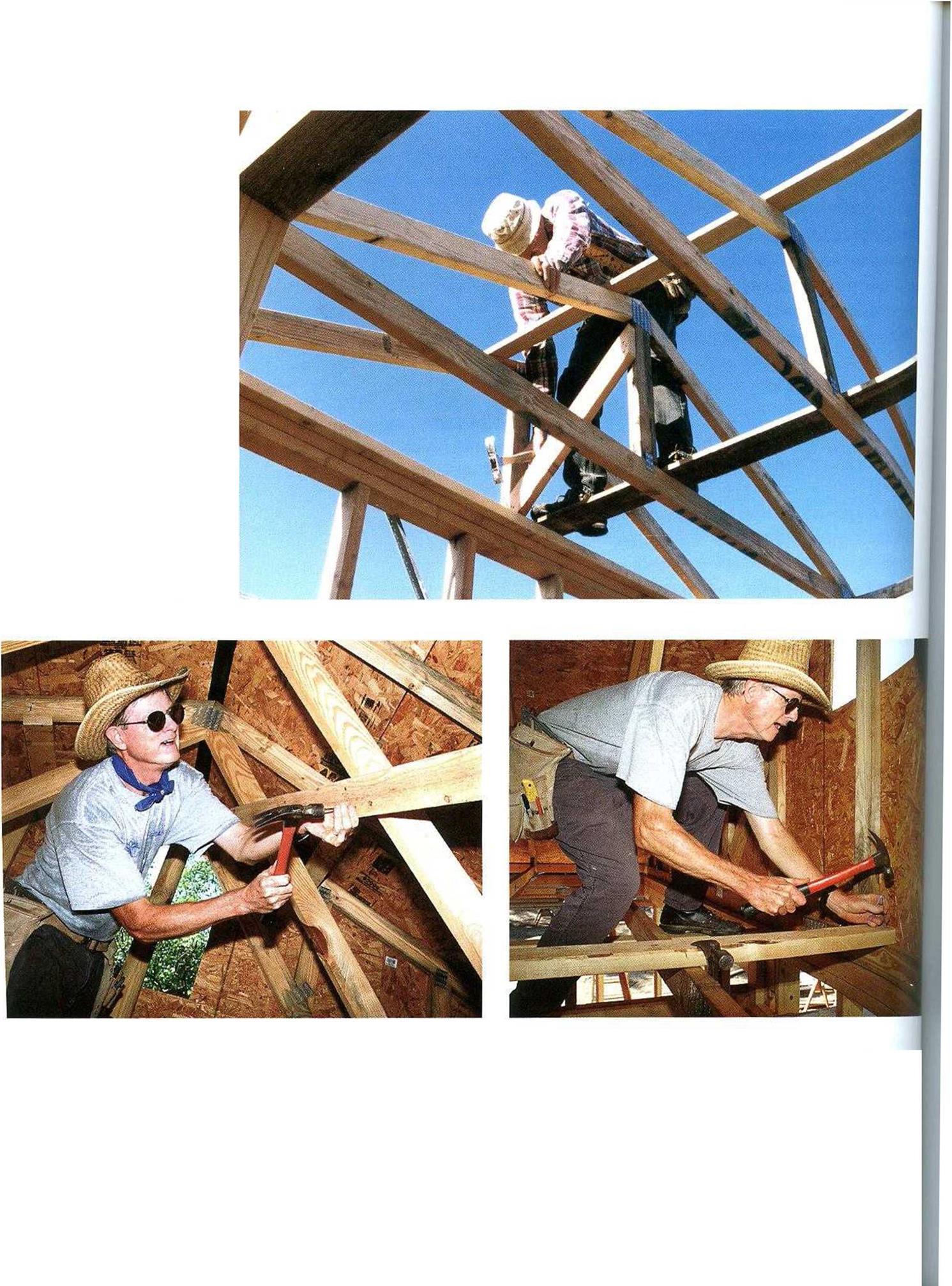
to the gable-end truss, swing the next truss upright. Shift it right or left, as necessary, to obtain the correct cave overhang, then toenail it to the top plate with two 16d nails through the joist chord on one side and one 16d nail on the other side (see the top photo at right). Install the next several trusses in this fashion. As you raise each truss, tack a series of 16-ft. Ix4s (laid out 24 in. o. c.) near the ridge of the rafter chord to keep the truss stable and properly spaced (see the bottom photo at right).

An efficient way to work when installing roof trusses is to have a worker at each cave toenailing the truss to the wall and installing frieze blocks while one or two crew members work on the ridge, moving trusses into posi­tion and nailing 1×4 braces to maintain proper spacing.

Plumb and brace the trusses

When bracing trusses, take time to read and follow the directions from the engineering company. These, along with local building codes, must be followed to guarantee that the house will have a strong and stable roof. Most simple gable truss roofs are easy to brace.

After four to six trusses have been installed, plumb the gable-end truss and begin bracing the roof. Use a level to plumb the end truss, then install a diagonal 2×4 swav brace from the double top (cap) plate of the exterior wall (where the gable-end truss is installed) to an inboard truss (see the top photo on p. 126). The brace should extend at a 45-degree angle from the top plate and be nailed to the top chord (or At) or the webbing of an inboard truss.

INSTALLING PERMANENT BRACING INSIDE. Shown in the top photo, a diagonal brace from the top of a truss down to a wall plate helps hold the trusses plumb. Install a 1×6 or 2×4 catwalk on top of the trusses’ bottom, or joist, chord. The brace should be nailed into every joist chord and into the end-wall top plates (photo at right, above). Nailing 2x bracing across the webbing provides the roof structure with additional rigidity (photo at left, above). [Top photo by Roe a. Osborn

Hurricane clips and frieze blockscourtesy Fine Homebuihiinq magazine, The Taunton Press, Inc.]
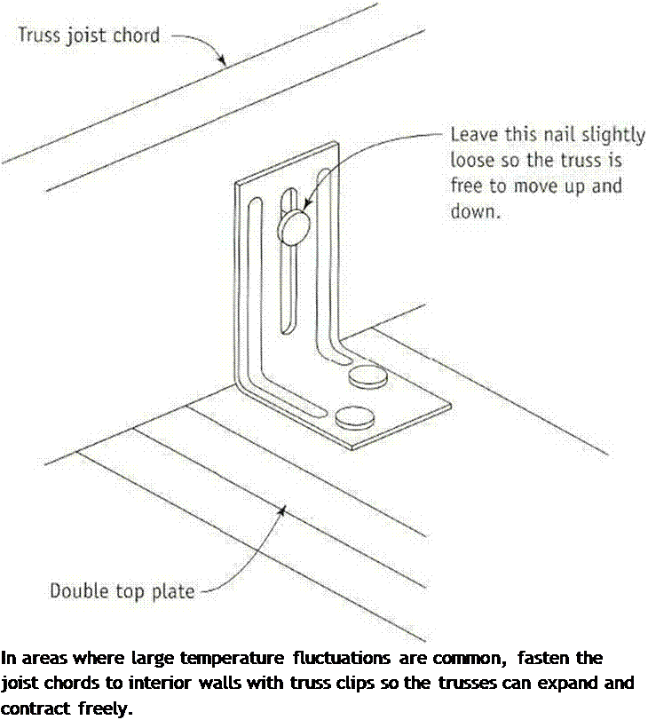
Подпись: ATTACHING TRUSS CLIPS Подпись: In areas where large temperature fluctuations are common, fasten the joist chords to interior walls with truss clips so the trusses can expand and contract freely. Подпись:Подпись: Helping HandПодпись: Be aware of overhead issues. If you're working on the ground while people are working overhead, stay alert while you are in the "drop" zone. Even though workers know not to drop things from above, it's easy to drop tools and materials accidentally.

If the gable-end rafter is plumb, the rafters tied to it at 24 in. o. c. should also be plumb. When all of the trusses have been installed, nail in a svvav brace at the other end of the roof. On longer roofs, use additional diagonal

swav braces near the center of the house to

і

further strengthen the roof.

The next step is to stabilize the joist chords by nailing a long board (a lx or 2x will do) on top of each joist chord near the center of the span. You can move this bracing to one side or the other if voи need to accommodate an opening for attic access (see p. 130). Nail this long brace to each chord with two 8d (for lx stock) or 16d (for 2x stock) nails (see the bot­tom right photo on the facing page). Addi tional 2×4 braces are often nailed at 45-degree angles across the underside of t ie rafter chords or webbing from the plate line to the ridge (seethe bottom left photo on the facing page). Nail these braces into each chord with two 16d nails. This provides lateral stability to the entire roof.