Honesty

In the most beautiful houses, no attempt is made to conceal structural ele­ments or disguise materials. Because wooden collar beams are understood as necessary, they are also seen as beautiful. Whenever possible, features like these are left unpainted and exposed to view. Then there are those hous­es for which attempts are made to mimic the solid structure and materials of more substantial homes. These are easily recognized by their wood-grain textured, aluminum siding, hollow vinyl columns and false gables.

Aluminum is a fine material so long as it is used as needed and allowed to look like aluminum. Artifice is artless. It does not merely violate nature’s law of necessity, but openly mocks it. If wood is required for a job, wood should be used and allowed to speak for itself. If aluminum is required, aluminum should be used and its beauty left ungilded whenever possible.

Ornamental gables are to a house what the comb-over is to a head of hair. The vast disparity between the intention and result of these two contrivances is more than a little ironic. Both are intended to convince us that the home­owner (or hair owner, as the case may be) feels secure in his position, but as artifice, each only serves to reveal insecurity and dishonesty.

False gables are tacked onto the front side of a property in a vain attempt to prove to us that the house is spectacular. While this effort is not fooling anybody, it is effectively serving to weaken the structural integrity of the roof. The more parts there are in a design, the more things can go wrong. Leaks almost never spring on a straight-gabled roof, but in the valleys between gables, they are relatively common. Unnecessary gables compromise sim­plicity for what is bound to be a very expensive spectacle.

STORING THE READY-MADE SMA MIXTURE IN A SILO

Most guidelines for SMA do not recommend producing large quantities of a mix­ture and holding it in reserve for too long for future use. SMA stockpiling is an uncertain business due to the risk of binder draindown when storing hot mixture. Such limitations cause problems when the asphalt plant has a low output and large amounts of mixture are needed to be supplied to a laydown site. It can be assumed that, depending on the temperature, mineral composition, and binder content, the mixture may be stored for up to 2 or 3 hours at a high temperature. The risk of draindown is magnified by the SMA’s extended storage time in a silo, which is why it should be sent to the work site within a reasonable amount of time after production.

It is important to monitor the decreasing temperature of a mixture in a silo. Not every silo is equipped with heated walls or even a heated chute. Allowing the mix to cool substantially in the silo may cause many problems, especially with a polymer – modified binder. It has been stated in the U. S. Department of Air Force guidelines (ETL 04-8) that a ready-made SMA mixture can be stored for no longer than 1 hour in uninsulated silos or 4 hours in thermally insulated silos. If, for any reason, the hot SMA has to be stored longer in a silo, then it is worthwhile to incorporate a higher amount of stabilizer.

INTERIOR HINGED DOORS

HEADER SET HIGHER THAN STANDARD TO ALLOW FOR TRACK.


INTERIOR FINISH JAMB

CASING PROJECTS BELOW HEAD Jamb & IS Fitted

with trim to cover track hardware.


adjustable track

HARDWARE


Head Jamb


INTERIOR HINGED DOORSINTERIOR HINGED DOORS

Подпись: INTERIOR FINISH CASING POCKET-DOOR FRAME SIZED TO WIDTH OF WALL Подпись: NOTE STANDARD WIDTH IS A9/16 IN. SIZED FOR 2XA WALL WITH 1/2-IN. GYPSUM WALLBOARD ON BOTH SIDES. INTERIOR HINGED DOORSПодпись: SjH HAVE GUIDES AT THE BASE OF THE POCKET. Pocket doors – Pocket doors slide on a track attached to the head jamb and are sold as a kit, with the door and pocket separate and the pocket broken-down for ease of transport. The pocket is assembled at the site, and the head jamb (which much be set higher than 6 ft. 8 in. to allow for the track) is leveled, shimmed, and attached to the frame of the building. Next the pocket itself and the opposite jamb are shimmed and nailed. The heavier and wider the door and the better the quality of the hardware, the less likely the door is to derail. Pocket doors can’t be made to seal as tightly as hinged doors. The walls are flimsy at the pocket, and wiring or plumbing can’t be put in this section of wall.

Bypass doors—Bypass doors, such as sliding closet doors, slide on a track, like pocket doors, but have a double track and two doors that are not concealed in a pocket in the wall. Nylon guides on the floor keep the bottom of the doors in line. As with pocket doors, the header of a bypass door should be set higher than normal, and the casing should be designed to cover the track hardware. The jambs are like those for hinged doors but without stops.

Bifold doors—Bifold doors have two hinged halves that fold to one side, with a track at the top. Installation notes for bypass doors apply, except that casing trim must be kept above the top of the doors to allow the doors to fold.

Steel and Aluminum Pipe

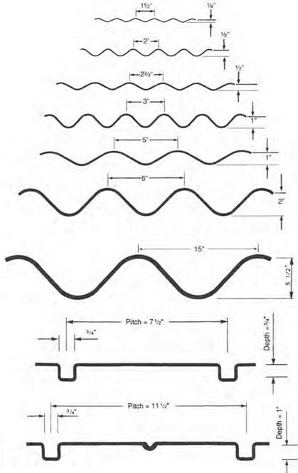
Numerous drainage products are available in steel with protective coatings and in aluminum. These include corrugated pipe, spiral-rib pipe, structural-plate pipe, box cul­verts, and, where a tunnel is required, tunnel liner plates. Figure 5.24 shows the variety of profiles available for the wall cross-section of steel drainage products. For additional profiles, see “Corrugated Steel Pipe Design Manual,” National Corrugated Steel Pipe Association, 2008. The arc-and-tangent profiles shown with depths of through 1 in (6.5 through 25 mm) are wall profiles for pipe factory-corrugated to the full pipe

Steel and Aluminum Pipe

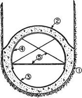
FIGURE 5.23 Cross-section of cast-in-place con­crete pipe showing form components. (From Lynch Manual, Cast-in-Place Concrete Process, W. M. Lynch Co., Dixon, Calif., 1990, with permission)

cross-section. The 2-in-deep (51-mm) profile, which is used for structural-plate pipe and box culverts, is corrugated and curved into arc segments that can be bolted together in the field. The 552-in-deep (140-mm) profile is a similar product used for longer-span structures. The 54- and 1-in-deep (19- and 25-mm) rectangular profiles are for factory-corrugated spiral-rib pipe. Figure 5.25 illustrates the shapes of the products, the range of sizes available in steel, and common uses. Some corrugation profiles and size ranges vary for aluminum products. The larger sizes of structural-plate products and box culverts in steel or aluminum are often used as replacements for short-span bridges. Factory-made box culverts are available in spans up to 26 ft (7.8 m) and even longer with special designs.

Corrugated Steel. Most of the metal pipes used are corrugated from coils of coated sheet steel. Coatings, which are applied by the continuous hot-dip process in the production of the steel coil, include zinc (galvanizing) and aluminum. In addition, coils are available precoated with a polymer (on one or both sides) to provide extra protection against corrosion and/or abrasion. Most corrugated pipes have a continuous helical lockseam, but some manufacturers use a continuous helical welded seam, or a longitudinal riveted or spot-welded seam. Wall profiles from 1/2 X ^4 in (38 X 6.5 mm) to 5 X 1 in (125 X 25 mm) are factory-corrugated to the full pipe cross-section. The pipe is furnished in lengths (typically 20 ft or 6 m) and joined in the field by coupling bands. Diameters through 120 in (3000 mm) are available, depending on the wall profile. Pipe-arch shapes for installations with low cover are formed to shape from lengths of round pipe.

Corrugated Aluminum. Corrugated aluminum pipe is usually furnished with one of the following wall profiles: 152 X 34 in (38 X 6.5 mm), 253 X 52 in (68 X 13 mm), or 3 X 1 in (75 X 25 mm). The pipe may have a helical lockseam or a riveted seam. It is furnished in lengths similar to steel pipe and joined in the field by coupling bands. Diameters through 120 in (3000 mm) are available, depending on the wall profile, and pipe-arch shapes are formed to shape from lengths of round pipe.

Spiral-Rib Pipe. This is a newer type of steel pipe that is helically corrugated to the rectangular profiles shown in Fig. 5.24. The cross-section profile has been developed so

Steel and Aluminum Pipe

FIGURE 5.24 Profiles for corrugated steel pipe and spiral-rib pipe. Conversion: 1 in = 25.4 mm. (From Handbook of Steel Drainage and Highway Construction Products, American Iron and Steel Institute, 1994, with permission)

Shape

Range of Sizes

Common Uses

Round

©

6 in.-26 ft (150 mm-7.9 m)

Culverts, subdrains, sewers, service tunnels, etc. All plates same radius. For medium and high fills (or trenches).

Vertical ellipse 5% nominal

0

4-21 ft (1.2-6.4 m) nominal: before elongating

Culverts, sewers, service tunnels, re­covery tunnels Plates of varying radii, shop fabrication. For appearance and where backfill compaction is only moderate

Pipe-arch

Span

~T

Rise

LL

Span x Rise 17 in. x 13 in. (430 x 330 mm) to

20 ft 7 in. x 13 ft 2 in.

(6270 x 4010 mm)

Where headroom is limited. Has hydraulic advantages at low flows. Corner plate radius, 18 in (457 mm) or 31 in (787 mm) for structural plate.

Underpass’

P

l-Span-n

1

Rise

*

Span » Rise 5 ft 8 in x 5 ft 9 in­to

20 ft 4 in x 17 ft 9 in.

For pedestrians, livestock or vehicles (structural plate)

. . Rise Arch ( Г

1-—Span -|

Span x Rise 6 ft x 1 ft 91/2 in. (1.8 x 0.55 m) to

25 ft x 12 ft 6 in. (7.6 x 3.8 m)

For low clearance large waterway open­ing. and aesthetics (structural olate)

Horizontal / Ellipse P

— Span—>

Span 7-40 ft (2.1-12 m)

Culverts, grade separations, storm sewers, tunnels.

Pear

0 —Span —

Span 25-30 ft (7.6-9.1 m)

Grade separations, culverts, storm sewers, tunnels.

High Profile i Arch

______________ l

— Span —-

Span 20-45 ft (6.1-14 m)

Culverts, grade separations storm sewers, tunnels Ammunition magazines, earth covered storage.

Low Profile / Arch 4

■ Span ■

|r

Span 20-50 ft

(6.1-15 m)

Low-Wide waterway enclosures, culverts, storm sewers.

Во» Culverts

cn

– Span —4

Span 8-26 ft (2.4-7.9 m)

Low-wide waterway enclosures, culverts, storm sewers

Specials

Various

For lining old structures or other special purposes. Special fabrication.

‘For equal area or clearance, the round snape is generally more economical and simpler to assemble

FIGURE 5.25 Shapes, range of sizes, and common uses of corrugated steel drainage products. Conversions: 1 in = 25.4 mm, 1 ft = 0.305 m. (From Handbook of Steel Drainage and Highway Construction Products, American Iron and Steel Institute, 1994, with permission)

that flow characteristics are similar to that of a smooth-walled pipe. It is available in either coated steel or aluminum, as either round pipe through 108-in (2700-mm) diameter, or as pipe-arch.

Structural-Plate Pipe. This product type is available in either zinc-coated steel or aluminum.

Steel. The 6- X 2-in (152- X 51-mm) profile used for structural-plate pipe and box culverts is corrugated and curved into arc segments. The segments provide an arc length of up to about 86 in (2184 mm), in lengths of 10 or 12 ft (3.0 to 3.7 m). The segments are joined together with high-strength bolts in a sequential manner during construction. All of the shapes illustrated in Fig. 5.25 can be constructed with this product. The 15- X 5L-in (381- X 140-mm) profile can be used for the larger struc­tures. With spans up to about 50 ft (15 m), structural-plate structures can provide an economical alternative for replacing short-span bridges. Field coatings can be applied to enhance durability.

Aluminum. The 9-in-wide (230-mm) by 2i2-in-deep (64-mm) profile is used for the aluminum structural-plate pipe and box culvert structures. Product characteristics are generally similar to those of the steel product.

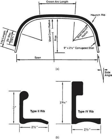
Long-Span Structures. Long-span structural-plate structures are defined as having either special shapes that involve a relatively large radius in the crown or side plates, or a span that exceeds certain structural design criteria as specified in AASHTO Standard Specifications for Highway Bridges. These structures generally have spans in the range of 20 to 50 ft (6 to 15 m). They are advantageous where headroom is restricted and can often provide the required waterway area at a lower cost than building a short-span bridge. Long-span structures are made up of a structural-plate barrel of coated steel or aluminum and integral special features that enable the structure to reach long spans. Special features include either (1) continuous longitudinal stiffeners of metal and/or reinforced concrete attached to the plates at the sides of the top arc, or (2) circumferential reinforcing ribs curved from structural shapes and attached to the plates to provide additional stiffness. Typical sections of each are illustrated in Fig. 5.26. They may be constructed to most of the shapes shown in Fig. 5.25 except box culverts.

Box Culverts. This product type is available in either zinc-coated steel or aluminum.

Steel. Box culverts are available in three types, including (1) 6- X 2-in (152- X 51-mm) corrugated plate shell with 6- X 3-in (152- X 76-mm) corrugated rib stiffeners (inside, outside, or both), (2) 6- X 2-in (152- X 51-mm) corrugated plate shell with 3- X 5-in (76- X 127-mm) hot rolled angle rib stiffeners, and (3) 15- X 5.5-in (381- X 140-mm) corrugated plate shell without stiffeners. Sizes range as shown in Fig. 5.25. The structures usually have an open bottom and are supported on a base channel or corrugated footing pads, on either a concrete footing or compacted soil, depending on size and other factors. They are also available with full invert plates.

Aluminum. Box culverts have a 9- X 2i2-in (230- X 64-mm) corrugated shell plate with extruded bulb angle rib stiffeners. Size ranges are similar to those for steel box culverts. Figure 5.27 shows a typical section and rib cross-sections. Stronger ribs, including a box-section rib, are available.

Tunnel Liners. Tunnel liners are press-formed from steel in an arc segment 16 or 18 in (400 or 450 mm) long. A corrugated profile is pressed in to make the wall cross­section, and flanges are formed on the sides. Two styles are available: (1) two-flange plates that are bolted through the flanges on the two longitudinal sides and lap-bolted

Подпись: Symmetrical about £

Steel and Aluminum PipeConcrete Thrust Beam

Thrust Beam to be made integral with Headwall

Span

Подпись: Symmetrical about <£Structural member attached to structural

plate corrugation

Staggered joints except at radius change

Span

FIGURE 5.26 Typical sections of long-span structural-plate structures. (a) Longitudinally stiffened with concrete thrust beam. (b) Transversely stiffened with structural members. (From Highway Design Manual, California Department of Transportation, with permission)

on the other two sides, and (2) four-flange plates that are bolted together through flanges on all four sides. Installation and assembly can be done entirely from the inside as the tunnel is constructed. The assembled liner plates may then act as a tem­porary structure that is lined by concrete, or may act alone as a permanent conduit. In addition to tunneling, the liner plates can be used in rehabilitation work, such as for lining a deteriorated culvert.

Steel and Aluminum Pipe

FIGURE 5.27 Corrugated aluminum box culvert. (a) Typical cross-section. (b) Details of stiffen­ing ribs. Conversion: 1 in = 25.4 mm. (From Aluminum Box Culverts, Contech Construction Products, with permission)

5.6.2 Plastic Pipe

Both high-density polyethylene (HDPE) and polyvinyl chloride (PVC) are used for drainage pipe. HDPE pipe may be single-wall corrugated, smooth-wall (double-wall), or ribbed. Common diameters are 4 to 24 in (100 to 600 mm) for single wall, 4 to 60 in (100 to 1500 mm) for double wall, and 18 to 96 in (450 to 2400 mm) for ribbed pipe. Single-wall pipe has a deep corrugation, whereas a smooth internal liner is added for double­wall pipe. Wall profile details vary with the manufacturer. PVC pipe may be either smooth-wall or ribbed, with diameters ranging up to 54 in (1350 mm). Plastic pipe is fur­nished in lengths (typically about 20 ft (6 m) for HDPE and 13 ft (4 m) for PVC) and joined in the field by coupling bands. It is available only as round pipe.

Electrical Wiring

Подпись: Use a wire stripper to strip 'h in. of insulation off the wire ends before attaching them to the screw terminals on switches. Begin by scoring the insulation with a twist of the wrist. Then use your thumb as a fulcrum to pop the insulation off.image462

Electrical work is among the most pre­dictable, pleasant aspects of construction—no heavy lumber to be wrestled, no large sheets that would fit if only your fingers weren’t in the way, no quick-drying compounds driving you into a frenzy. Wiring a house is methodical work that requires attention to detail and some dexterity. And you know quickly if you’ve done the work correctly: bulbs glow and radios play.

Electricity should be respected, and it must be taken seriously. But it is a natural phenomenon, subject to the laws of physics. If you heed the safety precautions in this chapter—especially those about shutting off power and testing with a voltage tester, to make sure the power is off— you’ll do fine. If you’re new to wiring, take the time to read the whole chapter because important information is not necessarily repeated.

It’s imperative that you check with local building code authori­ties even before buying tools and materials. Although most building authorities do not for­bid an owner’s doing his or her own electrical work, most require inspections when the system is roughed in—that is, before wires are connected to switches, receptacles, and so on. Besides, building inspectors are usually knowledgeable: They can tell you if local codes con­form to the National Electrical Code® (NEC) or, if not, how they vary.

If this chapter whets your appetite for more, get copies of

Rex Cauldwell’s Wiring a House (The Taunton Press) and Redwood Kardon, Doug Hansen, and Mike Casey’s Code Check® Electrical (The Taunton Press).

Understanding Electricity

Electricity is tricky to describe. A physicist might call it "the movement of electrons,” but most peo­ple find it easier to visualize electricity as some­thing like water flowing through a hose. Using that analogy, here are two useful concepts:

(1) Electrical current flows in a circle, making a circuit, and (2) it flows most easily along paths of least resistance, but it will follow any path that’s available. . . including you!

Fluctuations in Batching of Components

SMA mixtures are very susceptible to overbatching of the binder quantity during production. When this occurs, an extra amount of binder appearing in a mixture is followed by the rapid decrease of mastic consistency and a change in the volume ratios of the entire SMA. Moreover the risk of binder or mastic draindown becomes much higher.

The strength of SMA is founded on its mineral skeleton. So the properties of SMA are dependent on the gradation and, consequently, are extremely susceptible to the shifting of the gradation curve. As discussed in Chapter 6, we should consider the impact of the change of coarse aggregate content on the breakpoint (BP) sieve. Another way to express that concept is that a substantial change in the content of the largest coarse aggregates causes such significant changes to the volume relations of a mixture that they can greatly diminish an SMA’s strengths.

9.3.5 Systems of Batching Stabilizers

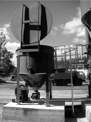
Modern asphalt plants are equipped with integrated silos—delivering and weighing systems mostly designed for granulated or pelletized stabilizers. These stabilizers are stored in silos and then transferred to the scales, proportioned by weight or by volume and blown by compressed air into the pugmill (Figure 9.7). In older plants,

image85

FIGURE 9.7 A system for batching granulated fibers into mixing plants. The photo­graph shows an open silo for granulates ready for loading. (Photo courtesy of Bartosz Wojczakowski.)

more or less sophisticated batching methods (i. e., proportioning by weight or by volume) are applied to weigh out or measure out a batch of granulated or loose fibers directly into the pugmill (Figure 9.8).

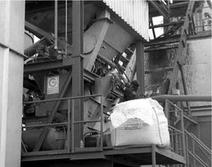
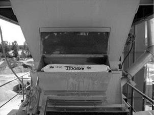
Automatic batching devices for nongranulated (loose fibers) are rare. Bags of loose fibers are emptied through a special charging box into the pugmill (Figure 9.9) or directly through an opening in the upper part of the pugmill’s cover.

image86

FIGURE 9.8 Manual proportioning control of a granulated stabilizer directly into the pug­mill. (Photo courtesy of Bartosz Wojczakowski.)

image87

FIGURE 9.9 Manual charging box with a motor-driven chute. (Photo courtesy of Bartosz Wojczakowski.)

When there are no bins for stabilizer, an effective solution may be the direct delivery of granulated cellulose fibers from a tanker into the pugmill.

Time-dependent load

In time-dependent reliability analysis, one is concerned with system reliability over a specified time period during which external loads can occur more than once. Therefore, not only the intensity or magnitude of load is important but also the number or frequency of load occurrences is an important parameter.

Over an anticipated service period, the characteristics of load to be imposed on the system could change. For example, when a watershed undergoes a pro­gressive change, it could induce time dependence in load. More specifically, the magnitude of floods could increase as urbanization progresses, and sediment discharge from overland erosion and non-point-source pollution could decrease over time if the farming and irrigation practices in the watershed involve pol­lution control measures. Again, characterization of the time-varying nature of load intensity requires extensive monitoring, data collection, and engineering analysis.

The occurrence of load over an anticipated service period can be classified into two cases (Kapur and Lamberson, 1977): (1) The number and time of occurrence are known, and (2) the number and time of occurrences are ran­dom. Section 4.7.4 presents probabilistic models for describing the occurrence and intensity of load.

Sampling of Runoff

Sampling can aim at documenting contaminant concentrations and fluxes during and after storm events (or other rain or snow melt), at mirroring the load and flux of contaminants over an extended period of time, or at characterizing an accidental discharge.

Road runoff presents specific characteristics that change significantly from place to place, depending on site characteristics and many other factors (Barbosa & Hvitved-Jacobsen, 2001). Therefore, the monitoring programme should also include the characterization of the most important factors such as: traffic characteristics (volume, speed, type of vehicles, fuel types, etc.), geographic location, climate, topography, drainage area and road design, pavement characteristics, right-of-way characteristics and adjacent land use. Although the quality of water is being in­fluenced by several external characteristics, it is the duration and intensity of the pavement washing that determines the degree of dilution and transport of pollutants. The site selected for runoff sampling should be a drainage area (with significant and representative size) where the runoff from the paved and unpaved areas can be isolated from other sources within the selected highway system.

Runoff sampling may be used to characterize the influence of the mean daily traffic of a road section. For that purpose samples must be collected in a discrete way, in a surface drainage pipe (e. g. Fig. 7.1), during rain or snow thawing events, and be associated with a specific road drainage area. The runoff flow measurement devices are usually installed transversally in the outflow pipe from the system drain­ing the area of pavement that is of interest and must include a calibrated component that links the observed water level to the corresponding runoff volume by knowing the shape and dimension of the pipe. Runoff sampling depends on the occurrence of precipitation, and therefore, sampling is facilitated by the use of sampling equip­ment that is activated by a sensing device which automatically starts the sampling whenever the flow rate exceeds a previously defined value. Such sampling equip­ment also has the benefit of allowing the sampling of the first flush of a storm event.

This type of monitoring gives discrete information about the changes in runoff pollution during a certain period and allows the determination of the Event Mean Concentration (EMC) and the Site Mean Concentration (SMC). An EMC is

calculated for an individual storm event as the total mass load of a pollutant parameter (CV) divided by the total runoff water volume (V) discharged during the storm (Hvitved-Jacobsen & Vollertsen, 2003):

EMC = ZCV/ZV (7.1)

A SMC is a characteristic runoff annual pollution loads for a specific site, typically defined by the arithmetic mean value of the EMC’s measured at one site (Hvitved – Jacobsen & Vollertsen, 2003).

To evaluate the EMC it is advisable to sample the whole event in a way that is time constant and volume proportional. In this method, discrete samples are col­lected at equal time increments and composed proportional to the varying flow rate during the sampling period (FHWA, 1987, 1988). In order to mirror seasonal varia­tions, a monitoring programme should, ideally, include several discrete storm events for a one-year period. Authors differ in their opinions about the minimum number of storm events needed. Some authors consider 10, others 6 storm event episodes, each one characterized by a minimum of 5 samples (Barbosa, 1999, Burton & Pitt, 2002). Probably, the choice is influenced by storm severity and other climatological factors that may vary widely between countries and regions.

To allow the characterization of road runoff throughout a specific period, runoff monitoring devices should be:

• automated;

• include a rainfall device;

• include a runoff flow measurement device; and

• include sampling and recording equipment.

All these devices should operate in phase with each other in order to allow the determination of lag time from rainfall to runoff and the determination of pollutant load in each sample.

Figure 7.2 illustrates an alternative approach, common for measuring lower flow volumes than observed in runoff collection pipes – e. g. rainfall and seepage water. Water is fed into a bucket (Fig. 7.2a) that tips alternately to left and right when it fills. The number of tips may be counted electronically. Figure 7.2b shows a typical installation, in this case with the possibility of some of the water being sampled for later analysis. By integrating the output of the tipping buckets with the automatic water sampling equipment (as shown in Fig. 7.3) it is possible to sample water on a volumetric basis rather than a time basis.

Where discrete sampling is not feasible, runoff sampling can be accumulative. For that it is possible to arrange special sampling devices, in the form of a gutter installed along the sealed pavement’s edge to capture runoff water and then to con­duct it to a type of tank, such as a rainwater settling tank or a retention tank installed close to or away from the road. Afterwards the tank can be sampled by abstracting a proportion into a vessel installed in a chamber dug into the roadside soil. These devices can give a broad idea about the road pollution but are not appropriated for load calculations if their draining section is not easily delineable. These sampling
methods are less informative since they give information about the road pollution integrated over a period of time. Also, other sources than the road and its traffic might contribute to the contaminants collected in the tanks. Furthermore, change in water condition can take place between the time that water arrives at the tank and the time at which a specimen is collected. Sampling from tanks, therefore, only gives a qualitative overview of road pollution. In the case of an overall sample taken in

Fig. 7.3 Automatic water sampler with refrigerated cabinet (Courtesy of Hach. ©Hach Company, 2007)

a settling tank or retention tank, water collection must be made at several locations and depths of the tank so as to provide a composite sample representative of the water in the entire tank.

CULVERT TYPES AND MATERIALS

The main types of pipe used in highway construction are concrete pipe, metal pipe (steel or aluminum), and plastic pipe (high-density polyethylene and polyvinyl chloride). They are available in a wide array of sizes, shapes, and properties. Table 5.10 gives the ASTM and AASHTO standards for the most common highway drainage pipes. Some of the characteristics of these pipes are reviewed below.

5.6.1 Concrete Pipe

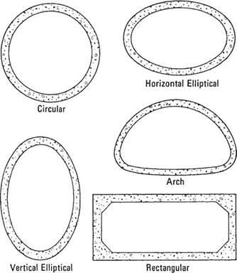
Concrete pipe is manufactured as nonreinforced, reinforced, or cast-in-place pipe; as box culverts and special shapes; and as field-constructed pipe. Shapes, as shown in Fig. 5.21, include round, horizontal and vertical ellipse, and arch configuration.

Factory-Made Pipe. Nonreinforced pipe is used for smaller diameters, whereas pipe with steel reinforcement is used for larger diameters and greater loads. Both are manu­factured in a plant, cured, and shipped to the job site. They are furnished in relatively short lengths and coupled with a bell-and-spigot or tongue-and-groove type joint.

Nonreinforced concrete pipe is available in diameters from 4 to 36 in (100 to 900 mm) and three strength classes. Nonreinforced concrete pipe is available as round pipe only. Reinforced concrete pipe is available in diameters from 12 to 144 in (300 to 3600 mm). The strength of reinforced concrete pipe can be specified according to five standard pipe classes (ASTM C 76), with Class I pipe being the most economical and Class V offering the greatest structural strength; according to required D-load strength (ASTM C 655); or according to a direct wall design (ASTM C 1417). Wall thickness of reinforced concrete pipe can be varied to meet in-field conditions. The standard “class” specifications for pipe give wall thickness according to three distinct types, which vary from Wall A, being the thinnest, to Wall C, being the thickest.

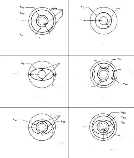
Steel reinforcing for reinforced concrete pipe can be arranged in many combina­tions to meet the given structural requirements. Figure 5.22 shows some of the steel reinforcement layouts used in manufacturing reinforced concrete pipe.

Cast-in-Place Pipe. This type of nonreinforced pipe is formed in a trench using a continuous process. First a trench is excavated so that it has a semicircular bottom and vertical or near vertical sidewalls, which serve as the outer form for the bottom and sides. The upper portion of the pipe is cast against an inner arch form as illustrated in Fig. 5.23. The form is pulled along the trench while concrete is poured into a hopper

TABLE 5.10 Standards for Common Drainage Pipes

Type of pipe

ASTM Standard

AASHTO Standard

Vitrified clay pipe

Vitrified clay pipe

C 700

M 65

Concrete pipe

Nonreinforced, circular

C 14, C 985

M 86

Reinforced, circular

C 76, C 655, C 1417

M 170

Reinforced, elliptical

C 507

M 207

Reinforced, arch

C 506

M 206

Reinforced, box

C 1433

M 259, M 273

Reinforced, three-sided

C 1504

Corrugated steel pipe

From metallic-coated sheet

A 760

M 36

From zinc-coated structural plate

A 761

M 167

From polymeric-coated sheet

A 762

M 245

Postmanufacture applied coatings

A 849, A 862

M 190

Box culverts

A 964

Corrugated aluminum pipe

From sheet

B 745

M 196

From structural plate

B 746

M 219

Box culverts

B 864

Plastic pipe

PVC (polyvinyl chloride)

D 1785

PVC

D 2665

PVC

D 3034

PVC

F 679

PVC

F 789

PVC

F 891

PVC

F 949

PVC

M 304

ABS PVC composite

D 2680

M 264

ABS (acrylonitrile-butadiene-styrene)

D 2661

ABS

D 2751

PE (polyethylene)

F 405

PE

F 667

PE

F 714

PE

F 892

PE

F 894

PE

M 252

PE

M 294

located above. Powered spading mechanisms and variable-speed vibrators aid the flow of the concrete.

Box Culverts. Box culverts are rectangular shapes with flat sides, top, and bottom. These shapes are constructed with steel reinforcement. Factory-made boxes are shipped in sections 4 to 8 ft (1200 to 2400 mm) long and joined in the field to make a structure of the required length.

Precast Three-Sided Culverts. Three-sided culverts, sometimes called “three-sided box culverts,” are rectangular in shape. These shapes are constructed with steel reinforcement

CULVERT TYPES AND MATERIALS

FIGURE 5.21 Concrete pipe is manufactured in five common shapes; regional custom and demand usually determine availability. (From Concrete Pipe Handbook, American Concrete Pipe Association, 1988, with permission)

that may or may not be pretensioned. They are available in spans between 12 and 34 ft (3.7 and 10.4 m), and rises up to 10 ft (3 m). These structures usually have an open bottom and are constructed on concrete footings.

Special Shapes. Other shapes are also manufactured. One example is a reinforced concrete section made up of an arch top and vertical sidewalls. Another example is a reinforced concrete arch that can be fabricated in either one or two piece segments. Both examples are joined in the field to make up the required length. With spans of 12 to 84 ft (3.7 to 25 m) or larger they are suitable as replacement structures for short span bridges. Additionally, segmental tunnel liners can be furnished as precast concrete segments.

Field-Constructed Pipe. Large reinforced structures may be constructed at the job site using appropriate formwork. Large arches and box culverts are often constructed in this manner.

Подпись: Double Circular Cage + Elliptical Cage

CULVERT TYPES AND MATERIALS CULVERT TYPES AND MATERIALS
Подпись: Crown
Подпись: Crown Cover over
Подпись: Cover over
Подпись: invert
Подпись: Invert
Подпись: Springiine
Подпись: Springiine
Подпись: Angle of

Подпись: Single Elliptical Cage

Подпись: Springiine
Подпись: invert Подпись: Invert

Подпись: Invert Mat Reinf

Подпись: Crown Cove( Qver Подпись: Crown CULVERT TYPES AND MATERIALS
CULVERT TYPES AND MATERIALS
Подпись: Single Circular Cage
Подпись: Crown
Подпись: Crown
Подпись: Springiine
Подпись: Cover over Reinf. __
Подпись: Springiine
Подпись: Springlme
CULVERT TYPES AND MATERIALS
Подпись: nvert
Подпись: Invert
Подпись: Crown Mat Reinf
Подпись: Springiine
Подпись: Springiine

CULVERT TYPES AND MATERIALSFIGURE 5.22 Concrete pipe culvert reinforcement notation. (From PIPECAR: User and Programmer Reference Manual, FHWA, 1989, with permission)
Discharge Velocity and Energy Dissipation

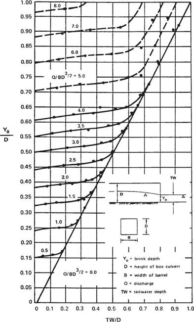
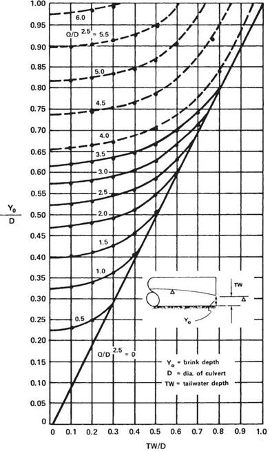
Because of its hydraulic characteristics, the outlet velocity of a culvert is usually higher than the velocity in the discharge channel. The outlet velocity may be calculated either using Manning’s equation, Eq. (5.11), if the culvert is under inlet control, or by divid­ing the discharge by the cross-sectional area of the flow if under outlet control. Under outlet control, if the tailwater is above the crown of the pipe, or if the discharge is high enough to result in a critical depth equal to the depth of the culvert barrel, then the flow area may be taken as the area of the barrel. If the tailwater depth is low, the area of flow, and thus the velocity, may be determined using the chart in Fig. 5.19 or 5.20. To use these charts, first calculate the normal depth or tailwater TW (ft) in the channel; the ratio TW/D, where D is the structure height (ft); and the flow parameter Q/BD3/2, where B (ft) is the width of the barrel and Q (ft3/s) is the discharge. Enter the chart with TW/D and find YJD at the intersection of the appropriate curve. Multiply by D to determine the depth of flow at the outlet end of the culvert, Yo. The flow area is then calculated for Yo and the velocity for the flow Q from the continuity equation, Eq. (5.10). o

Recommended maximum channel velocities were presented in Table 5.5. The velocity at the outlet should be kept at or below these values, or, if this is not possible, the channel should be protected from erosion. The controlling parameters for the cul­vert velocity are its slope and roughness. If the recommended velocity is exceeded, consider decreasing the slope or using a culvert with a greater roughness coefficient.

Discharge Velocity and Energy Dissipation

Discharge Velocity and Energy Dissipation

If the velocity at the outlet cannot be reduced by these means, channel protection or energy dissipaters should be used to protect against erosion. Channel protection may consist of treatments such as concrete aprons or cutoff walls. In some cases, concrete or rock riprap may be required. These types of protection do not necessarily dissipate the energy, but protect against erosion. Energy-dissipating devices may be necessary either separately or in conjunction with channel protection where flow velocities are high. Dissipation devices, if used, are generally located at the outlet end or in the inte­rior near the end of the culvert. If such devices are used, consideration must be given to the effects on possible debris collection. (See “Hydraulic Design of Energy Dissipators for Culverts and Channels,” HEC 14, FHWA.)