AND GROUND FAULTS
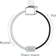
Electricity moves in a circle from power source back to power source, whether it travels across the country in great transmission lines or flows through the cables in your walls. In a house, each distinct electrical loop is called a circuit.
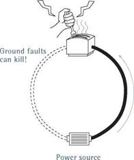
Most of the time, household electricity flows through copper wires (low resistance) insulated with thermoplastic or rubber (very high resistance). But electrical current is opportunistic. Should a wire’s insulation break and a fault circuit of lesser resistance become available, current will flow through it. The current flowing through that fault circuit is called a ground fault. The lower the fault circuit’s resistance, the greater that current flow will be.
If equipment and appliances are correctly grounded (bonded together), this abnormally high current flow (amperage) will trip a breaker or blow a fuse, cutting power to the fault circuit—or "clearing the fault,” as electricians say.
A modern electrical system consists of three large cables, or conductors, which may enter the house overhead or underground. When fed underground, service conductors are installed in buried conduit or run as USE (underground service entrance) cable. Overhead service running from a utility pole typically consists of a triplex assembly—two insulated hot conductors wrapped around a bare messenger cable that also serves to carry the neutral load—which runs to a weather head atop a length of rigid
PLAY IT Safe
Only a licensed electrician should work in a service panel—or remove its cover. Even with the main fuse or breaker turned off, some of the cables inside a panel are always hot (carrying electricity) and could electrocute you.
So could hot wires touching the sides of an incorrectly wired panel. Don’t mess with electric meters, either: Call the utility company to install meters or upgrade incoming service.
![]()
![]()
 To work safely on existing circuits, always disconnect electrical power at the service panel, and use a voltage tester (see the photos on p. 235) at the outlet to verify that the power’s off. Throughout this chapter (and book), you’ll see this symbol as a reminder:


 |
 |
conduit. (Overhead service cables are called a service drop.) Whether it arrives overhead or underground, three-wire service delivers 240 volts. An old service with only two incoming wires—one hot and one grounded neutral conductor—delivers only 120 volts, which is inadequate for modern household demand and so should be upgraded.
Service conductors attach to a meter base. From the meter base runs another length of rigid conduit, or service entrance (SE) cable, to the service panel. Straddling the two sets of terminals on its base, the meter measures the wattage of electricity as it is consumed. (Increasingly common are meter-main combos, which house a meter base and a main service panel in a single box.)
Main service panel. At the main service panel, the two hot cables from the meter base attach to
lug terminals atop the main breaker, and the incoming neutral cable attaches to the main lug of the neutral/ground bus, as shown in "Main Service Panel, Unwired,” below. In main service panels, neutral/ground buses must be bonded, usually by a main bonding jumper. Important:
In subpanels and all other locations downstream from the main service panel, ground and neutral buses must be electrically isolated from each other.
In a service fuse box, the hot cables attach to the main power lugs, and the neutral cable to the main neutral lug. Whether the panel has breakers or fuses, metal buses issue from the bottom of the main breaker/main fuse. Running down the middle of the panel, buses distribute power to the various branch circuits. Similarly, neutral/ground buses are long aluminum strips with many screws that ground and neutral wires attach to.

 THE Main BREAKER
All electricity entering a house goes through the main breaker, which is usually located at the top of a main panel. In an emergency, throw the main breaker switch to cut all power to the house.
The main breaker is also the primary overcurrent protection for the electrical system and is rated accordingly. (The rating is stamped on the breaker handle.) Thus if the main breaker for a 200-amp panel senses incoming current that exceeds its overload rating, the breaker will automatically trip and shut off all power.
Each fuse or breaker is rated at a specific number of amperes (amp), such as 15 or 20. When a circuit becomes overloaded, its current flow becomes excessively high, causing its breaker to trip or its fuse strip to melt, thereby cutting voltage to the hot wires. All current produces heat, but as current doubles, the heat generated quadruples. If there were no breakers or fuses, current would continue flowing till wires overheated and a fire started. Thus the amperage ratings of breakers and fuses are matched to the size (cross-sectional area) of the circuit wires.
Branch circuits. Branch circuits are conductors that run from the last overcurrent device (fuse or breaker) to their outlets. Inside each cable or conduit are several wires color-coded for safety.
In most 120-volt circuits, there is one hot wire (coded black), one neutral wire (coded white), and one bare copper (or green) ground wire. Think of hot and neutral wires as parallel wires that must never be joined.
Ground wires (discussed later in this chapter) must also be kept separate from hot and neutral wires as you run branch circuits. (Ground and neutral bus bars are connected in the main panel, but that’s another issue.) In 240-volt circuits, such as those “dedicated” to a heavy user like a stove, there are typically two hot wires: one coded black, and the other, red.
Outlets. Each branch circuit serves one or more outlets. At outlets, individual wires connect to various devices such as switches, receptacles, and fixtures. To ensure a safe hookup, the devices’ connecting screws or terminals are color coded or otherwise clearly designated: Hot wires attach to gold – or brass-colored screws, neutral wires to silver screws, and ground wires to green screws (when present).
Switches cut or vary the flow of power by interrupting hot lines only. Neutral wires are always
continuous, as are ground wires, even though their sections may be connected by wire nuts. Wire nuts are insulated caps that twist onto the bare ends of wire splices (clusters), thereby joining them mechanically and covering them so those bare ends can’t come in contact with other wires, devices, fixture terminals, or the outlet box itself.
A house’s grounding system is complex, and understanding it is made more difficult by the imprecise language used to describe it—as noted in “Making Sense of Grounding,” on p. 230. If you want a more comprehensive overview of grounding, get a copy of the book Code Check® Electrical, mentioned earlier. Here are some of the basics.
Underlying principles. Fuses were among the earliest overcurrent devices, and they greatly reduced the incidence of electrical fires by disconnecting current when its flow became too great. But something more was needed to protect people, who were being electrocuted when they came in contact with fault currents unintentionally energizing the metal casing of a tool or an electrical appliance, for example.

![]()
 Consequently, the industry added equipmentgrounding conductors (which we’ll call ground wires) that bond all electrical devices and potentially current-carrying metal surfaces. This bonding creates a path with such low impedance (resistance) that fault currents zip along it as they return to the power source—quickly tripping breakers or fuses, and clearing the fault. Contrary to popular misconceptions, the human body has a relatively high impedance (compared to copper wire), so if electricity is offered a path of less resistance (a copper ground wire), it will take it.
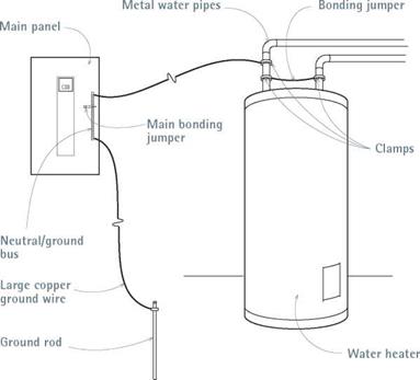
To sum up: To reduce shock hazards, individual ground wires connect to every part of the electrical system that could become a potential conductor—metal boxes, receptacles, fixtures— and, through three-pronged plugs, the metallic covers and frames of tools and appliances. At the main service panel, these ground wires attach to a neutral/ground bus bar, which is itself bonded to the metal panel via a main bonding jumper.
To quote one master electrician, "This bonding jumper is possibly the most important single connection in the whole system.”
Grounding electrode system. Also attached to the neutral/ground bus in the service panel is a large, bare copper ground wire —the grounding electrode conductor (GEC)—that clamps to a grounding electrode (also called a ground rod), which is driven into the earth or is attached to steel rebar in the footing of a foundation. The electrode’s primary function is to divert lightning
and other outside high voltages before they can damage the building’s electrical system.
Note: Although the grounding electrode system (GES) is connected to the equipmentgrounding system at the service panel, the GES has virtually nothing to do with reducing shock hazards.
The NEC sizes grounding electrode conductors based on the sizes and types of conductors in the service. Typically, residential GECs are size 6 American Wire Gauge (6AWG) copper. Ground rods are typically 58-in. to 54-in. copper-clad steel rods 8 ft. to 10 ft. long; the longer the rod, the more likely it will reach moist soil, whose resistance is less than that of dry soil. Be sure to install multiple-rod systems in lightning-prone areas.
GROUND-FAULT CIRCUIT INTERRUPTERS
Despite the presence of grounding systems, people were still being killed by electrical shock, particularly when moisture was present. To remedy this problem, the industry developed ground-fault circuit interrupters (GFCIs), which are highly sensitive devices that can detect minuscule current leaks and shut off power almost instantaneously. A ground fault is any failure of the electrical system that leaks current from a hot wire.
Normally, the current in hot and neutral wires is identical. But when there is as small a variance as 0.005 amp (5 milliamperes) between hot and neutral wires, a GFCI can shut off all power within 540 of a second. Consequently, the NEC now requires GFCI protection on all bathroom receptacles, kitchen receptacles within 4 ft. of a sink, all receptacles serving kitchen counters, all outdoor receptacles, accessible basement or garage receptacles, and receptacles near pools, hot tubs, and the like.
A GFCI breaker will cut all power to a circuit, whereas a GFCI receptacle will cut power to receptacles downstream if wires are fed through the GFCI receptacle as shown in "Wiring a GFCI Receptacle,” on p. 250.
When electrical connections are loose or corroded or if nails puncture wires, electricity can arc (jump) between points. Arcing may be responsible for many of the 40,000 electrical fires each year. The NEC now requires arc-fault circuit interrupter (AFCI) protection for all 15-amp and 20-amp bedroom circuits. Just as GFCIs cut power to prevent shocks, AFCIs detect minute fluctuations in current associated with arcing
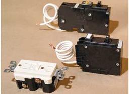
 Electrical safety devices. From fop:arc-fault circuit interrupter (AFCI) breaker, ground-fault circuit interrupter (GFCI) breaker, and GFCI receptacle.
and de-energize the circuits before a fire can start. Installing AFCI breakers is essentially the same as that for GFCI circuit breakers.


Leave a reply