Category PLUMBER’S AND. PIPE FITTER’S. CALCULATIONS MANUAL

PIPE THREADS

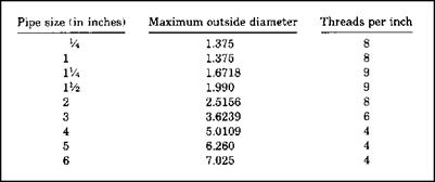
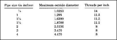
Pipe threads come in different styles. Some are compatible, and others are not. You could encounter straight pipe threads, tapered pipe threads, or fire­hose coupling straight threads. To understand the types of pipe and hose threads, let me give you some illustrations to consider. The tables in Figures 11.11, 11.12, and 11.13 show you how many threads per inch to expect with different thread types. Fire hose threads are not compatible with any other type of threads. The same is true for garden hose threads. But, some threads are compatible with other types. If you have a female NPT thread pattern, it is compatible with male threads of an NPT type. The proper sealant to mate these threads is a thread seal. American Standard Straight Pipe (NPSM) threads on female threads can be mated to either NPSM male threads or NPT male threads. To seal such a connection, a washer seal should be used.

PIPE THREADS

FIGURE 11.11 ■ Threads per inch for national standards.

PIPE THREADS

FIGURE 11.12 ■ Threads per inch for American Standard Straight Pipe.

PIPE THREADS

FIGURE 11.13 ■ Threads per inch for garden hose.

Female threads that are NPSH can be coupled with male threads of NPSH, NPSM, or NPT types. In any of these cases, a washer seal should be used. Threads of a garden hose type are mated with a washer seal. But, what happens when you are trying to find compatible matches for a male thread pattern? If you have an NPT male thread, it can be mated to NPT, NPSM, or NPSH threads. When NPT is mated to NPT, a thread sealant should be used. Washer seals are used to mate NPSM or NPSH female threads to male NPT threads. A male NPSM thread can mate with female thread types of NPSM or NPSH. A washer seal should be used for these connections. Garden hose threads, whether male or female, can only be coupled to garden hose threads, and this is done with a washer seal.

THERMAL EXPANSION

Thermal expansion can occur in pipes when there are temperature fluctua­tions. Damage can result from this expansion if the pipe is not installed prop­erly. In order to avoid damage, refer to Figures 11.7, 11.8, and 11.9 to learn about the tolerances needed for various types of pipe (Fig. 11.10).

THERMAL EXPANSION

Coefficient

Pipe material

in/in/°F

(°С)

Metallic pipe

Carbon steel

0.000005

(14.0)

Stainless steel

0.000115

(69)

Cast iron

0.0000056

(1.0)

Copper

0.000010

(1.8)

Aluminum

0.0000980

(1.7)

Brass (yellow)

0.000001

(1.8)

Brass (red)

0.000009

(1.4)

Plastic pipe

ABS

0.00005

(8)

PVC

0.000060

(33)

PB

0.000150

(72)

PE

0.000080

(14.4)

CPVC

0.000035

(6.3)

Styrene

0.000060

(33)

PVDF

0.000085

(14.5)

PP

0.000065

(77)

Saran

0.000038

(6.5)

CAB

0.000080

(14.4)

FRP (average)

0.000011

(1.9)

PVDF

0.000096

(15.1)

CAB

0.000085

(14.5)

HDPE

0.00011

(68)

Glass

Borosilicate

0.0000018

(0.33)

FIGURE 11.7 ■ Thermal expansion of piping materials. (Courtesy of McGraw-Hill)

Temperature Change (°F)

Length (ft)

40

50

60

70

80

90

100

20

0.278

0.348

0.418

0.487

0.557

0.626

0.696

40

0.557

0.696

0.835

0.974

1.114

1.235

1.392

60

0.835

1.044

1.253

1.462

1.670

1.879

2.088

80

1.134

1.392

1.670

1.879

2.227

2.506

2.784

100

1.192

1.740

2.088

2.436

2.784

3.132

3.480

Подпись: Temperature Change (°F) Length (ft) 40 50 60 70 80 90 100 20 0.536 0.670 0.804 0.938 1.072 1.206 1.340 40 1.070 1.340 1.610 1.880 2.050 2.420 2.690 60 1.609 2.010 2.410 2.820 3.220 3.620 4.020 80 2.143 2.680 3.220 3.760 4.290 4.830 5.360 100 2.680 3.350 4.020 4.700 5.360 6.030 6.700

FIGURE 11.9 ■ Thermal expansion of all pipes (except PVC-DWV). (Courtesy of McGraw-Hill)

Подпись: A hole in a pipe that is not more than .63 centimeters in diameter can result in a loss of 14,952 gallons of water a day! Even a pinhole leak can amount to a loss of over 18,000 gallons of water in a three-month period.

FIGURE 11.10 ■ Tech tips.

FIGURING THE WEIGHT OF A PIPE

Figuring the weight of a pipe and its contents is necessary when you are choosing the needed strength of a pipe hanger. There is a formula that you can use to accomplish this goal. Let’s say that you want to know how much a

Nominal pipe size (NPS), in IP

ASHRAE std. wt. size, mm

AWWA pipe size, mm

NFPA pipe size, mm

ASTM copper tube size, mm

Nominal

pipe

size DN, mm

Vs

_

в

6

3/ie

8

8

У4

8

10

10

%

10

12

12

y2

15

12.7 & 13

12

15

15

%

18

18

3/4

20

22

20

1

25

25

25 & 25.4

28

25

Г/4

32

33

35

32

1У2

40

45

38 & 38.1

42

40

2

50

50 & 50.8

51

54

50

2Уг

65

63 & 63.5

63.5 & 64

67

65

3

80

75

76 & 80

79

80

ЗУ2

89

90

4

100

100

102

105

100

4У2

114.3

115

5

127

130

125

6

150

150

152

156

150

8

200

200

203

206

200

10

250

250

257

250

12

300

300

305

308

300

14

350

350

18

400

400

18

450

20

500

500

24

600

600

28

700

30

750

32

800

36

900

40

1000

44

1100

48

1200

52

1300

56

1400

60

1500

FIGURE 11.2 ■ Equivalent metric (SI) pipe sizes. (Courtesy of McGraw-Hill)

piece of pipe weighs. You will need some information, which can be found in Figure 11.5. And, you will need the formula, which is as follows:

W = F X 10.68 X T X (O. D. – T)

You’re probably wondering what all the letters mean, and you should be. I’ll tell you. The letter W is the weight of the pipe in pounds per foot. A relative

Nominal rod diameter, in

Root area of thread, in2

Maximum safe load at rod temperature of 650°F, lb

Vi

0.027

240

s/ie

0.046

410

%

0.068

610

Vi

0.126

1,130

%

0.202

1,810

3/4

0.302

2,710

%

0.419

3,770

1

0.552

4,960

lVs

0.693

6,230

lVi

0.889

8,000

1%

1.053

9,470

IVi

1.293

11,630

1%

1.515

13,630

13A

1.744

15,690

1%

2.048

18,430

2

2.292

20,690

2У«

3.021

27,200

2 Vi

3.716

33,500

2%

4.619

41,600

3

5.621

50,600

3Vi

6.720

60,500

ЗУ2

7.918

71,260

FIGURE 11.3 ■ Load ratings of threaded rods. (Courtesy of McGraw-Hill)

Pipe size, in

Rod size, in

2 and smaller

3/8

2Vi to 3Vi

Vi

4 and 5

5/«

6

3/4

8 to 12

%

14 and 16

1

18

lVfe

20

Г/4

24

IVi

FIGURE 11.4 ■ Recommended rod sizes for individual pipes. (Courtesy of McGraw-Hill)

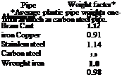
weight factor, which can be found in Figure 11.5, is represented by the letter F. Wall thickness of a pipe is known as the letter T. You have probably guessed that O. D. represents the outside diameter of the pipe, in inches. I said that you could figure out the weight of pipe and its contents. To determine the weight of water in pipe, refer to Figure 11.6.

FIGURING THE WEIGHT OF A PIPE
Подпись: been there done that As a young plumber, I guessed at a lot of math re-quirements. This was not always smart. Don’t gamble when it comes to pipe support. Refer to the tables here to make sure that your choice of hangers is safe and secure.

FIGURE 11.5 ■ Relative weight factors for metal pipe. (Courtesy of McGraw-Hill)

IPS, in

Weight per foot, lb

Length in feet containing 1 ft3 of water

Gallons in 1 linear ft

‘/4

0.42

0.005

%

0.57

754

0.0099

l/2

0.85

473

0.016

%

1.13

270

0.027

1

1.67

166

0.05

ІУ4

2.27

96

0.07

P/2

2.71

70

0.1

2

3.65

42

0.17

2У2

5.8

30

0.24

3

7.5

20

0.38

4

10.8

11

0.66

5

14.6

7

1.03

6

19.0

5

1.5

8

25.5

3

2.6

10

40.5

1.8

4.1

12

53.5

1.2

5.9

FIGURE 11.6 ■ Weight of steel pipe and contained water. (Courtesy of McGraw-Hill)

THE UNIFIED NUMBERING SYSTEM

Are you aware of the Unified Numbering System (UNS)? This is a system that is meant to correlate the many metal alloy numbering systems that are being used in our country. I could go into a long discussion on this, but I believe that a simple table will give you enough information for now. Figure 11.1 shows you the various categories of alloys. If you look to the left of the table, you will see letters. The letters are the beginning for understanding types of alloys. For example, if a rating starts with the letter C, it is referring to copper. Seeing a letter F at the beginning of a rating indicates cast-iron.

Подпись: ► sensible shortcutTHE UNIFIED NUMBERING SYSTEMMETRIC SIZES

Подпись:Metric sizes are common in many places of the world. Plumbers in the United States still work primarily with customary measurements in terms of inches. However, you may find times when metric equivalents are useful. For this reason, I’m providing Figure 11.2
201

The first letter (followed by five digits)

Alloy category (assigned to date)

Axxxxx

Aluminum and its alloys

Cxxxxx

Copper and its alloys

Exxxxx

Rare-earth metals, and similar metals and alloys

Fxxxxx

Cast irons

Gxxxxx

AISI and SAE carbon and alloy steels

Hxxxxx

AISI and SAE H-steels

Jxxxxx

Cast steels (except tool steels)

Kxxxxx

Miscellaneous steels and ferrous alloys

Lxxxxx

Low-melting metals and their alloys

Mxxxxx

Miscellaneous nonferrous metals and their alloys

Nxxxxx

Nickel and its alloys

Pxxxxx

Precious metals and their alloys

Rxxxxx

Reactive and refractory metals and their alloys

Sxxxxx

Heat – and corrosion-resistant steels (including stainless), valve steels and iron-based “superalloys”

Txxxxx

Tool steels (wrought and cast)

Wxxxxx

Welding filler metals

Zxxxxx

Zinc and its alloys

FIGURE 11.1 ■ UNS metal family designations. (Courtesy of McGraw-Hill) for your use in comparing common measurements from the United States to metric measurements.

THREADED RODS

Threaded rods are often used to hang various types of pipe. If the size of the threaded pipe is too small in diameter and in its ability to support a proper amount of weight, the use of the rod can be very destructive. If you have a need to choose threaded rod for hanging pipe, you should find the informa­tion in Figures 11.3 and 11.4 very helpful.

DRINKING FOUNTAINS

Drinking fountains installed for handicap use shall be installed so that the spout is no more than 36 inches above the finished floor. The spout must be located in the front of the fountain. It is required that the flow of water from the spout shall rise at least 4 inches. Controls for operating the fountain may be mounted on front of the fountain or to the side, so long as the control is side-mounted near the front of the fountain. All handicap fountains require a minimum clear space of 30 inches in front of the fixture. The measurement is made from the front of the unit by 48 inches wide. If a fountain protrudes from a wall, the clear space may be reduced from a width of 48 inches to a width of 30 inches. Handicap fixtures require more attention than standard fixtures. Keeping all the clearances straight in your head can be confusing. Refer to your local codebook whenever you need clarification on a measurement.

hen the door to pipe, tubing, and fittings is opened, there is a lot to learn. Some of the information is used on a frequent basis, and some of it turns up only in remote situations. We are going to open that door in this chapter. You are going to learn about various types of pipe and tubing. I expect that you will find some of the data fascinating and some of it boring. Use what you want. I will present the details in the most user-friendly manner that I can. Tables will be used to make the reference material fast and easy to see and understand. There’s much to learn, so let’s get started.

Bathtubs

Bathtubs for handicap use are required to have a seat. The seat may be built in or a detachable model. Grab bars with a minimum length of 24 inches must be mounted against the back wall, in line with each other and parallel to the floor. One of the bars, the top one, must be mounted a minimum of 33 inches and a maximum of 36 inches above the finished floor. The lower bar must be mounted 9 inches above the flood-level rim of the bathtub. A grab bar must be mounted at each end of the bathtub, with the bars being the same height as the top bar on the back wall. The bar used on the faucet end of the tub must be at least 24 inches long. A bar mounted at the other end of the tub must be at least 12 inches long. Faucets must be mounted below the grab bar. If a seat is installed at the end of a bathtub, the grab bar for that end must be omitted.

Showers

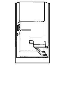
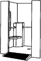
BathtubsThere are two basic types of showers for handicap use. Wide shower enclo­sures are one type, and square shower enclosures are the other. Shower stalls may be made on site or purchased as pre-fab units (Fig. 10.12). When a wide shower enclosure is used, it must have a minimum width of 60 inches. The depth must be no less than 30 inches. Thresholds are prohibited. Showers of this type must be made to allow wheelchairs to enter the enclosure. Shower valves must be mounted on the back wall. The minimum distance for the valve
Bathtubs

6950 RH Seat/6951 LH Seat Liberte

• Has fold-down seat. Placed at 18" height for easy transfer from wheelchair to seat.

• Two built-in soap shelves.

• One vertical and three horizontal grab bars.

• Inside diameter of 5′ for easy wheelchair turn inside stall

• Entry ramp 36" wide with gentle 8.3% grade.

• Lipped door ledge to prevent rolling out of stall.

• Anti-skid floor mat included.

• White.

• Optional dome (6951) available.


FIGURE 10.12 ■ Handicap shower with seat and ramp. (Courtesy of McGraw-Hill)

from the shower floor is 38 inches, with a maximum height of 48 inches. A grab bar must be mounted along the entire length of the three walls that form the enclosure. All grab bars are to be set at least 33 inches above the shower floor, but not more than 36 inches above the floor. And, the bars shall be mounted parallel to the shower floor.

Подпись: ► sensible shortcutBathtubsA shower enclosure that is square in design has to be at least 36 inches square.

Seats for this type of shower may have a seat with a maximum width of 16 inches.

Подпись: Don’t order handicap fixtures until you are sure that they are approved for use in your jurisdiction. When in doubt, check with your local code officer to confirm approval for specific fixtures.The seat must be mounted along the en­tire length of the shower. Seat height is established as a minimum of 17 inches above the shower floor, with a maximum height of 19 inches. Grab bars must be in­stalled to extend from the edge of the seat around the sidewall opposite the seat. These bars must be at least 33 inches above the shower floor, and not more than 36 inches above the floor. A shower valve must be mounted on the sidewall opposite the seat. The minimum height
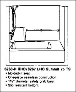
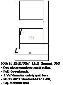
of the shower valve shall be 38 inches above the floor. A maximum height of 48 inches is allowed for the installation of a shower valve.

BATHING UNITS

Bathing units for handicap use are required to be equipped with grab bars.

Bathtubs and showers for handicap use are often different in size and equip­ment from what you would find in a standard fixture (Fig. 10.10, Fig. 10.11).

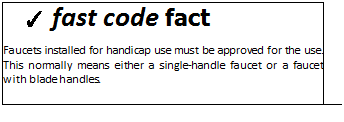
The minimum clear space in front of a bathing unit is 30 inches from the edge of the enclosure away from the unit and 48 inches wide. If a situation exists where a bathing unit is not accessible from the side, the clear space in front of the unit must be increased to a minimum of 48 inches. Faucets for showers and bathtubs must be equipped with a hand-held shower. The hose for these showers must be a minimum of 60 inches in length. The faucets must be able to be opened and closed with a maximum force of five pounds.

Grab bars are required in handicap bathing units. Diameters and widths of grab bars must be a minimum of 1.25 inches and a maximum of 1.5 inches. The bars must be spaced 1.5 inches from the wall. It is not al­lowable for the bars to rotate. All bars used must be approved for the in­tended use.

BATHING UNITS

FIGURE 10.10 ■ Handicap bathtub. (Courtesy of McGraw-Hill)

BATHING UNITS

FIGURE 10.11 ■ Handicap shower.

(Courtesy of McGraw-Hill)

KITCHEN SINKS

Kitchen sinks require a minimum clear space in front of them that must be 30 inches by 30 inches. This is based on a measurement made from the front face of the kitchen sink, counter, or vanity. Measuring from the finished floor to the top edge of a kitchen sink or counter should result in a measurement of 34 inches, maximum. Unobstructed knee clearance with a minimum of 29 inches high by 8 inches deep should be provided. Toe clearance should be a mini­mum of 9 inches high by 9 inches deep, provided from the sink to the wall.

Additional requirements for a handicap kitchen sink require that all ex­posed hot-water piping be insulated. Faucets should be installed so that they are no more than 25 inches from the front face of the lavatory, counter, or vanity. And, the faucet must be able to be turned on and off with a maximum force of five pounds.

LAVATORIES

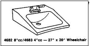
Lavatories installed for handicap use must be of a type that is accessible by a person in a wheelchair (Fig. 10.9). The minimum clear space in front of a lava­tory must be 30 inches by 30 inches. This is based on a measurement made from the front face of the lavatory, counter, or vanity. Measuring from the fin­ished floor to the top edge of a lavatory or counter should result in a meas­urement of 35 inches. How much clearance is required under the lavatory? Unobstructed knee clearance with a minimum of 29 inches high by 8 inches deep should be provided. Toe clearance should be a minimum of 9 inches high by 9 inches deep, provided from the lavatory to the wall.

Additional requirements for a handicap lavatory require that all exposed hot-water piping be insulated. Faucets should be installed so that they are no more than 25 inches from the front face of the lavatory, counter, or vanity. And, the faucet must be able to be turned on and off with a maximum force of five pounds. Now, what happens if the lavatory is installed in a privacy

Подпись:

LAVATORIES

compartment of a toilet? When a lava­tory is installed in a compartment, the lavatory must be located against the back wall, adjacent to the water closet. The edge of the lavatory must have a minimum of 18 inches of clear space, measured from the center of the toilet.

FACILITIES FOR HANDICAP TOILETS

Let’s talk about the facilities for handicap toilets (Fig. 10.8). When a handi­cap toilet is installed in a privacy compartment, the minimum net clear open­ing for the compartment must be at least 32 inches wide. The door of the
compartment must swing out, away from the toilet. The width of such a com­partment should be 36 inches, with a depth of 60 inches. Unlike a standard toilet where the side clearance is 15 inches, handicap toilets require a side dis­tance of 18 inches.

Подпись:

FACILITIES FOR HANDICAP TOILETS

Grab bars must be installed at a height of no less than 33 inches and no more than 36 inches above the finished floor. The bars must have a minimum length of 42 inches. They must be mounted on both sides of the compart­ment. When the bars are mounted, they must be mounted a maximum of 12 inches from the rear wall and extend a minimum of 54 inches from the rear wall. A rear grab bar, of at least 36 inches in length, must also be installed. This grab bar must be no more than 6 inches from the closest side­wall and extend a minimum of 24 inches beyond the centerline of the toilet away from the closest sidewall.

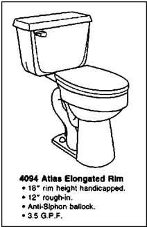
Toilets approved for handicap installations must be higher than a normal toilet. Most of them are 18 inches tall, but the allowable range is anything be­tween 16 and 20 inches above the finished floor. Rules for single-occupant arrangements vary a little from commercial installations. As always, check your local plumbing code for exact regulations in your region.