The remaining tables are different in content, but the procedures for using them are the same. Once you know the number of bedrooms and bathrooms for a dwelling, you can quickly and easily determine the minimum requirements for a water heater. You have just seen how simple the tables are. When you have a water heater to size, just refer to the tables in this chapter (Fig. 7.4, to 7.10) or the tables in your local codebook.
|
Number of bedrooms
|
2
|
3
|
4
|
5
|
|
Storage capacity (gallons)
|
30
|
40
|
40
|
50
|
|
Input in Btuh
|
36,000
|
36,000
|
38,000
|
47,000
|
|
Draw (gallons per hour)
|
60
|
70
|
72
|
90
|
|
Recovery (gallons per hour)
|
30
|
30
|
32
|
59
|
FIGURE 7.4 ■ Water heating sizing table for gas heaters (minimum recommendations). Assume 2 to 21/2 bathrooms.
|
Number of bedrooms
|
2
|
3
|
4
|
5
|
|
Storage capacity (gallons)
|
40
|
50
|
50
|
66
|
|
Input in Btuh
|
4.5 KW
|
5.5 KW
|
5.5 KW
|
5.5 KW
|
|
Draw (gallons per hour)
|
58
|
70
|
72
|
88
|
|
Recovery (gallons per hour)
|
18
|
22
|
22
|
22
|
FIGURE 7.5 ■ Water heating sizing table for electric heaters (minimum recommendations). Assume 2 to 21/2 bathrooms.
|
Number of bedrooms
|
2
|
3
|
4
|
5
|
|
Storage capacity (gallons)
|
30
|
30
|
30
|
30
|
|
Input in Btuh
|
70,000
|
70,000
|
70,000
|
70,000
|
|
Draw (gallons per hour)
|
89
|
89
|
89
|
89
|
|
Recovery (gallons per hour)
|
59
|
59
|
59
|
59
|
FIGURE 7.6 ■ Water heating sizing table for oil-fired heaters (minimum recommendations). Assume 2 to 21/2 bathrooms.
|
Number of bedrooms
|
3
|
4
|
5
|
6
|
|
Storage capacity (gallons)
|
40
|
50
|
50
|
50
|
|
Input in Btuh
|
38,000
|
38,000
|
47,000
|
50,000
|
|
Draw (gallons per hour)
|
72
|
82
|
90
|
92
|
|
Recovery (gallons per hour)
|
32
|
32
|
40
|
42
|
FIGURE 7.7 ■ Water heating sizing table for gas heaters (minimum recommendations). Assume 3 to 31/2 bathrooms.
|
Number of bedrooms
|
3
|
4
|
5
|
6
|
|
Storage capacity (gallons)
|
50
|
66
|
66
|
80
|
|
Input in Btuh
|
5.5 KW
|
5.5 KW
|
5.5 KW
|
5.5 KW
|
|
Draw (gallons per hour)
|
72
|
88
|
88
|
102
|
|
Recovery (gallons per hour)
|
22
|
22
|
22
|
22
|
FIGURE 7.8 ■ Water heating sizing table for electric heaters (minimum recommendations). Assume 3 to 3V2 bathrooms.
|
Number of bedrooms
|
3
|
4
|
5
|
6
|
|
Storage capacity (gallons)
|
59
|
59
|
59
|
59
|
|
Input in Btuh
|
70,000
|
70,000
|
70,000
|
70,000
|
|
Draw (gallons per hour)
|
89
|
89
|
89
|
99
|
|
Recovery (gallons per hour)
|
59
|
59
|
59
|
59
|
FIGURE 7.9 ■ Water heating sizing table for oil-fired heaters (minimum recommendations). Assume 3 to 3V2 bathrooms.
 |
|
Column 1
|
Column 2
|
|
Buildings of ordinary tightness
|
Buildings of unusually tight construction
|
|
Condition
|
Size of opening or duct
|
Condition
|
Size of opening or duct
|
|
Appliance in unconfined2
space
|
May rely on infiltration alone.
|
Appliance in unconfined2 space:
Obtain combustion air from outdoors or from space freely communicating with outdoors.
|
Provide two openings, each having 1 sq. in. per 5,000 Btu/h input.
|
|
Appliance in confined4 space
1. All air from inside building
|
Provide two openings into enclosure each having one square inch per 1,000 Btu/h input freely communicating with other unconfined interior spaces. Minimum 100 sq. in. each opening.
|
Appliance in confined4 space:
Obtain combustion air from outdoors or from space freely communicating with outdoors.
|
1. Provide two vertical ducts or plenums: 1 sq. in. per 4,000 Btu/h input each duct or plenum.
2. Provide two horizontal ducts or plenums: 1 sq. in. per 2,000 Btu/h input each duct or plenum.
3. Provide two openings in an exterior wall of the enclosure: each opening 1 sq. in per 4,000 Btu/h input.
4. Provide one ceiling opening to ventilated attic and one vertical duct to attic: each opening 1 sq. in. per 4,000 Btu/h input.
|
|
2. Part of air from inside building
|
Provide two openings into enclosure3 from other freely communicating unconfined2 interior spaces, each having an area of 100 sq. in. plus one duct or plenum opening to outdoors having an area of 1 sq. in. per 5,000 Btu/h input rating.
|
|
|
3. All air from outdoors: Obtain from outdoors or from space freely communicating with outdoors.
|
Use of any of the methods listed for confined space in unusually tight construction as indicated in Column 2.
|
|
5. Provide one opening in enclosure ceiling to ventilated attic and one opening in enclosure floor to ventilated crawl space: each opening 1 sq. in. per 4,000 Btu/h input.
|
’For location of opening, see Section 1307(c).
2As defined in Section 122,
3When the total input rating of appliances in enclosure exceeds 100,000 Btu/h, the area of each opening into the enclosure shall be increased 1 sq. in. for each 1,000 Btu/h over 100,000,
4As defined in Section 104(h).
|
|
FIGURE 7.10 ■ Size of combustion air openings or ducts for gas-or liquid-burning water heaters. [Courtesy of Uniform Plumbing Code)
ome plumbers work their entire careers without ever having to know anything about water pumps. Other plumbers deal with pumps on a frequent basis. The difference is where the plumbers work. I’ve never worked in New York City, but I suppose there are not many water pumps to be installed or serviced. But where I live, in Maine, there are more homes served by private water wells than you can shake a stick at. When I lived in Virginia, there were plenty of water pumps, too. Some of the pumps are jet pumps and others are submersible pumps. The two are very different, even though they do the same job.
Jet pumps are at their best when used in conjunction with shallow wells, with depths of say 25 feet or less. Two-pipe jet pumps can be used with deep wells, but a submersible pump is usually a better option for deep wells. Sizing water pumps and pressure tanks is routine for some plumbers and foreign to others. This chapter is going to give you plenty of data to use when working with pump systems.
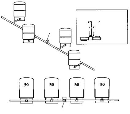
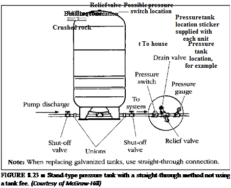
The illustrations I have to offer you in this chapter are detailed and selfexplanatory. I believe that you will be able to use this chapter as a quick-reference guide to most of your pump questions. Look over the following illustrations and you will find data on jet pumps, submersible pumps, and pressure tanks. The data will prove very helpful if you become involved with the installation, sizing, or repair of water pumps (Figs. 8.1 to 8.37).
135
|
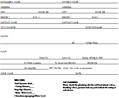
This check list is intended to bdp in making reliable submersible pump installations. Other data for specific pumps may be needed.
|
|
|
1. Motor Inspection
___ Л. Verify thai lire model. HP or KW. voltage, phase
and heitz on the motor nameplate match the installation requirements. Consider any special comision resistance required.
___ B, Check that I he motor lead assembly ts tight in Uie
motor and that the motor and lead are not damaged.
___ C. Test insulation resistance using a 500 or l(MX) volt
DC inegohmmeier, from each lead wire to the motor frame, Resistance should be at least 20 megohms, motor only, no cable.
D. Keep a record of motor model number, HP or KW, voltage, date code and serial number,
2. Pump Inspection
___ A. Check that the pump rating matches the motor, and
that it is not damaged.
___ B. Verily that the pump shaft turns freely.
3. Pump/Motor Assembly
___ A. If not yet assembled, check that pump and motor
mounting faces are free from dirt and uneven paint
thickness.
___ B, Assemble the pump and motor together so their
mourning faces are in contact, then tighten assembly holis or nuts evenly to manufacturer specifications.
И it is visible, chuck dial the pump shaft is raised slightly by assembly to the motor, conlilining impeller running clearance.
___ C. If accessible, check that the pump shaft rums freely.
___ D. Assemble the pump lead guard over the motor
leads. Do not eui nr pinch lead wire during assembly or handling of the pump during installation.
4. Power Supply and Controls
__ A. Verify that the power supply voltage, here?., and
KVA capacity malch motor requirements.
B, Use a matching control box with each single phase three wire motor.
___ C. Check that the electrical installation arid controls
meet all safety regulations and match the motor requirements, including fuse or circuit breaker size and motor overload protection. Connect all metal plumbing and electrical enclosures to (he power supply ground in prevent shock hazard, Comply with National and local codes.
5. Lightning and Surge Protection
___ A. Use properly rated surge (lightning) arresiors on all
submersible pump installations unless the installation is operated directly from an individual generator and/or is not exposed to surges. Motors 5HP and smaller which are marked “Equipped with Lightning Arrestors’contain internal arrestors.
|
|
|
B. Ciround all above ground arrestors with copper wire directly to the motor frame. or to metal drop pipe or casing which reaches below the well pumping level, Connecting to a ground rod does not provide good surge protection.
|
|
|
6. Electrical Cable
___ A. Use cable suitable for use in water, sized to carry’ the
motor current without overheating in water and in air, and complying with local regulations. To maintain adequate voltage at die motor, use lengths no longer than specified in die motor manufacturer s cable charts,
___ B. Include a ground wire to liie pump if required by
codes or. surge protection, connected lo the power supply ground Always ground any pump operated outside a drilled well.
7. Well Conditions
___ A, For adequate cooling, motors must have at least the
water flow shown on ils nameplate. If well conditions and construction do not assure this much water How will always come from below the motor, use a flow’ sleeve as shown in the Application, Installation & Maintenance Manual
___ B. If water temperature exceeds JO degrees C <86 T).
reduce live motor loading or increase the How rate to prevent overheating, as specified in the Application. Installation & Maintenance Manual.
B. Pump/Motor Installation
___ A. Splice motor leads lo supply cable using electrical
grade solder or compression connectors, and carefully insulate each splice with watertight tape or adhesive-lined shrink tubing, as shown in motor or pump installation data.
___ B. Support the cable to the delivery pipe every 10 feel
(3 meters) with straps or tape strong enough to prevent sagging. Use pads between cable and any metal straps.
___ C. A check valve in the delivery pipe is recommended,
even though a pump may be reliable without one. More than one check valve may be required, depending cm valve rating and pump setting. Install the lowest check valve below the lowest pumping level of the well, lo avoid hydraulic shocks which may damage pipes, valve or motor.
___ D. Assemble all pipe joints as lightly as practical, to
prevent unscrewing from motor torque. Recommended torque is at least 10 pound feet per HP (2 mcter-KG per KWi.
___ E. Set the pump fur enough below the lowest pumping
level to аччигс the pump inlet will always have at least the Net Positive Suction 1 lead |NPSI l) specified by the pump manufacturer, but at least 11) leet (3 meters) from the bottom of the well lo allow for sediment build up.
|
|
|
___ F. Cheek, insulation resistance from dry motor cable
ends to ground as the pump is installed, using а 5Ш or KM) volt DC megohm meter. Resistance may drop gradually as mere cable enters the water, but any sudden drop indicates possible cable, splice or motor lead damage. Resistance should meet motor manufacturer data,
9. After Installation
___ A. Check all electrical and waterline connections and
parts before starting the pump, Make sure water delivery will not wd any electrical parts, and recheck that overload protection in three phase controls meets requirements.
___ B. Strut the pump and check motor amps and pump
delivery. If normal, continue to run the pump until delivery is clear. If three phase pump delivery is low, it may be running backward because phase, sequence is reversed. Rotation may be reversed (with power off) by interchanging any two motor lead connections to the power supply.
___ C. Connect three phase motors for current balance
within 5% of average, using motor manufacturer instructions. Unbalance over 5c7c will cause higher motor temperatures and may cause overload trip, vibration, and reduced life.
___ D. Make sure that starling, running and stopping cause
no significant vibration or hydraulic shocks.
___ E. A Iter at least 15 minutes running, verify that pump
output, electrical input, pumping level, and other characteristics arc stable and as specified.
Date____________________ Filled In By
10. Installation Data
Well Identification_________________________________ _________________________________________
Check By ____________________________________ _
Date___ /____ (_____
Notes __________________________________________
|
|
|
|
 |
 |
|
Pump Inlet Setting___
Flow Sleeve: No
|
|
|
|
|
Casing Depth______ Jt
□ Well Screen □ Perforated Casing From__ to_________ ft. &__ to________ ft-
|
|
|
– Well Depth_
Form No. 2207 2AM
|
|
|
Average water requirements for general
|
|
|
service around the home and farm
|
|
|
Each person per day, for all purposes
|
|
75 gal.
|
|
Each horse, dry cow, or beef animal
|
|
12 gal.
|
|
Each milking cow
|
|
35 gal.
|
|
Each hog per day
|
|
4 gal.
|
|
Each sheep per day
|
|
2 gal.
|
|
Each 100 chickens per day
|
|
4 gal.
|
|
Average amount of water required by
|
|
|
various home and yard fixtures
|
|
|
Drinking fountain, continuously flowing
|
50 to 100 gal. per day
|
|
Each shower bath
|
Up to 30 gal. @ 3-5 gpm
|
|
To fill bathtub
|
|
30 gal.
|
|
To flush toilet
|
|
6 gal.
|
|
To fill lavatory
|
|
2 gal.
|
|
To sprinkle V4" of water on each 1000
|
|
|
|
square feet of lawn
|
|
1б0 gal.
|
|
Dishwashing machine — per load
|
7 gal. @ 4 gpm
|
|
Automatic washer —per load
|
Up to 50 gal. @ 4-6 gpm
|
|
Regeneration of domestic water softener
|
|
50-100 gal.
|
|
Average flow rate requirements by
|
|
|
various fixtures
|
|
|
|
(gpm = gal. per minute; gph =
|
gal. per hour)
|
|
|
Shower
|
|
3-5 gpm
|
|
Bathtub
|
|
3-5 gpm
|
|
Toilet
|
|
3 gpm
|
|
Lavatory
|
|
3 gpm
|
|
Kitchen sink
|
|
2-3 gpm
|
|
У2” hose and nozzle
|
|
200 gph
|
|
1/4" hose and nozzle
|
|
300 gph
|
|
Lawn sprinkler
|
|
120 gph
|
FIGURE 8.3 ■ Average water requirements for general service. (Courtesy of McGraw-Hill)
|
Each horse
|
Approx. Gallons Per Day
12
|
|
Each producing cow
|
15
|
|
Each nonproducing cow
|
12
|
|
Each producing cow with drinking cups
|
30-40
|
|
Each nonproducing cow with drinking cups
|
20
|
|
Each hog
|
4
|
|
Each sheep
|
2
|
|
Each 100 chickens
|
4-10
|
|
Yard fixtures:
|
|
Vi-inch hose with nozzle
|
200
|
|
M-inch hose with nozzle
|
300
|
|
Bath houses
|
10
|
|
Camp
|
|
Construction, semipermanent
|
50
|
|
Day (with no meals served)
|
15
|
|
Luxury
|
100-150
|
|
Resorts (day and night, with limited plumbing)
|
50
|
|
Tourists with central bath and toilet facilities
|
35
|
|
Cottages with seasonal occupancy
|
50
|
|
Courts, tourists with individual bath units
|
50
|
|
Clubs
|
|
Country (per resident member)
|
100
|
|
Country (per nonresident member present)
|
25
|
FIGURE 8.4 ■ Daily water requirements. (Courtesy of McGraw-Hill)
|
Dwellings
Luxury
Multiple family, apartments (per resident)
Rooming houses (per resident)
Single family Estates _
Factories (gallons/person/shift)
Institutions other than hospitals Hospitals (per bed)
Laundries, self-serviced (gallons per washing, i. e., per customer)
Motels
With bath and toilet (per bed space)
Parks
Overnight with flush toilets Trailers with individual bath units Picnic
With bath houses, showers, and flush toilets With only toilet facilities (gal./picnicker) Restaurants with toilet facilities (per patron)
Without toilet facilities (per patron)
With bars and cocktail lounge (additional quantity) Schools Boarding
Day with cafeteria, gymnasiums and showers Day with cafeteria but no gymnasiums or showers Service stations (per vehicle)
Stores (per toilet room)
Swimming pools Theaters
Drive-in (per car space)
Movie (per auditorium seat)
Workers
Construction (semipermanent)
Day (school or offices per shift)
|
|
|
75
60
50
75
100-150
15-35
75-125
250-400
50
100
25
50
20
10
10
3
2
50-70
25
20
10
400
10
5
5
50
15
|
|
|
Providing an adequate water supply provides for a healthy family and higher production from livestock. Assuming the total daily requirement is calculated to be 1200 gpd (gallons per day), a pump would be selected for a capacity of 10 gpm (gallons per minute) based on the following formula:
|
|
|
1200 gph t 2 equals 600 gph (gal. per hr.)
|
|
 |
|
FIGURE 8.4 ■ (Continued) Daily water requirements. (Courtesy of McGraw-Hill)
|
|

|
Engineering Data
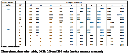
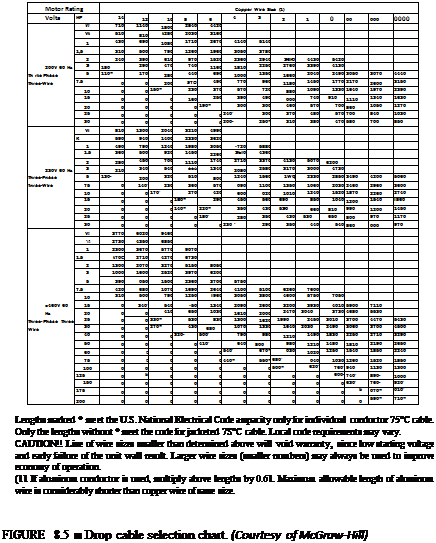
Drop Cable Selection Chart
Single-phase, two or three-wire cable, 60 Hz (service entrance to motor)
|
|
 |
 |

|
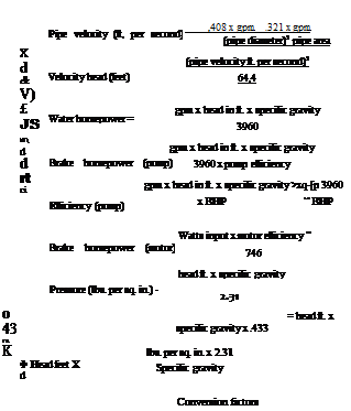
Engineering data
Formulas and conversion factors
Centrifugal pumps
|
|
 |
|
|
|
Volume
1 U. S, gallon – 231 cu. in,
1 U. S. gallon =■ 3-785 liters 1 Imperial gallon *1.2 U. S.
gallons
1 barrel (oil) я 42 U. S, gallons 1 cubic foot * 7.48 U. S, gallons
1 acre foot = 325,850 U. S.
gallons
1 cubic meter * 264,2 U. S.
gallons
Weight
1 U. S. gallon water weighs 8,35 lbs.
1 cubic foot water weighs
|
|
|
Head
1 lb. per sq. in. = 2.31 ft. of water 1 foot of water = 0-433 lbs. per sq. in. 1 inch of mercury = 1,133 ft. of water 1 atmosphere (sea level) – 14.7 lbs, per sq. in.
1 kilogram per sq. centimeter * 14,22 lbs. per sq. in.
Length
1 meter » 3.28 feet – 39.37 inches Power
1 horsepower = 745-7 watts 1 kilowatt * 1000 watts 1 kilowatt = 1.341 HP 100 boiler HP requires 7 gpm feed water approximately.
|
|
|
|


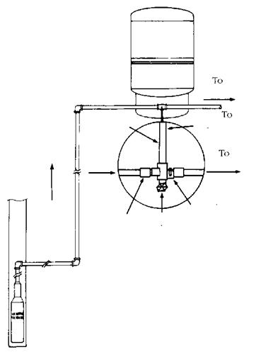

FIGURE 8.7 ■ Pressure tank in use with a submersible pump. (Courtesy of McGraw-Hill)
|
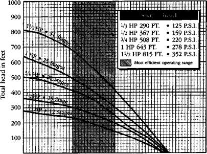
О 1 2 3 456789 10 11 12
U. S. gallons per minute
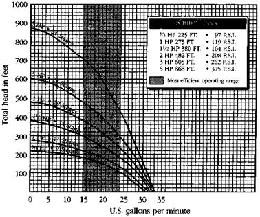
FIGURE 8.8 ■ Performance rating chart for pump with 5 gallon-per- minute output. (Courtesy of McGraw-Hill)
|
|
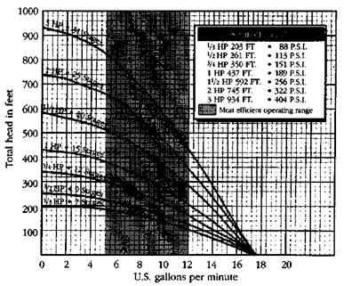
FIGURE 8.9 ■ Performance rating chart for pump with 10 gallon-per- minute output. (Courtesy of McGraw-Hill)
|
|
|
 |
|
|
|
|
|
|
|
|
|
|
|
|
|
FIGURE 8.10 ■ Performance rating chart for pump with 13 gallon-per – minute output. (Courtesy of McGraw-Hill)
|
|
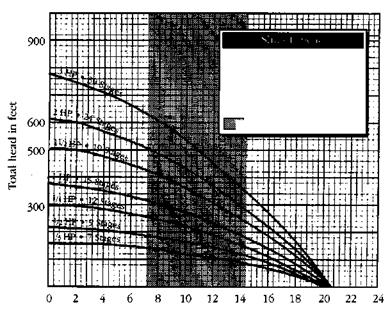

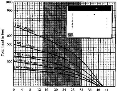

FIGURE 8.12 ■ Performance rating chart for pump with 25 gallon-per – minute output. (Courtesy of McGraw-Hill)
|
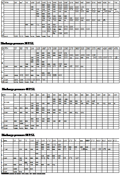
Output In gallons per hour
Discharge pressure 0 P. S.I.
|
|
 |
|
|
|
Impeller
|
Pres, switch
|
Suction
|
Discharge
|
Shipping
|
|
Model no.
|
HP
|
Volts
|
material
|
setting
|
pipe size
|
size
|
weight
|
|
8130
|
Уз
|
115
|
Plastic
|
20-40
|
1У4”
|
■1/4"
|
46 lbs.
|
|
8131
|
Уз
|
115
|
Brass
|
20-40
|
1У4"
|
|
48 lbs.
|
|
8150
|
y2
|
115/230
|
Plastic
|
20-40
|
1У4”
|
‘■’A"
|
48 lbs.
|
|
8151
|
y2
|
115/230
|
Brass
|
20-40
|
1У4"
|
|
50 lbs.
|
|
8170
|
3/4
|
115/230
|
Plastic
|
30-50
|
IV*’
|
%"
|
50 lbs.
|
|
8171
|
3/4
|
115/230
|
Brass
|
30-50
|
1У4"
|
%"
|
52 lbs.
|
|
8110
|
1
|
115/230
|
Plastic
|
30-50
|
1У4”
|
|
52 lbs.
|
|
8111
|
1
|
115/230
|
Brass
|
30-50
|
1У4"
|
|
53 lbs.
|
FIGURE 8.14 ■ Performance ratings for jet pumps. (Courtesy of McGraw-Hill)
FIGURE 8.15 ■ Performance ratings for multi-stage pumps. [Courtesy of McGraw-Hill)
|
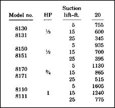
FIGURE 8.16 ■ Shallow-well performance chart. (Courtesy of McGraw-Hill)
|
|
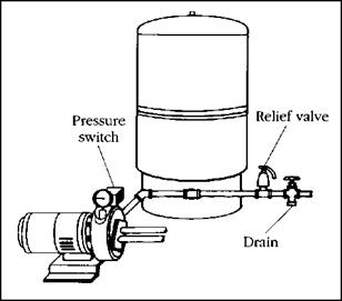
FIGURE 8.17 ■ A typical jet-pump set-up. (Courtesy of McGraw-Hill)
|
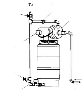

FIGURE 8.18 ■ A jet pump mounted on a pressure tank with a pump bracket. (Courtesy of McGraw-Hill)
|
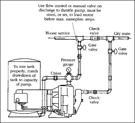
FIGURE 8.19 ■ A typical piping arrangement for a jet pump. (Courtesy of McGraw-Hill)
|
|
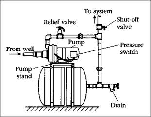
FIGURE 8.20 ■ Bracket-mounted jet pump on a horizontal pressure tank. (Courtesy of McGraw-Hill)
|
|
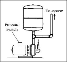
FIGURE 8.21 ■ Small, vertical pressure tank installed above pump. (Courtesy of McGraw-Hill)
|
|
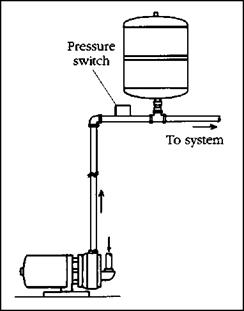
FIGURE 8.22 ■ Small, vertical pressure tank installed above pump. (Courtesy of McGraw-Hill)
|
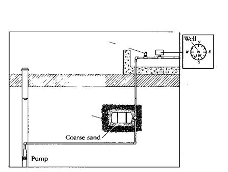 FIGURE 8.24 ■ An underground installation of a pressure tank. (Courtesy of McGraw-Hill)

|

FIGURE 8.25 ■ In-line pressure tank. (Courtesy of McGraw-Hill)
|
|
|
|
 |
|
|

|
Model
|
Dimensions
|
Total
|
1,5/3,0 bar
|
2,0/3,5 bar
|
2,5/4,0 bar
|
System
|
Precharge
|
Shipping
|
|
No.
|
Diameter
|
Height
|
Volume
|
|
Drawdown
|
|
Connection
|
Pressure
|
Wt./Vol.
|
|
mm
|
mm
|
Ltr
|
Liter
|
Liter
|
Liter
|
FT
|
bar
|
KG/m3
|
|
WX 2,6
|
156
|
228
|
2.6
|
1,0
|
0,9
|
0,8
|
3/4
|
1,5
|
1,0/,005
|
|
WX4
|
156
|
302
|
4,1
|
1,5
|
1,4
|
1,2
|
3/4
|
1.5
|
1,5/,007
|
|
WX8
|
200
|
320
|
8
|
3,0
|
2.6
|
2,4
|
3/4
|
1,5
|
2,3/,02
|
|
WX 18
|
280
|
380
|
18
|
6,7
|
6,0
|
5,4
|
3/4
|
1,5.
|
4,1 / ,03
|
|
WX33
|
280
|
630
|
33
|
12,4
|
10,9
|
9,9
|
3/4
|
1,5
|
6,8 / ,05
|
|
|

FIGURE 8.27 ■ Specifications for in-line pressure tanks. (Courtesy of McGraw-Hill)
|
1,5/3,0 bar
|
2,0/3,5 bar
|
2,5/4,0 bar
|
System
Connection
|
Precharge
Pressure
|
Shipping
Wt./Vol.
|
|
Liter
|
Drawdown
Liter
|
Liter
|
|
FT
|
bar
|
KG /m3
|
|
30
|
27
|
24
|
2
|
3,5
|
59 / ,25
|
|
68
|
60
|
54
|
2
|
3,5
|
83 / ,39
|
|
113
|
99
|
90
|
2
|
3,5
|
155/,53
|
|
225
|
198
|
180
|
2
|
3,5
|
285/1,06
|
|
300
|
264
|
240
|
2
|
3,5
|
360/1,32
|
|
375
|
330
|
300
|
3
|
3,5
|
400 /1,96
|
|
600
|
528
|
480
|
3
|
3,5
|
540/2,74
|
|
750
|
660
|
600
|
3
|
3,5
|
780 / 3,59
|
|
30
|
27
|
24
|
2
|
3,5
|
59/,25
|
|
68
|
60
|
54
|
2
|
3,5
|
83 / ,39
|
|
113
|
99
|
90
|
2
|
3.5
|
155/,53
|
|
225
|
198
|
180
|
2
|
3,5
|
285 /1,06
|
|
300
|
264
|
240
|
2
|
3,5
|
360 /1,32
|
|
375
|
330
|
300
|
3
|
3,5
|
400 /1,96
|
|
600
|
528
|
480
|
3
|
3.5
|
540/2,74
|
|
750
|
660
|
600
|
3
|
3,5
|
7890/3,59
|
|
30
|
27
|
24
|
2
|
3,5
|
64 / ,25
|
|
68
|
60
|
54
|
2
|
3,5
|
102/,39
|
|
113
|
99
|
90
|
2
|
3,5
|
220 / ,53
|
|
225
|
198
|
180
|
2
|
3,5
|
400/1,06
|
|
300
|
264
|
240
|
2
|
3,5
|
505/1,32
|
|
375
|
330
|
300
|
3
|
3,5
|
560 / 1,96
|
|
600
|
528
|
480
|
3
|
3,5
|
756/2,74
|
|
750
|
660
|
600
|
3
|
3,5
|
1330/3,5
|
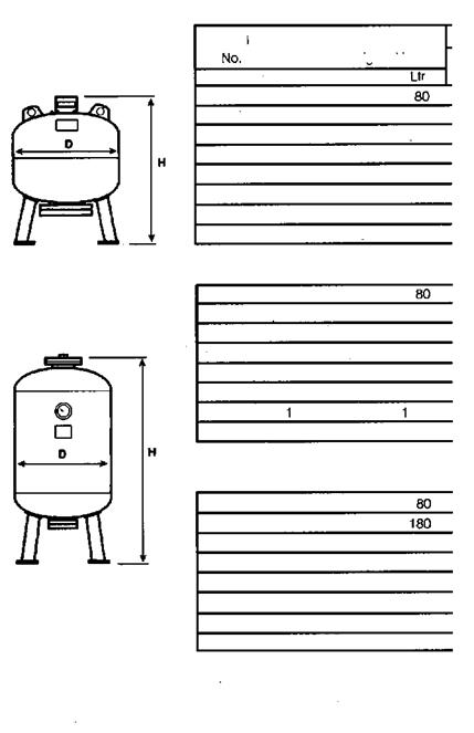
FIGURE 8.28 ■ (Continued) Specifications for pressure tanks with replaceable bladder designs. (Courtesy of McGraw-Hill)
|
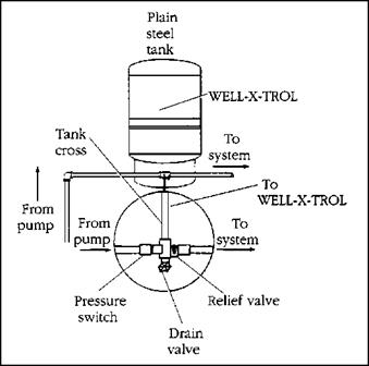
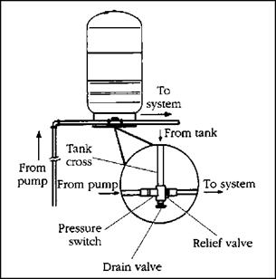
FIGURE 8.29 ■ Detail for a tank-tee set-up. (Courtesy of McGraw-Hill)
|
|
|
Dimensions
|
Total
|
Max.
|
Drawdown
|
|
ShipplRQ
|
|
Model
|
Diameter
|
Height
|
Volume
|
Accept.
|
2W40
|
30/50
|
40/50
|
m (Vo i. >
|
|
No.
|
(ini)
|
(in)
|
(tali)
|
Factor
|
(gala)
|
(gall)
|
(gala)
|
H>i feu 44>
|
|
WX-103-PS
|
12 V2
|
11 VA
|
8.6
|
028
|
3 1
|
2.7
|
22
|
20(2.4}
|
|
WX 200-PS
|
17 W
|
15 *8
|
140
|
0.31
|
5.2
|
43
|
38
|
29(4 0)
|
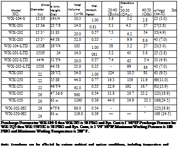
Precharge Pressure is 30 PSIG and Sys. Conn, is *4“ NPTM Filling lor 103-PS and i" NPTF Coupling lor 2Q0-PS. Maximum Working Pressure is 100 PSIG and Maximum Working Temperalure is 200" F.
|
|
|
|
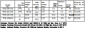 |


FIGURE 8.31 ■ Underground pressure tank specifications. (Courtesy of McGraw-Hill)

|
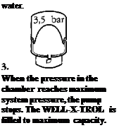
When the pump starts, water enters the WELL-X-TROL as system pressure passes the minimum pressure precharge. Only usable water is stored.
|
|
|
WELL-X-TROL has a sealed-in air chamber that is pre-pfessurized before it leaves our factory. Air and water do not mix eliminating any chance of “waterlogging” through loss of air to system
|
|
 |
|
When water is demanded, pressure in the air chamber forces water into the system. Since WELL-X-TROL does not waterlog and consistently delivers the maximum usable water, minimum pump starts are assured.
|
|
|
|
|
Maximum starts per 24 hr. day
|
Motor rating
|
Single phase
|
Three phase
|
|
Up to 3A hp
|
300
|
300
|
|
1 hp thru 5 hp
|
100
|
300
|
|
7 У2 hp thru 30 hp
|
50
|
100
|
|
40 hp and over
|
|
100
|
|
|
|
|

|
|
 |
|
Operating pressure—psig
discharge 20/40 30/50 40/60
|
rate gpm (approx.) 2.5
|
ESP I
|
ESP II
|
ESP I
|
ESP II
|
ESP I
|
ESP II
|
|
WX-104
|
WX-201
|
WX-104
|
WX-202
|
WX-104
|
WX-202
|
|
5
|
WX-201
|
WX-205
|
WX-202
|
WX-205
|
WX-202
|
WX-250
|
|
7
|
WX-202
|
WX-250
|
WX-203
|
WX-251
|
WX-205
|
WX-251
|
|
10
|
WX-203
|
WX-251
|
WX-205
|
WX-302
|
WX-250
|
WX-302
|
|
12
|
WX-205
|
WX-302
|
WX-250
|
WX-302
|
WX-251
|
WX-350
|
|
15
|
WX-250
|
WX-302
|
WX-251
|
WX-350
|
WX-251
|
WX-350
|
|
20
|
WX-251
|
WX-350
|
WX-302
|
(2JWX-251
|
WX-302
|
(2)WX-302
|
|
25
|
WX-302
|
(2JWX-302
|
WX-302
|
(2)WX-302
|
WX-350
|
(3)WX-251
|
|
30
|
WX-302
|
(2)WX-302
|
WX-350
|
(DWX-302
|
WX-350
|
(2)WX-350
|
|
35
|
WX-350
|
(DWX-302
|
WX-350
|
(DWX-350
(2)WX-350
|
(2JWX-251
|
(3)WS-302
|
|
40
|
WX-350
|
(DWX-350
(2)WX-350
|
(2)WX-251
|
(3)WX-302
|
(2)WX-302
|
(DWX-302
|
|
|
|
|
|
|
(2)WX-350
|
|
|
FIGURE 8.34 ■ Sizing and selection information for perssure tanks. (Courtesy of McGraw-Hill)
Posted by admin on 17/ 11/ 15
We will start our sizing exercises with homes where less than two bathrooms are present. You will see tables for gas-fired, electric, and oil-fired water heaters. The number of bedrooms in our sample homes can range from one to three. You will have to use the chart to size a water heater for the examples given. Let’s start with a gas-fired water heater. The house we will size it for will have two bedrooms and one bathroom. What size water heater is needed (Fig. 7.1)?
All you have to do is scan the table for the answer to sizing question. Look under the heading for two bedrooms and run down to the column that lists storage. You will see that a 30-gallon water heater is the minimum size recommended for the application. You will also note that the water heater will recover fully in one hour. Personally, i’d probably up the size of the
|
Number of bedrooms
|
1
|
2
|
3
|
|
Storage capacity (gallons)
|
20
|
30
|
30
|
|
Input in Btuh
|
27,000
|
36,000
|
36,000
|
|
Draw (gallons per hour)
|
43
|
60
|
60
|
|
Recovery (gallons per hour)
|
23
|
30
|
30
|
FIGURE 7.1 ■ Water heating sizing table for gas heaters (minimum recommendations). Assume less than two full bathrooms.
|
Number of bedrooms
|
1
|
2
|
3
|
|
Storage capacity (gallons)
|
20
|
30
|
30
|
|
Input in Btuh
|
2.5 KW
|
3.5 KW
|
4.5 KW
|
|
Draw (gallons per hour)
|
30
|
44
|
58
|
|
Recovery (gallons per hour)
|
10
|
14
|
18
|
FIGURE 7.2 ■ Water heating sizing table for electric heaters (minimum recommendations). Assume less than two full bathrooms.
|
Number of bedrooms
|
1
|
2
|
3
|
|
Storage capacity (gallons)
|
30
|
30
|
30
|
|
Input in Btuh
|
70,000
|
70,000
|
70,000
|
|
Draw (gallons per hour)
|
89
|
89
|
89
|
|
Recovery (gallons per hour)
|
59
|
59
|
59
|
FIGURE 7.3 ■ Water heating sizing table for oil-fired heaters (minimum recommendations). Assume less than two full bathrooms.
heater to 40 gallons, but by code in my region, a 30-gallon tank is all that would be required.
Now, suppose we had the same house but wanted to put an electric water heater in it? What size would we use? Refer to the table in Figure 7.2 to find your answer. In this case, the storage capacity for an electric heater is the same as that required of a gas-fired heater. A 30-gallon tank is all that is needed. But, look at the recovery rate for the electric heater. It’s about half as good as the recovery rate for a gas heater. This could be good reason to upgrade the heater to something larger or more powerful.
Let’s consider an oil-fired water heater. The basic table (Fig. 7.3) is the same, in terms of use. Again, using the same scenario, what size oil-fired heater would be needed? You will find that a 30-gallon tank is, once again, adequate. Check out the recovery rate. It’s great. As you can see, sizing water heaters with the tables provided here is truly easy.
Posted by admin on 17/ 11/ 15
izing water heaters is not a complicated process. It is, however, an important part of most plumbing jobs. Local code requirements call for minimum standards. The minimum facility requirements can be found in any major codebook or local code enforcement office. Since plumbing codes are regional, you will have to check your local code for exact requirements. But, the math that I’m about to show you will work in any location. Some of the numbers might be different, depending on code requirements, but the mathematical procedure will be the same.
When you figure the size of a water heater, remember that the codes offer suggestions and regulations for minimum requirements. The fact that a 40- gallon water heater will pass code may not mean that it is the best size heater for a given job. Use some common sense when sizing water heaters. Skimping on heater size can prove to be frustrating for your customers,- no one enjoys running out of hot water.
 There are three types of water heaters that we will discuss. Oil-fired water heaters are the least common of the three. Depending upon where you work, you might find that gas-fired water heaters or electric water heaters are the most prevalent in your region. Overall, electric water heaters are more prolific than gas-fired heaters. Regardless of which type of water heaters you will be working with, you will find the following sizing information helpful. There are three types of water heaters that we will discuss. Oil-fired water heaters are the least common of the three. Depending upon where you work, you might find that gas-fired water heaters or electric water heaters are the most prevalent in your region. Overall, electric water heaters are more prolific than gas-fired heaters. Regardless of which type of water heaters you will be working with, you will find the following sizing information helpful.
129
ELEMENTS OF SIZING
 Elements of sizing are something that you must understand, so let’s discuss what they are. The first element is the number of bathrooms in a home or building. When we move to the sizing charts in this chapter, you will see three different formats. This is due to the number of bathrooms. An additional element is the number of bedrooms found in a home. The number of bedrooms is very important. Of course, the storage size of a water heater is a key element. Other elements are the recovery rate, the draw, and the input in either British thermal units per hour (Btuh) or kilowatts (KW). i have prepared some sizing tables for you to use that will make your sizing efforts very easy. Let’s look at each table and do a few simple sizing examples to make sure you understand how to use the charts effectively. Elements of sizing are something that you must understand, so let’s discuss what they are. The first element is the number of bathrooms in a home or building. When we move to the sizing charts in this chapter, you will see three different formats. This is due to the number of bathrooms. An additional element is the number of bedrooms found in a home. The number of bedrooms is very important. Of course, the storage size of a water heater is a key element. Other elements are the recovery rate, the draw, and the input in either British thermal units per hour (Btuh) or kilowatts (KW). i have prepared some sizing tables for you to use that will make your sizing efforts very easy. Let’s look at each table and do a few simple sizing examples to make sure you understand how to use the charts effectively.
Posted by admin on 17/ 11/ 15
B101 Sizing Example
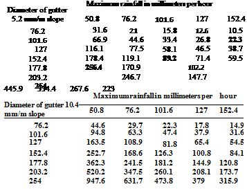
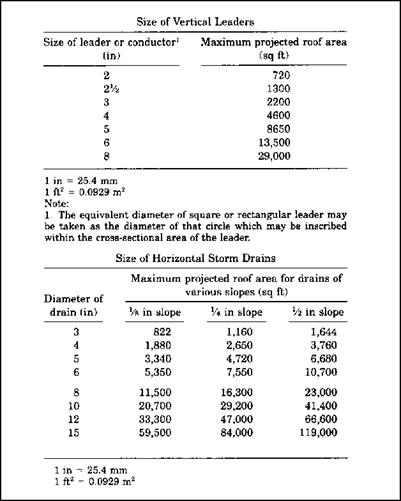
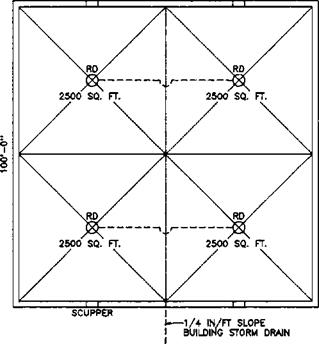
The following example gives one method of sizing the primary drain system and sizing the scuppers in the parapet walls. This method converts the roof area to an equivalent roof area for a 4-inch rate of rainfall so that Fig. 6.9 can be used as printed.
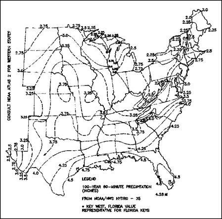
B101.1 Problem: Given the roof plan in Fig. 6.13 and the site location in Birmingham, Alabama, size the primary roof drain system and size the scuppers, denoting the required head of water above the scupper for the structural engineer.
Note: For the purposes of this appendix the following metric conversions are applicable:
1 in = 25.4 mm 1 ft = 305 mm 1 ft2 = 0.0929 m2
|
|
|
1001-O’
|
|
|
|
|
B101.2 Solution:
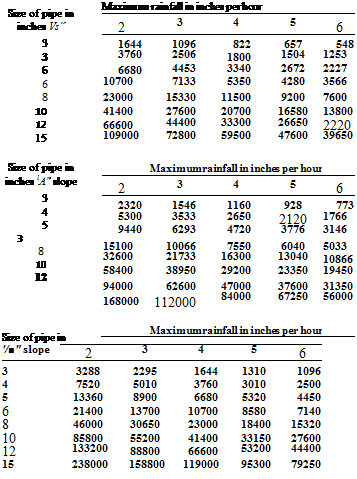
Step 1. From Fig. 6.11 the 100 year 60 minute precipitation is 3.75 inches per hour. Step 2. Each vertical drain must carry 2,500 sq ft of roof area at 3.75 inches per hour of rainfall. To convert to an area for a 4 inch per hour rainfall to enter Fig. 6.9 do this:
2.500 x 3.75 – e 4 — 2,344 sq ft. Enter Fig. 6.9 until you find a diameter pipe that will carry 2,344 sq ft. A minimum 4-inch vertical drain is required.
Step 3. Horizontal Drain 2,500 sq ft
To convert to an area for use in Fig. 6.9 do this:
2.500 X 3.75 H = 2,344 sq ft
Enter Fig. 6.9 until you find a diameter pipe that will carry 2,344 sq ft. A minimum 4-inch diameter pipe with a ‘A inch per foot slope will carry 2,650 sq ft. A minimum 4-inch diameter drain on a V* inch per foot slope is required.
Step 4. Horizontal Drain
5.0 sq ft
To convert to an area for use in Fig. 6.9 do this:
5.0 x 3.75 – e 4 = 4,688 sq ft.
Enter Table 1108.2 until you find a diameter pipe that will carry 4,688 sq ft. A 5-inch diameter pipe with a V* inch per foot slope will carry 4,720 sq ft. A minimum 5-inch diameter drain on a ‘A inch per foot slope is required.
Step 5. Horizontal Drain
10.0 sq ft
To convert to an area for use in Fig. 6.9 do this:
10.0 x 3.75 + 4 = 9,375 sq ft
Enter Fig. 6.9 until you find a diameter pipe that will carry 9,375 sq ft. An 8- inch diameter pipe on 1.4 inch per foot slope will carry 16,300 sq ft but a 6-inch will carry only 7,550 sq ft, therefore, use an 8-inch diameter drain on a V«inch per foot slope.
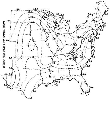
Step 6. From Fig. 6.12 the rate caused by a 100 year 15 minute precipitation is 7.2 inches per hour. The scuppers must be sized to carry the flow caused by a rain fall rate of 7.2 inches per hour.
Step 7. Each scupper is draining 2,500 sq ft of roof area. To convert this roof area to an area for use with Fig. 6.15 do this:
2.500 X 7.2 – E 4 = 4,500 sq ft
|
|
|
|
|
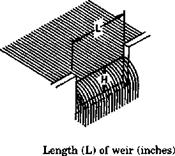
Enter Fig. 6.15 to find a length (see Fig. 6.15) and head that will carry 4,500 sq ft or more.
From Fig. 6.15 a 12-inch wide weir with a 4-inch head carries 6,460 sq ft.
Use 12-inch wide x 5-inch high scuppers at four locations.
A height of 5 inches is needed to assure an open area above the 4-inch head.
Step 8. Notify the structural engineer that the design of the roof structure must account for a height of water to the scupper entrance elevation plus 4 inches for the required head to cause design flow.
|
|
|
inches
|
4
|
6
|
8
|
12
|
16
|
20
|
24
|
|
1
|
273
|
418
|
562
|
851
|
1,139
|
1,427
|
1,715
|
|
2
|
734
|
1,141
|
1,549
|
2,365
|
3,180
|
3,996
|
4,813
|
|
3
|
1,274
|
2,023
|
2,772
|
4,270
|
5,768
|
7,267
|
8,766
|
|
4
|
1,845
|
2,999
|
4,152
|
6,460
|
8,766
|
11,073
|
13,381
|
|
6
|
2,966
|
5,087
|
7,204
|
11,442
|
15,680
|
19,918
|
24,160
|
Note:
Table based on rainfall of 4 inches per hour.
|
|
|
|
This page intentionally left blank.
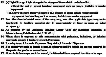
 There are a lot of restaurants in society. This is a common type of building for plumbers to work with. Finding the number of water closets and lavatories required in a restaurant is no more difficult than the other examples that we’ve been working with. However, there are additional requirements for restaurants.


 I want you to assume that there will be 62 people rated for the building that we are sizing. How many fixtures of each type will the building require? Take a moment to work the numbers, and then read the following results to see if you arrive at the same number that I do.
 alculating minimum plumbing facilities is a common part of a master plumber’s job. Knowing and understanding what is required in a building is not only a requirement for plumbers. Architects and engineers are often the people who determine the requirements for a new building. Local plumbing codes dictate minimum plumbing facilities. All plumbers have to do is understand the information provided for them in their codebooks. The information given by the codes is fairly simple, but gaining a complete understanding of it can be a bit intimidating. If the process is approached too lightly, misconceptions can cause mistakes. The people responsible for determining what plumbing will be included in a building cannot afford to make mistakes.
 It is common for plumbers to be provided with detailed blueprints when bidding jobs. The drawings will normally be submitted to a code enforcement office for approval. During this process, there are many ways for mistakes to be caught.
 If the person drawing the plans makes an error, the code officer who is working with the drawings is likely to find the problem. Plumbers bidding the job might catch the discrepancy.








 There are three types of water heaters that we will discuss. Oil-fired water heaters are the least common of the three. Depending upon where you work, you might find that gas-fired water heaters or electric water heaters are the most prevalent in your region. Overall, electric water heaters are more prolific than gas-fired heaters. Regardless of which type of water heaters you will be working with, you will find the following sizing information helpful.
 Elements of sizing are something that you must understand, so let’s discuss what they are. The first element is the number of bathrooms in a home or building. When we move to the sizing charts in this chapter, you will see three different formats. This is due to the number of bathrooms. An additional element is the number of bedrooms found in a home. The number of bedrooms is very important. Of course, the storage size of a water heater is a key element. Other elements are the recovery rate, the draw, and the input in either British thermal units per hour (Btuh) or kilowatts (KW). i have prepared some sizing tables for you to use that will make your sizing efforts very easy. Let’s look at each table and do a few simple sizing examples to make sure you understand how to use the charts effectively.

 Storm-water calculations stump some plumbers. I think that the problem for some plumbers is computing the amount of water accumulated due to structures on roofs. For example, if a roof has an enclosed stairway system, the walls and roof of the stairway have to be factored into the equation for what is required in rainfall drainage. Some plumbers find doing the math for roof drains, rain leaders, and other storm piping to be intimidating. Given the proper charts and tables, the job is not really too difficult.
 I used to teach code classes for plumbers who were preparing to take their licensing tests. After teaching the class for a while, I noticed some common elements from class to class. One common thread that seemed to run from class to class was a fear of doing storm-water calculations. I came to expect the classes to be intimidated by what I didn’t perceive to be any big deal. Knowing how to size a drainage system for storm water is a requirement for licensing where I live and work, so the people in the class had to address their fears. This, however, was true only of those going for their master’s license. Oddly enough, once they were given an example or two of how the work is done, most of them didn’t have any problem with their calculations.
