Cracking of SMA Course When Rolling

Cracking of the mixture under rollers may be observed when there is no bond between an SMA course and the layer under it or when the temperature of the SMA mixture is too high. The temperature of the mixture during compaction is easy to control, therefore it will not be a topic of this section.

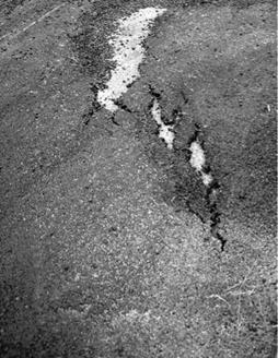
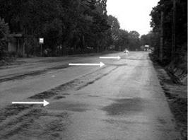
Figure 11.32 shows an old cement concrete pavement without a tack coat covered with a new SMA overlay. This resulted in a “dry slide” and the tearing of the SMA.

image141

FIGuRE 11.32 An example of the tearing of an SMA mat due to the lack of a tack coat on the cement concrete bottom layer. (Photo courtesy of Krzysztof BlaZejowski.)

A similar accident might happen while paving SMA on an old asphalt course with a very polished surface. By contrast, a course with too much tack coat may lead to a “wet slide” on a layer, also resulting in the tearing of the mat.

The conclusion to be drawn from these examples are self-evident—SMA paving should be preceded with proper tack coat. The amount of tack coat should be care­fully selected, taking into consideration the state of the underlying layer. Examples are shown in Chapter 10.

Roof Timber Framing for the Rest of Us

Подпись: Fig. 4.39: This was the post-and- beam frame for Log End Cottage. The ridge beam was a recycled eight-by-ten and already notched to receive the three-by-ten rafters, not shown. The roof slope is 8:12. Drawing by Marie Cyburt Taluba.image81Ridge beam. I cannot hide my love for a substantial ridge beam (also called, correctly but oddly, a ridgepole), and Гт not talking about the comparatively flimsy ridge “board” used by most stick-frame builders. No, I like something like the eight-by-ten at Log End Cottage (Fig. 4.39) or the ten-by-ten at Log End Cave (Fig. 4.40). Both of these houses were designed to support heavy earth roof loads, so the ridge beam spans were limited to about ten feet. Internal posts can be “free­standing,” where they are not in the way, or they can be incorporated into a wall and become integral with the floor plan. At Earthwood, we have two free-standing posts, one each story, and we learn to live and work around them. Another is built into a kitchen peninsula, containing countertop and cabinets beneath.

The post-supported ridge beam is strong. It transfers the load down in compression through the posts. As usual, brace the posts so that they are sturdy and plumb. I use screws to fasten the bracing material. Compared with pounding — and removing — nails, screwing imparts less stress to the frame. Sidewall posts can generally be braced to stakes in the ground, but on concrete brace as shown in Fig. 4.41.

Carefully measure and mark the rafter location along the ridge beam and also along the sidewall girts, according to your plan.

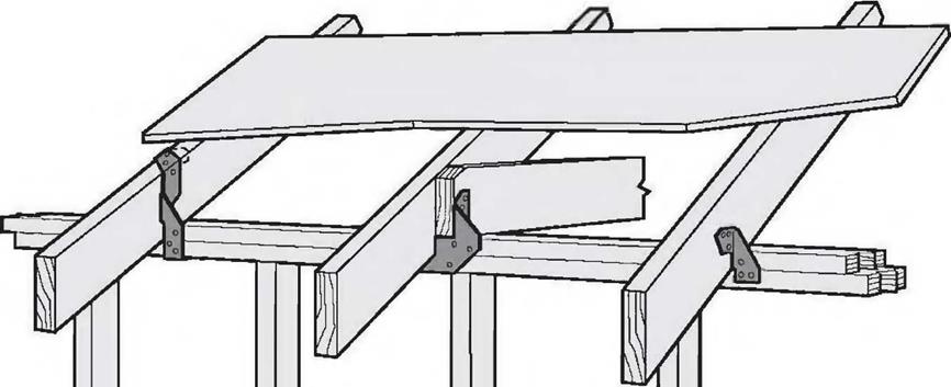
Rafters can be hung on the ridge beam with rafter hangers, but, as the hangers are adjustable for different pitches, they tend to be quite uncommon, as well as expensive.

Another method is to notch the rafters into the ridge beam. At Log End Cottage, we were fortunate that our recycled eight-by-ten ridge beam was already notched to receive the three – by-ten rafters that we recycled from the

same 19th century building in our local village.
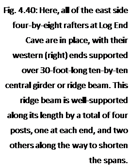
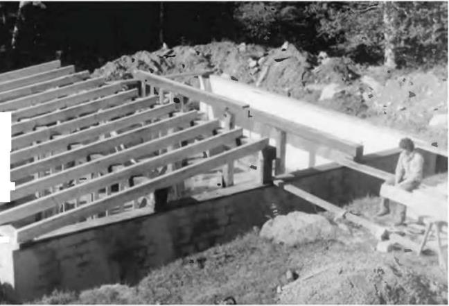
Подпись: Fig. 4.40: Here, all of the east side four-by-eight rafters at Log End Cave are in place, with their western (right) ends supported over 30-foot-long ten-by-ten central girder or ridge beam. This ridge beam is well-supported along its length by a total of four posts, one at each end, and two others along the way to shorten the spans. image82Yet another good method is to join a corresponding pair of rafters over the ridge beam, as we did at Log End Cave. In this case, truss plates on each side of the four-by-eights, at the ridge, can tie each pair of rafters together, or a metal strap can be installed over the top of the rafters, which also serves to tie the rafters to each other. This is important; whatever method of fastening you choose, the rafters must be positively fastened to the ridge beam or to each other to prevent a lateral thrust on the walls. Explanation: The ridge beam cannot move in a downward direction because of the “reactionary load” of the posts, as we saw in Fig. 4.37c. If the

І

rafters are firmly fastened at the ridge,

І »Jtheir top ends cannot move downward

Iw % dpi either. If the tops of the rafters cannot

move downwards, the lower parts of the rafters cannot splay the sidewalls outwards.
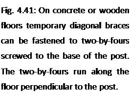
Подпись: Fig. 4.41: On concrete or wooden floors temporary diagonal braces can be fastened to two-by-fours screwed to the base of the post. The two-by-fours run along the floor perpendicular to the post.Fastening rafters to sidewalls using birdsmouths. There are various ways of tying rafters to sidewalls, and the choices may vary depending on roof pitch. One of the most common is the use of “birdsmouths” cut into the rafter. A notch is cut into the rafter so that the rafter bears down flat upon the doubled top plate of stick framing, or upon the girt in heavy timber framing. (The notch resembles a birds open beak, thus the term.) The birdsmouthing method, in combination with toe-nailing or the use of metal right angle fasteners, is a good way to transfer load down to the wall with roof slopes of 2:12 to 12:12. But there are drawbacks:

1. The rafter is weakened when you
Подпись: Fig. 4.42:1 mark the birdsmouth on a four-by-eight rafter by using a template made from a one-by- eight board.image83cut into its cross section in this way, particularly on shear, which is a function of cross – sectional area of the timber.

This weakness is mostly in the overhang.

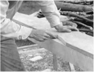
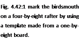
2. It is very easy to make a mistake and cut the birdsmouth at the wrong location. Either the piece is wasted, or there will be some other problem with the build quality if you try to use a miscut member. One would like to think that each piece should be exactly the same, and that a template that works well for one rafter will work for all. In the best of all possible worlds, this is true, but combine rough-cut material with a first­time owner-builder, and the chances of success with a template are pretty slim. By all means, use a template for marking the depth and shape of the cut according to the chosen pitch, but be ready to change the distance spacing of the birdsmouth from the ridge according to actual (not theoretical) measurements. I used a template at Log End Cave (Fig. 4.42), but always checked my measurements for each rafter, sliding the template a little bit, as needed, to accommodate discrepancies.

3. Rafters with birdsmouths in them are not much use for recycling when another builder attempts to recycle your materials two hundred years from now.

4. The cuts are moderately difficult on heavy timbers, such as five-by-tens, something were trying to avoid with timber framing for the rest of us.

You may have guessed that I’m not a big fan of birdsmouths, although I used them on the three-by-ten rafters at Log End Cottage in 1975. I remember that it was a slow tedious process, for reasons already stated in Drawback 2 above. But, in fairness, it must be stated that birdsmouthing is the method that most carpenters use.

Metal connectors are not commonly made for replacing birdsmouthing, and the reason for this may be that connectors would have to be made for a variety of pitches. However, metal tie-down connectors for use in special wind or seismic

image84

L-Ur

image85

Fig. 4.43: A variety of tie-down

connectors. Illustration courtesy of areas are very common and will be required by code in those areas. They can be

Simpson Strong-Tie Co., Inc. used in combination with birdsmouths. Examples of such tie-down connectors

are shown in Fig. 4.43.

Fastening rafters to sidewalls using shims. With shallow-sloped roofs, — say 1:12 to 2:12 — I avoid birdsmouths altogether in favor of shimming with wooden shingles. These shingles, usually white cedar, have a taper to them of about one – quarter in twelve (0.25:12). So four shingles, laid one upon another, yields a 1:12- slope roof, which I like with plank-and-beam earth roofs. The use of shingles with rough-cut timbers has these advantages:

1. It is easy to accommodate different depth dimensions of the rafters with shims. Extra shims can raise “low” rafters so that tops of all are in the same plane, greatly facilitating the installation of planking or plywood.

2. Shimming is much easier to do than birdsmouthing, and yet is still strong, because of the great friction between the rough wood shingles and rough – cut timbers.

3. The use of shims does not weaken the rafters in shear, particularly important with heavy earth roof loads.

ridge gusset

image86


image88

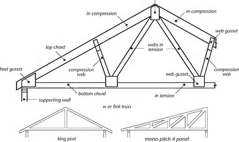
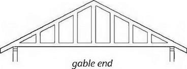
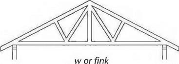
Fig. 4.44: Trusses. Top: Typical W truss, showing its parts and how they work. Bottom: Various truss designs satisfy different needs. Here are just four common ones. Reproduced from Residential Framing by William P. Spence (©1993 by William P. Spence) with permission from Sterling Publishing Co., Inc., NY, NY 10016.


image87

4. A place of common error is eliminated, saving the heartbreak of a wasted timber. (Hey, it’s heartbreak for me, known for squeezing a quarter until the eagle screeches.)

After the rafters are all shimmed and placed in the right locations (which you’ve already marked with pencil on the girt), you can use toenails or right-angle plates to tie them to the wall. Remember that in certain areas, code may require metal straps or metal tie-downs to tie the roof structure to the wall structure, part of the continuous load path already discussed.

Improving Drinking Water Quality with Reverse Osmosis

Pure water is one of the three essentials of life. The Bau-Biology approach is always to look first to nature. For water, we can look to the seagull. In 1969, Steven Sourirajan, professor of environmen­tal studies at the University of California, discov­ered thatthe seagull has a special membrane in its throat that enables it to drink salt water. The mem­brane allows water to be absorbed and the extra salt is then spit out through the nasal passage.

This observation allowed Sourirajan to de­velop the first reverse osmosis water purifier. To­day reverse osmosis has been developed into a marvel of modern water purification technology and is being used all over the world. It has become the most effective method ever invented for wa­ter purification. It out-performs flocculation, distil­lation, carbon filtration, and other methods. Entire city-wide reverse osmosis units have been put into production, sometimes costing hundreds of mil­lions of dollars fora municipal system.

Reverse osmosis units are also being installed in homes. These units need annual servicing for several reasons:

• Filters need cleaning as they collect dirt.

• Reverse osmosis membranes can deteriorate.

• Bacteria can develop in the system.

The reverse osmosis membrane is only one part of this system. Fortruly pure water, there are multiple other filters and steps before and after the reverse osmosis membrane. Reverse osmosis membranes have openings that are too small to be called holes. These pores allow water molecules to pass through but preventthe passage of contaminants. If the filters become plugged with trash, the flow of water is slowed down, reducing the pressure of the water stream, which should be around 60 pounds per square inch. Ideal pressure produces the maximum water purity and best flow and ex­tends the longevity of the components.

In addition to salts, other contaminants are fre­quently found in water and can be effectively re­duced by a reverse osmosis system:

• Heavy metals such as lead, cadmium, mercury, and arsenic, found in all water to varying de­grees, are removed by the reverse osmosis membrane.

• Volatile contaminants such as chlorine, am-

contaminants that can adversely affect public health and are known or anticipated to occur in water.

Secondary standards (NSDWRs) are non­enforceable guidelines for contaminants that may cause cosmetic effects (such as skin or tooth discoloration) or have aesthetic effects (such as taste, odor, or color) in drinking wa­ter. Hie EPA recommends secondary stan­dards but does not require water systems to comply. States may choose to adopt them as enforceable standards.

The EPA Consumer Confidence Rule re­quires public water suppliers that serve the same people year round (community water systems) to provide a consumer confidence report (CCR) to their customers. These re­ports, also known as annual water quality re­ports or drinking water quality reports, sum­marize sources used (rivers, lakes, reservoirs, or aquifers), any detected contaminants, com­pliance efforts, and educational information. The reports are due to customers by July 1 of each year. To find the CCR for your municipal

N


monia, and trihalomethanes are also found in public water supplies and can be removed with pre-and post-filter activated carbon. The carbon also helps remove other volatile indus­trial and agricultural residues such as pesti­cides and herbicides.

• Bacteria are another important concern, but these will typically be killed by the chlorine found in most municipal water systems. Pre­filters will then remove the dead bacteria along with other types of sediment. For puri­fication of water supplies that are not chlori­nated, ultraviolet purifiers can be added to the system to kill bacteria.

Reverse osmosis units should be tested and ser­viced on a regular basis. Annual testing of water quality is a good indicator of how well the unit is functioning and when the reverse osmosis mem­brane needs to be replaced. Poor water quality in some parts of the country means that membranes and filters need to be replaced more frequently there.

Servicing includes not only replacing filters as

necessary but also cleaning and disinfecting the unit. The procedure involves disassembling the re­verse osmosis system, cleaning the unit, flushing it with hydrogen peroxide, replacing the filters, and checking the unit’s performance.

Laboratory water quality tests are only as good as the person doing the evaluation. This means water testing should be performed by a qualified water testing laboratory that specializes in water purification and not just testing. It is of little value to know what is in your water if you do not have a way to remove it.

Warren Clough is a chemist, Certified Water Spe­cialist, and Bau-Biologist with 50 years’experience analyzing water quality and making water purifi­cation system recommendations. His company offers free initial telephone consultations and charges minimal fees for water testing to evaluate reverse osmosis units. It can be reached six days a week during normal business hours at Ozark Water Service and Air Services, 114 Spring Street, Sulphur Springs, AR. 72768, 800-835-8908, ozark waterandair. org.

CASE STUDY 11.1

Countertops for Kitchens and Baths

Most materials in this section require special training and equipment for installation. In fact, solid-surface and stone-polymer countertop mak­ers will sell counter stock only to certified fabri­cators. Some materials, such as plastic laminates, can be successfully installed if you’re handy. But,

image646

image647

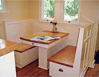
The dining area does double-duty. Both bench seats have built-in hanging file cabinets, so the owner can sit at the table and deal with household bills. And under the butcher-block top, a small end drawer holds flatware.


Countertop Choices

CHARACTERISTIC

PLASTIC

LAMINATE

SOLID

SURFACE

QUARTZ

COMPOSITE

CERAMIC

TILE

STONE

CONCRETE

WOOD

Durability, scratch resistance Fair

Excellent*

Excellent

Good

Goodt

Good

Fair!

Ease of cleaning

Excellent

Excellent

Excellent

Fair§

Excellent

Good

Fair

Stain resistance

Good

Good

Excellent

Fair

Fair

Poor

Poor

Water resistance

Good

Excellent

Excellent

Fair

Good

Good

Poor

Heat resistance

Poor

Fair

Good

Excellent

Excellent

Excellent

Poor

Expense

$

$$$

$$ to $$$

$$

$$$

$ to $$

$$

Material scratches, but scratches are easily sanded out. f Durability depends on type of wood and finish; wood is generally a bad choice near sinks and water. t Harder stones (granite) wear well; softer stones (soapstone) scratch and stain easily.

§ Glazed tiles resist stains, water, and heat; but grout joints deteriorate if not sealed and maintained.

as you’ll see, desirable details, such as wrapped front edges and integral backsplashes (no seams to leak!), are best fabricated in a pro shop. All in all, it’s smarter to choose a reputable installer than to try installing a countertop yourself. Tile countertops are discussed in Chapter 16.

CHOOSING COUNTERTOPS WISELY

The wide array of countertop colors, materials, and details (such as edges and backsplashes), give you tens of thousands of combinations to choose from. Here’s help narrowing your choices.

Plastic laminate, a tried-and-true surface (often called Formica® after a popular brand), accounts for more than two-thirds of all coun­tertop installations. Standard laminate is only Мб-in. thick, so it is typically glued to a %-in. particleboard substrate to lend rigidity and ensure adequate support. Plastic laminate remains so popular because it’s tough, stain – resistant, quite economical, and available in a great range of colors and patterns. There are also extra-thick and fire-resistant laminates.

One disadvantage is that the seams can degrade and admit water. And once the substrate is water damaged and the laminate is lifting, the countertop is beyond repair.

Solid-surface countertops began with DuPont’s Corian®, which is still the best-seller in this category. Most brands are polyester or acrylic resins with a mineral filler. Solid-surface countertops have a lot going for them: They’re water and stain resistant; nonporous and easy to clean and thus great for food prep; and leakproof because they have seamless, chemi­cally bonded backsplashes and integral sinks. Unlike laminates, solid-surface sheets are the same material top to bottom, so if you scratch them or put too hot a pot on them, you can sand out the blemishes. Most brands come with a 10-year warranty. Note that this material is gen­erally expensive.

Quartz composites are a new and rapidly grow­ing group that includes brands such as Zodiaq® and Silestone®; the blend is roughly 93 percent quartz and 7 percent polymers and pigments. Quartz composites have many of the virtues of stone countertops and few of the failings. Quartz composites are scratch, heat, and stain resistant; completely nonporous so they’re easy to clean; and less likely to fracture during transit because mineral particles are uniformly dispersed and free from the imperfections of natural stone.

Plus, a 10-year warranty is standard. However, these composites are expensive. And stone con­noisseurs will know the countertop is not natural stone because of its uniformity.

Ceramic tile is beautiful and durable. Its great variety of colors, shapes, and sizes allows almost unlimited freedom to create your own patterns. Glazed tiles themselves are largely resistant to heat, water, stains, and scratches. Tile can be applied successively over a plywood substrate or a mortar bed, and a diligent novice can install it successfully. Tile prices vary widely, and thus can fit almost any budget. But its grout joints are rel­atively fragile, easily stained if they’re not sealed and maintained, and tend to collect crud. Also,

INSTALLING WALL CABINETS

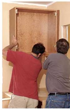
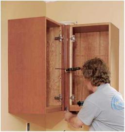
Wall cabinets must be leveled, plumbed, and solidly anchored, so transfer the locations of stud centers to the back of each wall cabinet, and predrill screw holes in the mounting rails, as you did for base cabinets. Remove the doors and shelves so the cabinets will be easier to lift and position next to the alignment marks you drew earlier along the wall cabinet layout line. Before lifting anything, however, use a 6-ft. spirit level to refresh your memory as to where the wall’s surface is out of plumb and where it bulges or recedes. Make light pencil notations on the wall.

Supporting cabinets. It’s better to have a helper hold wall cabinets in place as you mount them. But if you’re working solo, the simplest support is a temporary support strip, a straight, predrilled M-in. by Hi-in. plywood strip placed immediately below the wall cabinet layout line and screwed to each stud with a #8 wood screw (see "Cabinet-Mounting and Edge Details,” on p. 306). With the cabinet bottom sitting atop it, the strip will support the box’s weight, freeing one of your hands to screw the top mounting rail to a stud. That first screw will hold the cabi­net in place, but don’t sink it so deep that it bends the mounting rail.

Plumbing and shimming. Once that first screw is in, the cabinet should stay put, so you’ll have both hands free to shim the cabinet and check for plumb. A cabinet sitting on a leveled strip should have a level bottom and plumb sides— but check to be sure. The front of the cabinet must also be plumb. So if it’s not, insert shims between the wall and the cabinet. Although you can easily shim behind the top mounting rail, the support strip will prevent shimming from underneath; instead, shim the bottom corners from the side. If the top of the cabinet needs to come forward, slightly back out the screw in the top mounting rail. Once all the cabinet faces are plumb, drive a second screw through the top mounting rail and a third screw through the bot­tom rail, near the shim point. You will add another screw to the bottom rail later, after you remove the support strip and shim behind the fourth corner of the cabinet box.

Ideally, each wall cabinet should be secured to at least two studs with two #8 wood screws through the top mounting rail and two screws through the bottom rail. However, many wall cabinets are too narrow to reach two studs. Screwing cabinet boxes to each other lends addi­tional support and spreads the load. But if a cabi­net will be heavily loaded or if you’re uneasy

SCRIBING A PANEL TO AN IRREGULAR WALL

image644

Hanging wall cabinets is easiest with four hands: Two hold and adjust, while two check level and drive screws.


image642

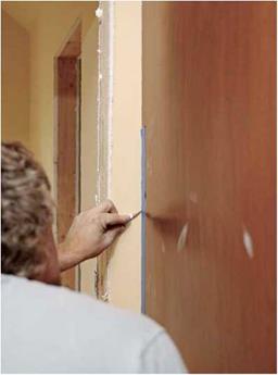
To scribe an end panel (here, a refrigerator panel), first level and plumb its edges. Put painter’s masking tape on the panel and scribe directly onto the tape to make the line more visible. If the wall irregularity is slight, hold a pencil flat to the wall and slide it up and down.


image643

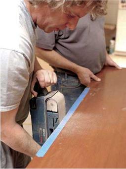
A belt sander held 90° to a scribed line enables you to see how much wood you’re removing.

Use a 120-grit belt, back-bevel the edge slightly, keep the sander moving, and stop just shy of the line. Finish off with a sanding block or a handplane.


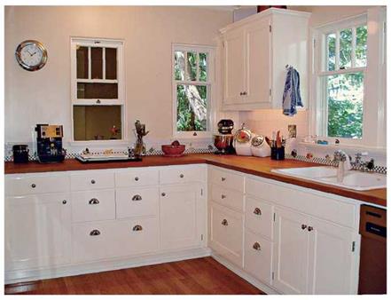
Подпись: In this Eugene, Oregon, bungalow, you're more aware of individual elements because painted base cabinets offer a nice contrast to the red oak floors and maple butcher- block countertops. The traditional enameled cast-iron sink continues the contrast-and-enjoy scheme.Подпись:image645

hanging it on only one stud, cut open the wall and let in (mortise) a piece of 1 x blocking into at least two studs. You’ll need to repair the wall—a rough patch is fine if it’s hidden by cabinets—but you’ll have plenty to screw to.

Tying cabinets together. Install the wall cabi­nets in roughly the same order you did base cabinets. If the cabinet layout is L – or U-shaped, start with a corner cabinet and work outward.

As you set successive cabinets, place a straight­edge or a 6-ft. level held on-edge across several cabinet faces to make sure they’re flush. You may need to back out screws or drive them deep­er to make the cabinets flush. Once they’re flush, clamp and screw them together as you did for the base cabinets. At that point, you can remove the support strip. With the strip gone, the space
behind the bottom mounting rail will be accessi­ble, so add shims and screws as needed.

Finishing touches. Patch holes left by the support-strip screws or cover them with trim. Custom cabinetmakers often use a piece of trim with the same finish as the cabinets as a support strip and just leave it in place. Thus if the front of the cabinet has a 1 %-in.-wide trim piece running along the bottom to hide a light­ing strip, use a piece of HCin.-wide trim as a support strip. Cover the cabinet-mounting screws with wood plugs or stick-on screw cov­ers. Finally, install the shelves, drawers, doors, and hardware such as pulls or knobs.

These days, most cabinets use European – style door hinges (shown at left), which are easy to remove, reattach, and adjust. Hinges are set into 35mm-diameter holes bored precisely into the door frames. The doors are attached to the cabinet box via baseplates; these hinges easily clip on and off the baseplates without the need to remove any screws. Once the cabinets are installed, clip on the doors and use the adjust­ment screws to raise the hinges up or down, in or out, until the reveals (gaps) between the doors are equal and the doors lie flat.

Transverse porosity

Transverse (or lateral) porosity can often be seen on pavements made during unfa­vorable weather conditions (in autumn or in winter) or when the mixture has been

image134

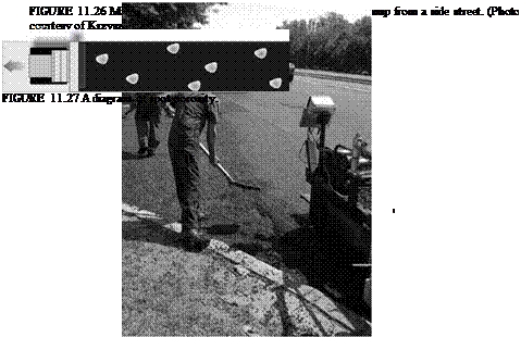
FIGuRE 11.25 Beginning of a work site—effect shown years later, a consequence of spreading too cool a mixture at the beginning of the work site. (Photo courtesy of Krzysztof BlaZejowski.)

image135215

Подпись: <68

image136

153

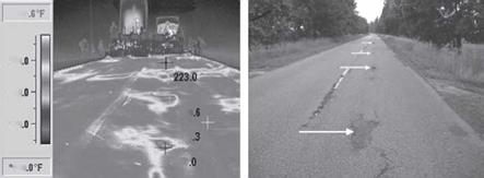
FIGURE 11.28 Local porosities: (a) an infrared image; (b) the effects after a couple of years on another road that has the same problem, arrows point at spots of pavement pot holes occurring at cyclic distances. (Photos [a] courtesy of Kim A. Willoughby, WSDOT, United States; [b] courtesy of Krzysztof Blazejowski.)
transported from far away. It has the distinctive appearance of transverse strips with increased porosity (Figure 11.29).

The most common cause of this is the buildup of cool mixture at the wings of the paver hopper. The distance between the strips of porosity in Figures 11.30 and 11.31 more or less reflects the distances between the loading places of fresh mixture into the paver from end dump trucks. This develops when the paver crew lifts the

image138

FIGURE 11.29 A diagram of transverse porosity.

image139

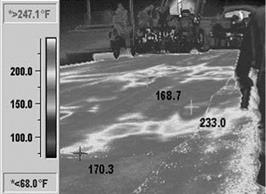
FIGURE 11.30 Infrared images showing porosity in the form of transverse, cyclic strips, tem­perature in degrees Fahrenheit. (Photo courtesy of Kim A. Willoughby, WSDOT, United States.)

image140

FIGURE 11.31 An example of cyclic strips of transverse porosity on a new SMA course. (Photo courtesy of Krzysztof BlaZejowski.)

hopper’s wings to use all of the previously delivered material before accepting a new delivery. Since the older mixture is significantly lower in temperature, after it passes through the paver this cool mixture appears as a transverse streak of porous (cold) material behind the screed.

Various preventive methods may be used to avoid this porosity, including the following:

• Paver staff should regularly remove the mixture residue on hopper wings or leave that mixture in the hopper wings until the end of the day, when it can be removed and disposed of.

• Complete unloading should not be allowed; the fresh, hot mixture should be unloaded from the truck to the hopper while some of the previous delivery of mixture is left in the hopper.

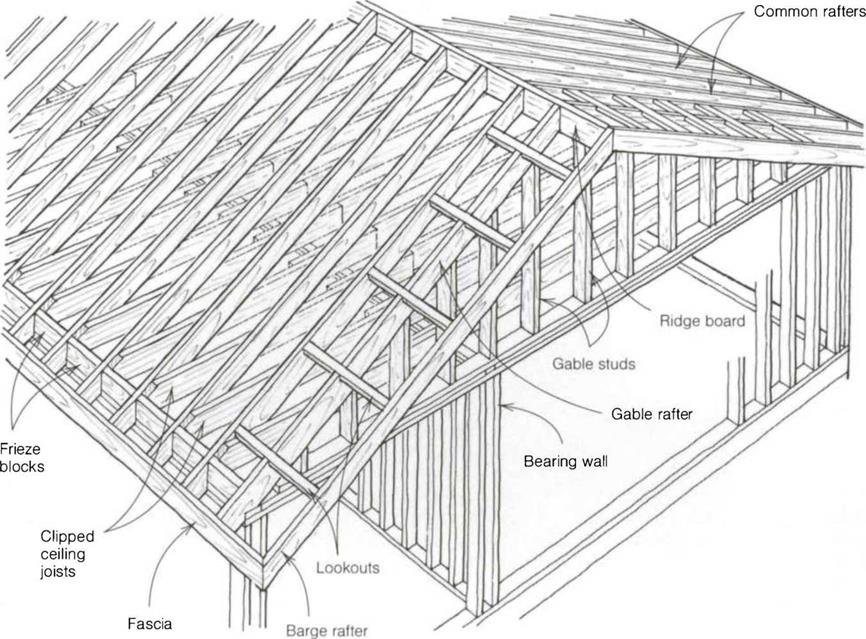
The parts of a gable roof

The parts of a gable roof

the span. When you know the pitch of a roof plus the true span (measure the span from outside wall to outside wall with a long tape) or the run, you can determine the length of the common rafters. To do this, try using a book of rafter tables (see Sources on p. 198) or a pocket calculator.

A 24-ft.-wide building has a span of 24 ft. To find the rafter length of a 4-in – 12 pitch roof for this building, open your rafter-table book to the 4-in-12 page and look under the common-rafter table
at 24 ft. to see that the rafter length is 12 ft. 73/д in. If the span is 24 ft. 8 in., look under 8 in the inches column and add on an extra 41A in. That is the total length of the common rafter. It’s really that simple, so don’t make it difficult for yourself. After a few minutes with a rafter book, you can figure the length of almost any rafter for any pitch and any span. Subtract from this figure half the thickness of the ridge board (3A in. for a 2x ridge) and leave enough extra wood to cover the length of the tails in the overhang.

The great reservoirs of Ceylon

About 544 BC the island of Ceylon (Sri Lanka) falls under the domination of princely families of Indo-European origin, coming from Maghada. The Ceylonese civilization develops markedly after the conversion of the island to Buddhism. This conversion is attributed to a certain Mahendra who, according to tradition, is said to be the son or the brother of the great king Afoka. Irrigation is a significant factor in the island’s develop­ment. Rainfall is abundant, but concentrated during the monsoon period. Since the soil is relatively impervious, very little of the rain is stored as groundwater. The only solu­tion is construction of dam-reservoirs.

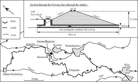
We can identify several reservoir-dam installations dating from 370 BC to 540 AD. They range in height from 5 to 20 m, and some are several kilometers long.[301] Eight of them are in the region of the capital Anuradhapura; three in the region of the great south­ern city, Magama, and four more near Polonnaruwa, which becomes the capital of the island after 781. All of these are earthen dams of trapezoidal section (Figure 7.3), fair­ly narrow at the top. The talus slope was rather steep for the first of these dams (370 BC), being 1:2.5 on both the upstream and downstream faces. Subsequent dams had somewhat flatter slopes, generally 1:3 on the downstream face (and in unusual cases, 1:5). These rather long dams are not rectilinear, but follow the terrain in such a way as to minimize their height and maximize the volume of stored water – which can be mul­tiples of ten million cubic meters for the larger reservoirs. One dam near Polonnaruwa is an exception to this general configuration. It is relatively short, but is built to a height of 17 m at the time of its initial construction in around 300 BC, and then is raised to 34 m in 460 AD. Depending on the dam, floodwaters are spilled either over a natural rocky sill, or over a thick stone wall covered with a layer of large blocks. Often several dams are built on the same river, or on different tributaries of the same watershed. From the 5th century AD, canals that are 15 to 30 km long transfer water from one valley to anoth­er within the same overall watershed.

One of the reservoir-dam installations in the northwest portion of the island is gigan­tic, having an immense reservoir of 39 million cubic meters. The reservoir is contained by a semi-circular dike that is 9 km long. This project was first undertaken in the 12th century AD by the king Parakrama Bahu, but it remained unfinished, the necessary efforts exceeding the capacities of the population. Eventually Tamil invaders, coming from the south of the Indian subcontinent, replace the authoritarian dynasty that had developed such vast hydraulic resources for the island of Ceylon. The Tamils neither maintain nor further develop the hydraulic systems, which therefore progressively fall into decay and ruin.

The great reservoirs of Ceylon

Figure 7.3 Development of the basin of the river Malwatu near the ancient capital of Ceylon, Anuradhapura. The first man-made reservoirs are those of Bassawak and Tissa (about 300 BC), then Nuwara (80 BC), Balalu (40 BC), Mahawilachchiya (70 AD), then Kala and Tirappane (around 470 AD) and Machchaduwa (540 AD). The sketch shows the state of the development at the end of the 6th century AD, and the structural details of the Nuwara dam, 4.8 km long, creating a reservoir of 43 million cubic meters. After Schnitter (1994).

KEEPING COLD AIR FROM ENTERING. AT THE RIM JOISTS

Подпись: To keep cold air from entering on top of the floor insulation, ensure that insulation is right up against the subfloor (above, left) or roll the insulation up the inside of the rim joist to the subfloor (above, right). Either of these techniques will help prevent a cold floor. Helping Hand

Store fiberglass scraps in a garbage bag. Spare and scrap pieces of fiberglass can easily blow all over a job site. To keep this fluffy material under control, put it in a large plastic garbage bag. Partial rolls can also be stored in a plastic bag until needed.

Подпись: SUPPORTING INSULATION BETWEEN FLOOR JOISTSПодпись:Подпись: InsulationПодпись: Wood lath nailed to the bottom of the floor joists 12 in. to 16 in. o.c.Подпись: Metal rods between joists about every 12 in. o.c.Подпись: Plastic mesh or landscape cloth stapled to the underside of the joistsKEEPING COLD AIR FROM ENTERING. AT THE RIM JOISTS

STEP 3 Install Vapor Barriers (if Necessary)

Unlike housewrap, a properly installed vapor barrier is supposed to be impermeable. Vapor should not pass through it. Different materials are used as vapor barriers. The kraft-paper facing on fiberglass batt insulation is designed to function as a vapor barrier. To form a con­tinuous barrier, the paper flanges must over­lap on the sStud face, where they are stapled in place. Polyethylene sheeting is also commonly used as a vapor barrier. Thin (6 mil), clear “poly” sheet material is stapled to the face of studs, attic joists, and (on cathedral ceilings) rafters. The barrier is kept continuous by overlapping adjoining sheets and sealing the overlap with silicone or another sealant.

Its much easier to describe what a vapor barrier does than to explain why it is essential in some situations but not in others. I once

Techniques THE AC ALTERNATIVE: A WHOLE-HOUSE EXHAUST FAN

KEEPING COLD AIR FROM ENTERING. AT THE RIM JOISTSПодпись: COOLING WITH A WHOLE-HOUSE FANПодпись: Ridge ventПодпись: WindowsПодпись: A fan pulls in cool night air through the windows and pushes hot air that has built up during the day through the gable-end or ridge vents.Подпись: WindowsKEEPING COLD AIR FROM ENTERING. AT THE RIM JOISTSПодпись:Подпись: Insulated fan cover for winter monthsПодпись: Placed in a central location, a whole- house fan can cool a small house quickly.KEEPING COLD AIR FROM ENTERING. AT THE RIM JOISTS

ALTHOUGH IT IS NOT IDEAL in all cli­mates or seasons, a whole-house fan can be a very attractive alternative to air – conditioning. A simple fan is more reliable and less expensive than a single window – mounted AC unit, and it can effectively cool an entire house. As shown in the illus­tration at right, the principle is simple: A single, centrally located fan pulls in fresh air through open windows and blows hot indoor air outside. By turning the fan on in the evening and opening all major win­dows, it’s possible to quickly cool a house that has become hot during the day.

These fans work best in dry climates, or at least when the air is cool and dry out­doors. In the winter, when the fan is not being used, it must be protected with an insulated cover to prevent heated air from entering the attic space. I make a simple cover from plywood and then glue several layers of rigid foam to the top and sides.

had to tear out an entire wall that had rotted because the house had no vapor barrier. There was so much water trapped in the walls that you could literally wring it out of the insula­tion. A vapor barrier would have prevented such damage.

To understand why and where a vapor barrier is important, imagine what happens when someone takes a long, hot shower in your home when its freezing cold outside.

The bathroom is foggy with water vapor, and some of that warm, humid air makes its way into the attic and the exterior walls. The air can easily pass through openings around electrical outlets and light fixtures and even
through the gypsum board itself, which absorbs moisture readily. At some point, the temperature in the attic and the exterior walls drops enough to cause condensation. This dew point can occur in the middle of the attic or wall insulation or against roof and wall sheathing. Over the course of a cold winter, a steady supply of moist interior air can easily accumulate, causing soggy insulation, mold, and rotten wood.

A vapor barrier prevents the movement of vapor from a warm area to a cold surface. In cold climates, it should definitely be installed right underneath the drywall, paneling, or other interior wall finish material. Instructions

KEEPING COLD AIR FROM ENTERING. AT THE RIM JOISTS

STEP 2 INSULATE THE WALLS, CEILINGS, AND FLOORS

Although the reason for sealing cracks and gaps in a house frame may be fairly obvious—you don’t want cold breezes (or hot air, depend­ing on where you live) blowing through the house—the function of insulation may not be as evident. It is not to block airflow but rather to create pockets of dead air. Air pockets do the actual insulating work, whereas the insula­tion fibers or beads simply hold the air in place. That’s why jamming fiberglass insulation into a too-small space isn’t very helpful. In fact, doing so just eliminates much of the air space within the material, effectively reducing its value as insulation.

There are a number of materials used for insulation, but the three most common ones are cellulose, rigid foam, and fiberglass.

Subcontractors most often install cellulose in­sulation by blowing the loose material into attics with special equipment (see the sidebar at left). When binders are added to cellulose insulation, it can also be sprayed in dampened form between studs. When it is properly applied, the insula­tion stays in place after the moisture evaporates. Unlike fiberglass insulation, which demands