Stair & Ramp Framing

The width of stairs must be a minimum of 36” from finish to finish. Handrails may project into the 36” a maximum of 4%" on each side. (See “Stairs" illustration.)

Two sets of tread and riser dimensions apply to minimum and maximum requirement. One set is for Group R-3, Group R-2, and Group 4 (houses, apartments, dormitories, non-transient housing).

The other is for all other groups. The first set requires a maximum riser height of 7%" and a minimum
tread depth of 10”, while the second requires a maximum riser height of 7”, a minimum riser height of 4”, and a minimum tread depth of 11”.

The variation in riser height within any flight of stairs must not be more than 3/s” from finish tread to finish tread. The variation in tread depth within any flight of stairs cannot be more than 3/s” from the finish riser to the nose of the tread.

Headroom for stairways must have a minimum finish clearance of 6′-8”, measured vertically from a line connecting the edge of the nosings.

Handrails may not project more than 4.5 inches on either side. 44” minimum if occupant load is 5o or more. Large buildings: Minimum equals occupant load multiplied by.3 inches per occupant but total not less than 44".

The difference in the largest tread or riser cannot be more than 3/s" bigger than the smallest tread or riser. Stairs with solid risers are required to have tread nosing not less than %" or more than Ш"

Handrails for stairs must have a height of no less than 34" and no more than 38", measured vertically from a line created by joining the nosing on the treads.

Stairway landings must be provided for each stairway at the top and bottom. The width each way of the landing must not be less than the width of the stairway it serves. The landing’s minimum dimension in the direction of travel cannot be less than 36", but does not need to be greater than 48" for a stair having a straight run. (See “Stair Landing" illustration.)

Circular stairways should have a minimum tread depth at a point 12" from the edge of the tread at its narrowest point of not less than 11". According to both the IRC and the IBC, the minimum depth at any point must be 6". (See “Circular Stairs" illustration.)

Spiral stairways must have a minimum width of 26". Each tread must have a minimum tread width of 71/г" at a point 12" from the narrow edge

of the tread. The rise must be no more than 9%". All treads must be identical. The headroom is a minimum of 6′-6". (See “Spiral Stairs" illustration.)

The maximum slope on a ramp is 8%, or one unit of rise for 12 units of run. Some exceptions (where technically infeasible) are available for slope of 1 unit vertical in 8 units horizontal-12-%%. Handrails must be provided when the slope exceeds 8.33%, or one unit of rise and 12 units of run.

The minimum headroom on any part of a ramp is 6′-8".

A minimum 36" x 36" landing is required at the top and bottom of a ramp and where there is any door, or where the ramp changes direction. The actual minimum landing dimensions will depend on the building use and occupant capacity. This minimum does not apply to non-accessible housing.

The maximum total rise of any ramp cannot be more than 30" between level landings. (See “Ramps" illustration later in this chapter.)

If the building’s occupancy capacity is more than 50, then the minimum landing dimensions are 44".

The actual minimum landing dimensions will depend on the building use and occupant capacity.

Ventilation

Ventilation is required so that condensation does not occur on the structural wood, causing dry rot and the deterioration of the building. Cross ventilation is required in crawl spaces, attics, and in enclosed rafter spaces. In rafter spaces between the insulation and the roof sheathing, there must be at least 1" clear space.

The total area of the space to be ventilated cannot be more than 150 times the size of the area of the venting. (Both are measured in square feet.)

MAINTENANCE AND CONSTRUCTION OF SIGN SUPPORTS

An important element of a safe highway environment is the proper construction and maintenance of traffic signs. Good designs and the best of materials will not be effective in reducing accident potential or severity if the traffic signs are improperly placed or installed. This requires that field crews be knowledgeable of proper installation tech­niques and that they report and correct any possible problems instead of merely placing the signs at the roadside. (See also Art. 7.1.2.)

7.6.1 Proper Placement

Important considerations for proper placement include the following:

• Warning signs should be placed sufficiently in advance that the driver has adequate time to perceive, identify, decide, and perform any necessary maneuver. A guide for the placement distance of warning signs is contained in MUTCD [2].

• The MUTCD provides guidelines on the height and lateral placement of typical sign installations. Signs installed on the side of the road in rural districts should be at least 5 ft (1500 mm) measured from the bottom of the sign to the near edge of pave­ment. In urban districts or where parking or pedestrian movements occur, the clear­ance to the bottom of the sign should be at least 7 ft (2100 mm). Ground-mounted signs on freeways and expressways should be at least 7 ft (2100 mm) above the level of the pavement edge and have the minimum lateral offset of 12 ft (3700 mm) from the edge of the traveled way. If a shoulder wider than 6 ft (1800 mm) exists, the minimum lateral offset for ground-mounted signs should be 6 ft (1800 mm) from the edge of the shoulder.

• All sign assemblies located within the traversable area must be capable of giving way safely upon impact. This requires that the maximum vehicle deceleration does not exceed 16 ft/s (5 m/s) and that the sign assembly does not protrude into the pas­senger compartment [14].

• Sign supports installed with anchor systems must have a maximum height of 4 in (100 mm) from ground level to the topmost part of the anchor.

• Most sign-support assemblies are designed to function properly when impacted at bumper height, typically about 20 in (500 mm) above the ground. If impacted at a higher point, the assembly may bind at the planned shear point resulting in nonacti­vation of the breakaway mechanism. For this reason, it is critical that breakaway sign assemblies not be located near ditches or on steep slopes or other locations where the vehicle can become partially airborne at the time of impact.

• Sign supports should not be placed in ditches. The water in the ditch can erode the soil around the base of the support, cause premature deterioration of the post, and freeze, resulting in unpredictable performance during impact. The ditch can also act as a guideway that directs errant vehicles into the sign assembly.

• Sign-support assemblies are tested in both strong and weak soils. Supports that are designed to yield, or fracture, upon impact generally perform better in strong soil. Strong soil holds the buried portion in position, providing sufficient resistance for the sign support to break near ground level. Weak soils do not provide this resistance, but permit movement within the ground and unpredictable results. Yielding or fracturing supports that are embedded less than 40 in (1000 mm) in weak soil will often pull out of the soil. While this may provide acceptable impact performance, the force of the wind and ice loads may cause the sign assembly to rotate or fall down. The actual soil type that is present may not be known until the start of installation. Weak soils are those that offer relatively little resistance to driving the signpost. If weak soils are encountered, there are measures that can be taken to maintain sign orientation in the face of environ­mental loads and still result in proper operation during impact. These include embedding the signpost to 40 in (1000 mm), and the use of anchor plates, concrete footings, and commercially available anchor systems [34].

• Single-sign-support systems are designed to operate safely when only one support is struck upon impact. Tests have shown that an errant vehicle, leaving the roadway at an angle, can impact more than one support if supports are not separated by more than 7 ft (2100 mm). This separation applies to other fixed objects as well as signposts. For example, a 3-in-diameter (75-mm) tree is sufficiently small to provide accept­able impact performance. Installing a sign support 6.5 ft (2000 mm) from this tree, however, can result in an errant vehicle’s impacting both the tree and the signpost. The combined effect of the tree and sign can provide unacceptable impact performance.

• Multiple-mount sign supports are required to support sign panels that are too large to withstand wind and ice loads with the use of only one support. Multiple-mount sign supports are designed to provide acceptable performance upon impact when the supports are placed 7 ft (2100 mm) or closer to each other. This close spacing results in the possibility that a vehicle leaving the roadway at an angle will impact two or more supports simultaneously. This possibility means that some supports approved for use in a single-support system are not approved for multimount designs. Support configurations that have not been approved for use as multiple – mount systems should not be used for multimount sign supports until they have been approved by the FHWA.

• Study the traffic patterns and surrounding geometrics prior to installing any sign. If the sign assembly can be expected to be struck from more than one direction, then a unidirectional slip base design is an improper choice. Two-lane rural roadways should use roadside supports that function safely when impacted from two direc­tions. Installations on freeways, with wide medians or positive median barriers, can be expected to be impacted from only one direction.

• In summary, be aware of what is required for sign installations to function properly for both the environmental loads and vehicle impact. Do not install a device simply because it has been specified on the sign order. The actual site conditions may have been unknown, or different from what was expected by the designer who specified the type of sign assembly. If problems are identified, contact a supervisor to deter­mine if changes should be made.

LAYING OUT CABINETS

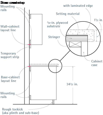
Using a long level atop a straightedge, locate the high point of the floor. It’s easier to set a base cabinet (or rough toekick) at the floor’s high point and shim up the other cabinets to that level than it is to cut down cabinet bases and toekicks. From the floor’s high point, measure up the height of a base cabinet (usually 34h in. high) and mark the wall. Use a laser level, as shown in the top left photo on p. 45, to transfer the base cabinet mark to other walls, creating a level line around the room, which we’ll call the base cabi­net layout line.

Marking off elements. Along the base cabinet layout line, mark off fixed elements, such as the stove, range hood, and refrigerator. Often, a sink cabinet will center under a window. If upper cab­inets are to frame a window evenly on both sides, mark the edges of those cabinets. Once the large elements are marked onto the walls, mark off the widths of the individual cabinets. For frameless cabinets, measure from the outside of the side panels. The frames of face-frame cabinets extend slightly beyond the side panels, creating slight gaps between the boxes. Much of the time, the sides of wall and base cabinet units will line up vertically because they are the same width.

Wall cabinets. Use the base cabinet layout line to establish the bottoms of wall cabinets, too. Because wall cabinets are normally placed 18 in. above the finish countertop, measure 19h in. up from the base cabinet layout line to position the bottoms of the wall cabinets; shoot a laser level through that mark and lightly pencil a second level line around the room, which is the wall cab­inet layout line. Over refrigerators and stoves, the bottoms of the wall cabinets will be higher. If you are also installing full-height pantry or broom cabinets, make sure their tops align with the tops of the wall cabinets; if they don’t, raise or lower the wall cabinets till the tops line up. Next mark off the width of the wall cabinets along the wall cabinet layout line.

Scribe locations. Layout marks should also include scribe locations, where you must install a narrow scribe piece (filler strip) to cover a gap between cabinets and an appliance or a space between an end cabinet and an irregular wall. Where cabinets meet at inside corners, 1 h-in.- or 2-in.-wide scribes are often needed to offset drawers or doors slightly, so they have room to pull past the cabinet knobs or appliance handles sticking out from the adjacent bank of cabinets.

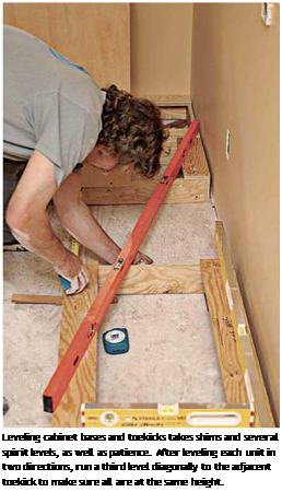
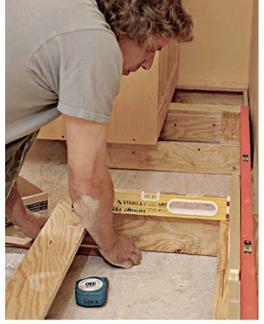
Подпись: Leveling cabinet bases and toekicks takes shims and several spirit levels, as well as patience. After leveling each unit in two directions, run a third level diagonally to the adjacent toekick to make sure all are at the same height. Подпись: To make rough toekicks, rip down 3/4-in. plywood, which is more durable and water resistant than particleboard should there be a leak. Don't use 2x4s because they are rarely straight enough to use as a sub-base for cabinets. Besides, rough toekicks must be 4 in. high, and a modern 2x4 placed on edge would be just 31/ in. high. 1111

Подпись: INSTALL THE loekick FIRST If finish floors aren't yet installed and you don't want the cabinets dinged up by the flooring installers, then install only the toekick initially, shimming it level and screwing it to the subfloor. This is especially recommended if you'll be laying tile floors because mortar and grout are messy. Then flooring installers can run the flooring snug to the toekick, covering the shims. When the flooring is complete, simply place the base cabinets atop the level toekick and screw them down. When constructing the toekick, increase its height by the thickness of the finish floor, so the top of the toekick will be 4 in. above the finish floor. If you're installing tile over a mortar bed (1 in. to l1/ in. thick), make the rough toekick 5 in. to 51/ in. high.

Marking studs. Finally, find and mark stud cen­ters, to which you’ll screw the cabinets. To find studs, either use an electronic stud-finder, rap the walls with your knuckles, or drive small finish nails into wall areas that will be covered by cabi­nets. Whatever works! Use a spirit level to plumb light pencil lines that indicate the stud centers. It’s desirable to screw into as many studs as you can to secure wall cabinets, but screwing into only one stud is acceptable for base cabinets and for narrow wall cabinets that don’t reach two studs.

Roof Systems

There are basically two different roof-support systems that are appropriate for use with timber framing. Most timber framers continue on with additional timber framing, and I have done this, as well, at Log End Cottage, Log End Cave, and Earthwood, by using methods described in this book. The other support system that should be considered carefully is the truss-supported roof, like the garage at Earthwood and the one that Chris built.

Is one system better than the other? Not necessarily. There are pros and cons for each.

i. Engineering. Trusses are normally designed and built by professionals.

I’m not saying that owner-builders have never done it, and successfully, but, like mixing one’s own concrete, it is hardly worth the effort for the money saved. Engineering is crucial. You would need to use a standard truss design that happens to suit the dimensions and purpose of your building, or have the trusses professionally engineered. Then you’d need to create a large template, such as on a barn floor, to actually fasten the various chords together with truss plates. Purchased trusses are not that

image80

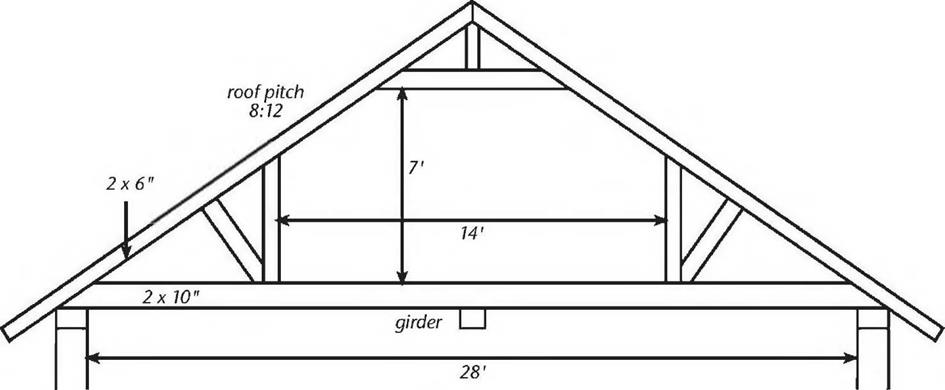
expensive, and the manufacturers know how to design a truss for your Fig. 4.38: Richard Flatau’s attic

application. trusses looked something like this.

The engineering of a timber-framed roof is a bit more basic, and timber frame designs tend to be on the over-built side, anyway. With a rafter system, you can consult span tables to find appropriate timber size.

Still, unless you are following a tried and proven plan, you should have your entire timber-frame plan checked by a structural engineer. And strong jointing, both at the top and the bottom of the rafter, is critical.

2. Upstairs space. With timber framing, it is, perhaps, a little easier to create useful space under the roof, although there is a truss design, called “attic trusses” which can afford some space upstairs, usually a little less than half of the entire area of the ceiling below. Richard Flatau used attic trusses with his post-and-beam cordwood home in Merrill, Wisconsin. The company that engineered, built, and delivered the trusses also put them up onto the girts. Their delivery truck has a boom built onto it for the purpose. Richard hired a contractor friend experienced in truss work and enlisted a couple of other friends as “grunts,” and the 20 heavy trusses were installed in just two hours. Richard says that the trusses enclose 560 square feet (52 square meters) of extra living space upstairs, including two bedrooms, a play area, ample storage, and a half bath. See Fig. 4.38.

3. Ease of construction. By the time the girts are in place, timber-framing the roof structure will be an extension of using many of the same

techniques with which the builder is already familiar, although there will be a few new ones. Trusses are an entirely different kettle of fish, but installing trusses is not that difficult, particularly if you follow Richard Flatau’s example and hire one person with experience to tell you and your other helpers what to do.

Trusses can be installed with or without the use of a crane. Chris Ryan simply had his garage trusses delivered to site, and he and two friends were able to hang them upside down between the parallel sidewalls by themselves. (Fig. 4.46 on page 97). Later, with a man at the top of each side wall, a third person with a long pole would “flip” a truss upright, and then, from a ladder, help the team space and brace the truss into position. It is really important that the trusses be square on the girt system, parallel to each other, and exactly at the planned regular spacing, usually 16 or 24 inches on center.

Using a framing square, you should mark the top of each girt, showing each edge of each truss. Make sure the spacing comes out right on both sides. Spacing is critical if you are planning to nail plywood on top, or sheetrock ceilings to the underside of the trusses. Squareness and plumb are both part of the all-important build quality.

On balance, and assuming that you find someone with experience to help, I’d say that trusses are probably quicker and easier than timber framing.

Incidentally, traditional timber framers often create what can be described as timber-framed trusses, which they raise like bents on the day of the timber raising, as we saw back in Fig. 2.17. Conventional timber framers — the rest of us — usually install each member individually.

4. Cost. Richard Flatau says that his attic trusses actually cost $800 less (1979 prices) than the cost of a conventional “stick-built” roof. The total cost of his 20 trusses, delivered and placed on the girts, was $1,400 in 1979. These were large, heavy trusses, suitable to support floor loads upstairs. I think it is safe to just about triple the cost of those trusses today. Our garage trusses span 24 feet and have two-foot overhangs each side, and cost us $58 each in 1998. But Richard’s trusses were made from two-by-sixes and two – by-tens, while all parts of our trusses are two-by-fours. It is difficult to compare truss cost to timber-frame cost, as the cost of the timbers themselves varies so widely from one project to another, depending on

how the timbers were procured. While trusses may be cheaper than conventional stick-frame construction (when labor is factored in), they are certainly more expensive than framing with homegrown timbers.

Improved Base Devices

A number of manufacturers have developed products so that the anchor piece can be placed almost flush with the ground. These products can be used either to retrofit

FIGURE 7.31 Commercially available hinge plates by Transpo Industries.

existing slip base designs or for new installations. One such manufacturer is Transpo, which markets the Breaksafe breakaway system for ground-mounted signs. These devices use breakaway couplings and brackets designed for different support types and sizes. Included are back-to-back concrete and direct buried U-channel, 3- to 4%-in (75- to 114-mm) round pipe, 3- to 5-in (75- to 127-mm) square tube, and various sizes of wide-flange and standard beam shapes. The advantage of the retrofit is that proper torquing, to prevent blowdown or walking due to environmental loads, yet permitting slip during vehicle impact, is not required with the frangible coupling retrofit.

Longitudinal Porosity behind the Center of the Paver

Figure 11.21 schematically represents a phenomenon caused by the improper dis­tribution of a mixture with augers. The distribution of a mixture along a paver screed should be checked. If the mixture is not properly distributed across the full width of the paver screed, streaks of porosity may become obvious. Another cause may be the location of the augers’ driving unit (gear box) in the middle of its width.

11.8.2.2 Longitudinal porosity (off center)

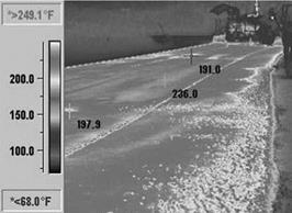
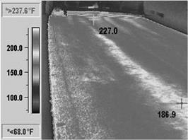
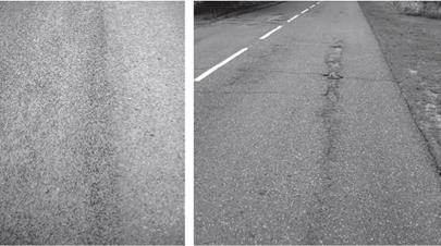
image126Longitudinal porosity parallel to the direction of spreading but not centered behind the paver appears fairly often (Figures 11.22 through 11.24). It may be caused by either of the following:
Longitudinal Porosity behind the Center of the Paver

Longitudinal Porosity behind the Center of the Paver

image128

FIGURE 11.19 Manually corrected edges of a working lane with cooler temperatures and higher porosity.


image129

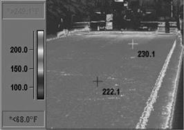
FIGURE 11.20 Position of manually corrected and leveled edges—an infrared image. (Photo courtesy of Kim A. Willoughby, WSDOT, United States.)


image130

FIGURE 11.21 Longitudinal porosity behind the center of the paver.


image131

FIGURE 11.22 Longitudinal porosity off the center of the paver.

image132

FIGURE 11.23 Examples of drop in mixture temperature due to longitudinal porosity in the spread lane. (Photo courtesy of Kim A. Willoughby, WSDOT, United States.)

(a) (b)

image133

FIGURE 11.24 Longitudinal porosity: (a) on a new SMA pavement and (b) pavement dam­age in a porous area. (Photos courtesy of Krzysztof Blazejowski.)

11.8.2.3 Porosity in Other Distinctive Places

Porosity may also be found as follows on an SMA course:

• At the beginning or end of a work site

• In irregularly shaped spots

• At the edge of a compacted course

Porous spots (areas) occur fairly frequently at the beginning or end of a work site when spreading an SMA (or other asphalt mixture) course. This chiefly results from some difficulties with the correct start of laying by a paver (sometimes called take off). Because the beginning of a work site cannot be cut off and removed, such areas of porosity appear mostly at the beginning of a spreading shift (Figure 11.25).

A similar result happens with the manual spreading of mixtures for some length at the beginning of paving followed by compacting with rollers. Manual work can­not equal the efficiency of placement with a paver, which provides more than 80% of the initial compaction. The effect is evident—the course in that area is uncompacted and uneven. Other places that were manually placed because there was no room for a paver look similar (Figure 11.26).

11.8.2.4 spot porosity

As mentioned before, pockets of porosity appear cyclically now and then (Figures 11.27 and 11.28). Their cause is not easy to explain. Maybe the paver was setup incorrectly or, more frequently, perhaps there were pieces of cool mixture in the SMA or segre­gation was still occurring in that stage of mixture production. Or the cause may be something entirely different and difficult to determine.

EPU

Epu is the design I came up with for my house. It features a stain­less steel desk, a tiny fireplace, a refrigerator, sink, stovetop, wet bath, a full-sized bed, plenty of storage and integral wheels. The 89 square feet listed do not in­clude the porch or sleeping loft. It is shown here with an optional Gothic window.

: % ч?

Square feet: 102

House width: 8’

House length: 15’

Road Height: 13’-5”

Dry Weight: 4900 lbs

Porch: 2%’x 2%’

Great Room: 6’ x 6%’ Kitchen: 4’ x 4[2]/2’

Bathroom: 4’x2’

Ceiling height: 6’ 6”

Loft height: 3’ 8”

-sizes are approximate

The Weebee is much like the Epu design with the addition of a Dutch hip roof and a bump-out downstairs. The 102 square feet listed only refer to the downstairs and not the porch or loft. This tiny abode comes on integral wheels. The bump-out fits a table or a couch that folds out into a bed. 1

Square feet: 89

House width: 12’ House length: 9’

Dry Weight: 4700 lbs

Porch: 3’x 1 %’

Great Room: 6’ x 6%’ Kitchen: 4’ x 4[3]/2’

Bathroom: 4’x2’

Ceiling height: 6’ 6”

Loft height: 3’ 8”

-sizes are approximate

Hinge Plate Designs

There are three basic types of hinge designs. One type, illustrated in Fig. 7.30a, develops a hinge by cutting through all but the back flange. The front flange is connected with a slotted plate known as a friction plate. When the post is struck, the friction plate sepa­rates from the slotted bolt holes as the back flange bends. This type of hinge creates a maintenance problem, since the post is destroyed and must be replaced after each impact. It is also more difficult to predict the resistance of the hinge, which is depen­dent upon the post size and depth of cut.

Another type (Fig. 7.30b) utilizes a rear hinge plate. This plate is similar to the fric­tion plate but does not have slotted bolt holes. With this type of hinge, the sign support is completely cut in two pieces, with the hinge plate bolted on the back and the friction plate on the front. When impacted, the friction plate releases through the slotted bolt holes and the hinge plate bends back. Maintenance after impact is simplified, since the hinge plate can be removed and the upper and lower support pieces reused with a new hinge plate. Proper operation of the friction plate design is dependent upon proper bolt size and torque. If the bolts are too small, or not torqued sufficiently, wind loads will cause the friction plate to become loose and the top of the sign to fall back. If the bolts are too large or torqued too much, the support will not separate properly upon impact [45].

The third hinge type (Fig. 7.30c) utilizes a rear hinge plate and a front hinge plate with a weakened section. When impacted, the section fractures through the plane of the holes, thus permitting the back hinge plate to bend. This design has an advantage over the friction-hinge plate design while remaining easy to repair. The advantage is that the torquing requirements on the friction plate are not critical for proper operation. The front hinge plate in Fig. 7.30c is weakened by drilling holes so that only 33 percent of the plate material remains. Figure 7.31 shows commercially available frangible hinge plates available from Transpo Industries. The three hinge systems presented in Fig. 7.30 are unidirectional and should not be used in areas requiring bidirectional performance. Only the Transpo hinge system offers bidirectional performance.

Cabinet Basics

Cabinets today are basically boxes of plywood, particleboard, or medium-density fiberboard (MDF) panels that are glued and screwed together. Side panels, bottoms, and partitions are typically 3/ in. thick; back panels are usually in. thick. Cabinet faces are either frameless (the edges of the panels are the frame, although they may be veneered or edge-banded) or face frame (a four-sided wood frame covers the edges of each box).

Factory-made cabinets are frameless (also called European style). Having fewer elements and a simpler design, they are easier to manufacture. (The cabinets shown in the installation photos are frameless.) Doors and drawers typically lie flush on the case and overlay the panel edges. Usually, there’s % in. between the door and the drawer edges.

Face-frame cabinets are a bit more work, but offer more visual variety. You can expose more or less of the frame, vary the gaps between drawers and doors, use different hinge types, and so on. In general, designers who want a more ornamental, less severe, more traditional look often specify face-frame cabinets.

In addition to the elements above, cabinet cases have nailers (mounting rails) that you screw through to secure the cabinets to the studs. Base cabinets also have stringers— plywood webs across the top—to make boxes more rigid, keep partitions and sides in place, and provide something solid to screw the countertop to.

Kickspaces

The indentation at the bottom of a base cabi­net that provides room for your toes, so you can belly up to the cabinet while prepping food or doing dishes, is called the kickspace. Without a kickspace, you’d need to lean for­ward to work at the counter—a sure recipe for backaches. Custom-made cabinets sit on a separate rough toekick (also called a plinth or sub-base), which is often assembled on site; whereas most (but not all) factory-made base cabinets arrive with toekicks built in. Toekicks are covered by a kickface, or finish toekick, a %-in. plywood strip with the same finish as the cabinets or a vinyl strip; the kickface is better installed after the finish floor.

Scribes

Cabinet assemblies also include small but important filler strips called a scribe pieces. These typically have a rabbeted back so they can be easily be ripped down to fill gaps between cabinets or between a cabinet and a wall. On a frameless cabinet, a separate scribe piece may be attached to a side panel, near its face; whereas on face-frame cabinets, the frame stile (vertical piece) has a rabbeted back edge (for scribing). In addition, many cabinet side panels extend slightly beyond the back panels, so those side panels can be scribed to fit snugly to the wall, as shown in the top left photo on p. 311. Custom cabinet­makers often create a separate scribe panel to dress up the end cabinet in a run and cover any gaps along the wall.

Better-grade cabinets have mounting rails on the outside of back panels so the rails are not visible inside the cabinet case. The edge detail shown in the enlargment is typical. The countertop substrate—here, 3/4 in. plywood-screws to stringers at the top of the cabinet case. Screw the cabinet bottom to the rough toekick.

Подпись:Подпись:image630Подпись: Cabinet-Mounting and Edge DetailsПодпись: Stone countertop the cabinets—and review those measurements and conditions again after the cabinets arrive.
Continuous Porosity by the Edge

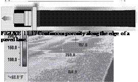
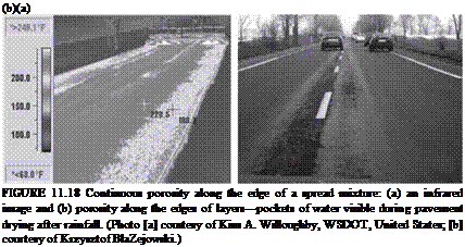
This defect appears in a continuous way along the edge of a layer (Figures 11.17 and 11.18). It is mainly brought about by the following:

image121

FIGuRE 11.13 Formation of streaks or mixture pulling due to incorrect setup of paver screed segments.

image122

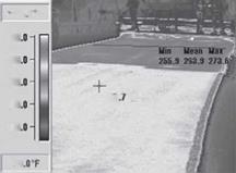
FIGuRE 11.14 The effects of an incorrect paver setup, temperature in degrees Fahrenheit. (Photo courtesy of Kim A. Willoughby, WSDOT, United States.)

image123

FIGuRE 11.15 Area of an uncompacted cool mixture during a paver standstill (a zone of cooling mixture that is inaccessible to rollers).

image124
Подпись: '
Подпись: ill

FIGURE 11.16 Paver standstills and their effects—infrared images. (Photos courtesy of Kim A. Willoughby, WSDOT, United States.)

• Badly adjusted mechanism of mixture distribution through the augers or improper operation of the augers (insufficient quantity of a mixture sup­plied to the screed edge)

• Length of augers too short in comparison with the board width (several board segments with no additional feeding segments applied)

The porosity of a layer is usually easily seen when the surface is wet (Figure 11.18.b). Another problem (less often observed) can be caused by manual raking of a mixture along the edges of a spread lane (Figures 11.19 and 11.20). Unfortunately, leveling a newly spread mixture with rakes or shovels is the customary manner of some paver teams. Manual raking cannot produce the same level of uniformity as mechanical leveling, leading to cooler portions and porous areas in the mat.