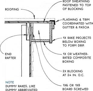
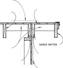
EXPOSED RAKE WITH VERGE RAFTER
NOTE
![]()
![]()


![]()
![]()
![]()
![]()

 cOORDiNATE Flashing & TRiM with gutter AND FASciA.
ExTERiOR-RATED ROOF SHEATHiNG AT ExpOSED pORTiON OF ROOF

NOTE
![]()
![]()


![]()
![]()
![]()
![]()

 cOORDiNATE Flashing & TRiM with gutter AND FASciA.
ExTERiOR-RATED ROOF SHEATHiNG AT ExpOSED pORTiON OF ROOF
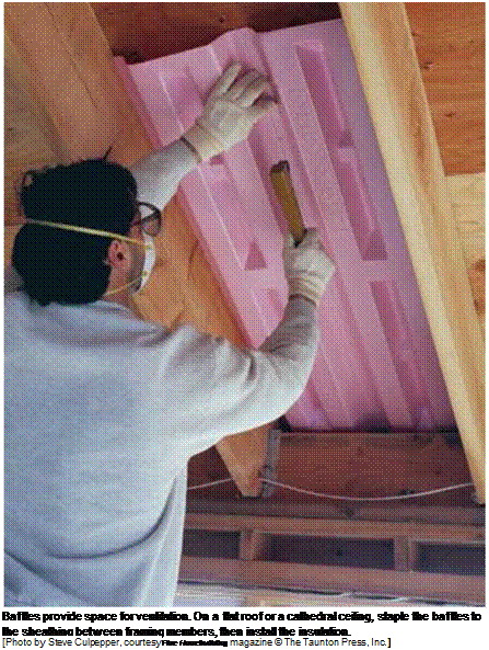
Light, fairly inexpensive, and easy to cut and install, rigid-foam insulation has a lot going for it. This insulation board comes in different thicknesses and sheet sizes. Depending on the manufacturer, it comes in shades of blue, green, and pink. A 1/2-in.-thick sheet is rated at R-3; a 1-in. sheet is rated at R-5.
EXTERIOR USE. Rigid foam is often used on building exteriors. In regions where there is no danger of earthquakes or hurricanes, foam sheets are frequently used in place of wall sheathing.
With this type of installation, sheets of plywood or OSB are still required at the corners of the house and every 25 ft. to provide lateral bracing for the structure; however, foam boards are used between the corner sheets and are nailed directly to the studs (see Chapter 6).Taping the seams between the sheets improves the foam’s performance as a wind barrier.
I like to use foam insulation on the exterior of framed walls, because up to 25 percent of a wall’s area can consist of solid wood— studs, headers, trimmers, and so on. Wood acts as a thermal bridge, allowing heat or cold to be conducted through a wall. Rigid foam helps block this conduction. Sheathing with 4-ft. by 9-ft. foam panels enables you to cover a standard-height wall and the rim joist below it.
Rigid-foam insulation gives you more flexibility in meeting code requirements. Used in conjunction with high-density R-15 fiberglass batts in a 2×4 wall, rigid foam can bring the R-value of a 2×4 wall up to that of a 2×6 wall with standard R-19-rated fiberglass (without the expense of wider framing). Using 2×4 walls, instead of 2x6s, means that your house gains an extra 2 in. all the way around the interior.
There are two important considerations if you’re sheathing a house exterior with foam insulation. First, some types of exterior siding (wood shingles and clapboard, for example) are best installed over solid backing rather than over foam board. Second, if you’re installing rigid foam over plywood or OSB sheathing, make sure the jambs for the doors and windows you order are wide enough for the wall. Standard-width jambs may be too narrow. INSTALLING THE FOAM. Working with rigid foam is simple.
It cuts easily with a utility knife. To nail sheets to the wall, I use either 1 V4-in. roofing nails or nails with plastic heads, which are used to secure felt paper to the roof deck. In windy areas, I like to nail about 12 in. o. c. around the edges and 24 in. o. c. in the field. Make sure you fit the sheets together tightly.

and expect them to do their job. Insulation batts must fit snugly between studs or joists and cannot be jammed in tightly or packed loosely and sloppily with gaps all over the place. Kraft paper-faced batts have tabs, which should be stapled to the face of the studs every 12 in. or so.
Many installers staple insulation tabs to the stud sides of the drywall instead of the face.
This makes it easier to install drywall, but when the paper tabs are stapled to the inside of the studs, a slight gap is left along both sides. Gaps are taboo when you’re installing fiberglass insulation because they reduce the insulating value of the wall, especially on vertical walls.
If you plan to install fiberglass insulation in warm, humid climates (such as the southeastern United States), buy unfaced batts (see the photo on p. 201). Fiberglass insulation with kraft paper facing acts as a vapor barrier on the inside of exterior walls, potentially causing moisture problems.
For partial bays (less than МЬг in. or 22//2 in. wide between studs) and small spaces, such as over headers and under windows, insulation must be cut to fit. Measure the width and length of smaller bays and cut the insulation about Vi in. to 1 in. larger (no more!) in each direction so that it will fit snugly in the cavities (see the sidebar on p. 204). You don’t need to staple smaller pieces of insulation in place; the snug fit should hold them until the drywall is installed.
While you’re insulating, keep in mind that another property of insulation is sound suppression. Given its relatively reasonable cost, you may want to use unfaced insulation in bedroom walls that adjoin a bathroom, living room, or utility room.
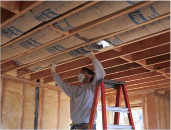
Take even more care when insulating the ceiling (see the photo below). Any heat that escapes into the attic can cause snow to melt, possibly causing an ice dam on your roof. When insulation batts butt together end to end in the ceiling, make sure the joints are tight.
 Because of the importance of keeping heat in the living area and out of the attic, I prefer using blown-in cellulose for the attic, even if the walls are insulated with fiberglass batts. Cellulose settles into and around gaps in the framing, forming what amounts to a giant down comforter over the entire living area of your house. And remember, it doesn’t cost much to add a few more inches of cellulose— say, 14 in. to 18 in. rather than just 12 in.—but it will save on heating and cooling costs for the life of the house.

It’s also easy to determine rafter length with a calculator that has a square-root function. Knowing that a2 + b2 = c2 is the key (this is the Pythagorean theorem, the formula for finding the lengths of the sides of a right triangle). If the roof pitch is 4 (a) in 12 (b), then a2 (16) + b2 (144) = 160; the square root of 160 is 12.65. The length of the rafter (hypotenuse) for a 4-in-12 pitch roof with 1 ft. of run is 12.65 in. (see the drawing on p. 144). If the rafter runs 7 ft., for example, multiply 12.65 by 7 to get 88.55 in., or 7.379 ft. Converting the decimal to fractions gives you a rafter length of 7 ft. 414 in.
Laying out and cutting rafters
To determine the number, length (including enough for the rafter tail), and size of the rafters, you’ll need to check the plans. If the rafters are spaced 16 in. o. c., divide the length of the building by four, multiply this figure by three, and add one more. Double the result to cover both sides of the roof.
If the rafters are spaced 24 in. o. c., the process is even easier. Just take the length of the building and add two.
These days, rafters tend to be made from 2x8s or larger so that they can be filled with adequate insulation to meet energy codes and to support heavy roof tiles or snow loads. Many of the roofs I cut and stacked years ago were made from 2x4s and 2x6s. Recently, I got a call from a family who lived in such a house. One night they heard a horrible sound above, like something breaking, and asked if I would please have a look-see.
I crawled up in the attic, and they were right: Two rafters were split, and others were sagging. They had changed the roof covering from composition shingles to concrete tiles without adding extra supports to the rafters. Wet snow loads can cause the same damage.
Many buildings also have barge rafters (two on each end), that form the overhang on the gable ends. These rafters

are trim pieces that hang away from the building and are clearly visible to anyone who looks up. As you go through the rafter stock, lay aside four clean, straight pieces so that your trim will look good. But check the plans. Barge rafters may be smaller than the regular rafters or made from cedar, redwood, spruce, or pine.
One of the fascinating aspects of building a roof is that all the rafters can be laid out and cut on the ground. Then, as perfect as a picture puzzle, the parts fit together on the house frame to form the roof. It seems rather magical, but it’s not difficult to do. Start at the beginning, by laying out a pair of common rafters on your sawhorses. First, though, make a rafter template out of scrap 1x or plywood that is the same width as your rafter stock (see the sidebar on the facing page), so that you won’t continually have to use your small rafter square to lay out the rafters. I use this template
to scribe the ridge cut (a plumb cut on the rafter stock that fits against the ridge board) and the bird’s mouth (the notch in the rafter that rests on the top wall plate).
To use the template, place it on rafter stock near one end and mark the plumb cut. Make sure the crown side is up. From the long point of this mark, measure along the top of the stock and mark the length of the rafter. Then align the template’s registration mark with the rafter-length mark and scribe the bird’s mouth. That’s all there is to it. Be sure you have enough stock left over for the tail forming the overhang.
With the first rafter marked to length, make the ridge cut with your circular saw. Move to the other end of the stock and make the cuts for the bird’s mouth, overcutting just enough to remove the wedge. Use this rafter as a pattern to lay out and cut the second rafter.
Use a small rafter square to scribe the ridge plumb cut at one end of the 1×6 template, as shown in the drawing at right. Move down the template about 1 ft. and scribe the heel cut (a plumb cut) of the bird’s mouth. Extend this line across the top edge of the template. This will serve as your registration or guide mark when laying out the bird’s mouth on the rafter stock. Then mark the level seat cut on the bottom edge of the template, which will be 31/2 in. long for 2×4 walls and 51/г in. long for 2×6 walls.
Add a 1×2 fence, and the template is ready for use (see the drawing below).
![]()


![]()
![]()
 There is no need to lay out and cut rafter tails at this point. Instead, let the tails run long. Once the roof is built, a chalkline will be snapped across the rafters hanging outside the walls. The tails can then be cut in place, ready for fascia to be nailed to them.

 Before cutting up all the expensive rafter stock, it’s a simple matter to check to see that these first two rafters are cut properly. With a partner, pull up the two rafters, one on each side of the building. Hold them in place with the seat cuts snug at the plate lines. Place a short 2x ridge between the rafters at the peak, then check to see if all the cuts—both at the bird’s mouth and at the ridge board—fit perfectly. When you are satisfied, use the first rafter as a pattern to lay out and cut the remaining rafters. Once the rafters are cut, carry them to the house and lean them against a wall, ridge end up. Rafter tails will be cut to length once the roof is built.
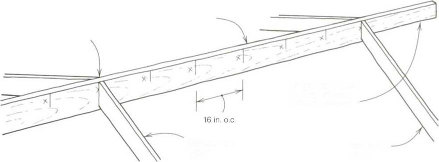
Like truss roofs, stick-built roofs have frieze blocks nailed between each rafter at the plate line that help stabilize the rafters. Cut the blocks slightly less than 141/2 in. long for rafters at 16 in. o. c. and slightly less than 221/г in. long for those nailed 24 in. o. c. If blocks are set on the wall, they may have to be cut 1 Vi in. shorter (13 in.) because of the ceiling joist nailed to the plate.
Laying out and installing the ridge board
Before tackling the ridge board and installing the rafters, take the time to build yourself a safe place to work. Nail plywood strips left over from the floor sheathing on top of the ceiling joists under the ridge line to make a catwalk that’s at least 2 ft. wide and that runs the full length of the building. There are times, especially when you have a high ridge or are working on a house without ceiling joists, that you will have to set up a scaffold. It’s best to use a solidly built metal scaffold (you can rent these) to guarantee your safety. Anytime you work high up, be safe. Risks are for trained Hollywood stunt men.
A secure catwalk gives you a place to lay out the ridge boards, which need to be as straight as possible. The ridge board must be wider than the rafter stock so that the angled plumb cut of the rafter bears fully across the face of the ridge board. So if the rafters are 2×6, use a 2×8 for the ridge board. Begin the ridge – board layout at one end, marking it
Fat spots in wheel paths appear at the time of SMA pavement trafficking. They are located in the paths of vehicle wheels and can run up to several hundred meters (possibly including the whole SMA wearing course of a road) (Figure 11.34).
We have to go back to the chapter on designing an SMA mixture and the volume relations taking place in it to explain causes of the appearance of such “sweating offs” of mastic in the wheel paths. Recall that some air voids for mastic are intentionally left in a compacted and interlocked coarse aggregate skeleton. Additional compaction of a course under tires causes a closer arrangement of the coarse aggregate grains during trafficking. This reduces the volume of free space designed for mastic, and consequently the mastic is squeezed-out onto the surface. In some cases, this phenomenon confirms the Dutch idea about the enlarging effect and the need to design SMA with a bit higher void content (see Chapter 7).
Another reason for the occurrence of such a phenomenon is opening the pavement to traffic too early. Loads on an SMA that is still warm can destroy this mixture in a short time.
With the correct orientation and southfacing windows, your house can have great light and heat in winter—but it also can have the potential for overheating if you don’t balance the amount of windows in the house with the amount of mass. Thermal mass comes from materials that absorb heat, such as concrete, tile, brick and concrete
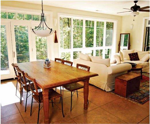 Floor mass. The floor is the easiest place to add thermal mass, which regulates temperatures all year long. This colored concrete floor is covered with a soy-based sealer and runs throughout the first level of the house. During the day, it absorbs excess heat from the south-facing windows, releasing it at night.
block, and water. However, water requires diligence to prevent algae and mold, and it is harder to incorporate into the structure of a house. The easiest mass to build into a house is some form of masonry.
Generally, the more south-facing windows there are, the more mass a house needs to balance the heat gain indoors and keep it cool. When sun shines through the windows, it strikes interior surfaces. Sunlight can either radiate into the air, heating the house, or be absorbed by the material it strikes. If it is absorbed, you get light in the house but not heat. Because heat moves from hot to cold, the mass material will continue to absorb heat as long as it remains colder than the surrounding air.
The right amount of thermal mass draws heat out of the air during the day, and radiates the heat to warm the home in the evening when the air temperature drops, making mechanical heating less necessary. In the morning, when the atmosphere heats up
once more, the cooled mass material starts to absorb the day’s heat all over again.
The easiest way to add mass to a house is on the floor. A significant amount is needed: In a typical passive-solar home, the concrete, tile, or brick floor should be 4 in. thick. Tile installed on cementboard on a subfloor is not enough.
Trombe walls are another design option. They are interior masonry walls behind south-facing windows with a narrow airspace between them. When the sun comes in, the heat is trapped in the airspace and then is absorbed by the wall. It acts as a heat sink for the house and can radiate the heat inside.
If you’re planning a new house, you also can build mass into the walls. Precast concrete panels or AAC blocks introduce a significant amount of mass. These walls can be finished in a variety of ways; stucco is the simplest and most low-maintenance option, but you can attach siding if you prefer.
On the inside, concrete panels are typically painted, while the AAC can be finished with stucco or drywall. Finished this way, the interiors look like any other house, except for the added aesthetic of deep windowsills.
Thermal mass has an added benefit: Not only does it absorb heat, but it’s also cool to the touch, which cools you. You can keep the air temperature of your home several degrees higher in the summer if you’re walking on a cool floor. One way heat is transferred is through conduction—the movement of heat from one object to another through direct contact. You touch the floor, and because you are warmer than the floor, the heat in you (the warmer object) moves to the floor (the cooler object). You feel cooler, no mechanical means required.
Massing is the hardest strategy to add to an existing home. If the house was not designed to accommodate a 4-in.-thick masonry or concrete floor, it’s not easy to add one. If you are adding to the south side of your house, however, you can consider a slab floor, a masonry wall, or a masonry fireplace.
The importance sampling technique concentrates the distribution of sampling points in the part of the domain that is most “important” for the task rather than spreading them out evenly (Marshall, 1956). Refer to the problem of evaluating an integral in Eq. (6.49) by the sample-mean method. The importance sampling technique attempts to generate M sampling points to reduce the variance of G given by Eq. (6.61).
Rubinstein (1981) showed that the PDF fx(x) that minimizes Eq. (6.61) can be obtained as
|
|||
|
|
||
|
|||
|
|||
|
|||
|
|||
 |
|||
 |
|||
|
|||
|
From condition (i), the coefficient b can be obtained easily as b = 0.00001. Substituting b = 0.00001 into ht(t), one can verify that condition (ii) is also satisfied. Therefore, ht(t) = 0.006 — 0.00001 x t is a legitimate PDF in 0 < t < 200. To generate random variates from ht(t), the CDF-inverse method can be used because the CDF of ht(t) can be obtained easily as
Ht(T) = U = (0.006 — 0.00001t) dt = 0.006T — ^°-002001) T 2
Solving for T in terms of U, one obtains
in which a = 0.006 and b = 0.00001. Based on the boundary conditions of a CDF, that is, Ht(t = 0) = 0 and Ht(t = 200) = 1, the only valid expression for T from ht(t) is
T 2a — V 4a2 — 8bU
= 2b
Hence the preceding equation can be used to generate random variates from ht(t). The algorithm for this example can be outlined as follows:
1. Generate n standard uniform random variates ui from U(0, 1).
2. Compute ti according to Eq. (6.73), yielding n random variates from ht(t) = 0.006 —
0. 00001t, 0 < t < 200.
3. Estimate the pump failure probability as
|
|
|
|
|
|
|
|

![]()
4. To assess the error associated with the estimated pump failure probability by the preceding equation, compute the following quantity:
 |
|
|
|
|
|
|
|

Using this algorithm, the estimated pump failure probability is pf = 0.14767, whereas the exact failure probability is 0.147856. The associated standard error can be computed as
sp f = 0.00023
Assuming normality for the estimated pump failure probability, the 95 percent confidence interval containing the exact risk pf is
pf ± 1.96spf = (0.14722,0.14813)
Comparing the solutions with those of Examples 6.6 and 6.7, it is observed that with the same n = 2000, the importance sampling method has a 0.126 percent error. The magnitude of error and the accuracy level are somewhat worse than the sample- mean procedure but are still far better than the hit-and-miss algorithm. The accuracy of the importance sampling technique depends on how ht(t) is specified. As can be observed from Problem 6.29, use of the exponential function for ft(t) improves the accuracy tremendously.
As I mentioned in section 2, passive cooling involves being able to control the airflow and heat moving through a house. This means stopping unwanted air infiltration by creating a tight building envelope. You can tighten up the house with good insulation, caulking all penetrations and sealing around windows and doors. Weatherstripping exterior doors and installing double-paned, argon-filled windows with low-e coatings can help as well. Put a tight-fitting damper in the chimney and a properly insulated cover over any attic access. Making your home’s envelope tight enables you to let air
|
|
in and out when you choose and to close up the house when you want.
If you can, use more insulation than local codes require, and add the sealing package that many insulators offer. Spray-foam insulation provides a high R-value in a small amount of space and can double as an air seal. That’s particularly important here in the Southeast, where moisture in the air can lead to mold, poor indoor-air quality, and even structural damage.
If you’re building a new house, look into building systems that offer insulation values that are at least double what standard stick – built structures offer. In addition to precast concrete panels and AAC (aerated autoclaved concrete) block, you might consider agriboard panels. Made of compressed wheat straw sandwiched between oriented strand board (OSB), these 8-in.-thick panels offer an R-value of 25.4 versus the R-13 or R-15 of a standard 2×4 fiberglass-filled wall.
Transpo Industries manufactures a series of breakaway systems for ground-mounted sign supports, marketed under the trade name Break-Safe. The Break-Safe system uses frangible couplers and is available for U-channel, both concrete footing and direct burial; 3-in to 4.5-in (75-mm to 115-mm) round pipe; 3-in to 5-in (75-mm to 127-mm) square
|
FIGURE 7.46 Weakened wooden post for multiple supports. |
|
FIGURE 7.47 Transpo Break-Safe system for back-to-back U-channel supports. (a) Concrete footing. (b) Direct burial. |
tube; and wide-flange and standard beam shapes. Schematics of Transpo Industries concrete base and the direct burial system for back-to-back U-channel are presented in Fig. 7.47. Figure 7.48 shows the Break-Safe system for square-tube and round-pipe supports [33].
The Break-Safe has a number of advantages over slip base designs. One advantage is that the critical torque requirements of the slip base bolts are eliminated by the use
|
FIGURE 7.48 Transpo Break-Safe system for square-tube and round-pipe supports. (a) Square-tube support. (b) Round-pipe support. |
|
FIGURE 7.49 Concrete footing and installation jig for Break-Safe installations. (a) Plan view of footing. (b) Installation jig. |
of frangible couplings. There are retrofit kits available, for wide-flange and standard beam supports, that use the existing slip base anchor to convert to a frangible coupler design. Another advantage of the Break-Safe system is that the concrete base installations do not require a protruding stub. This decreases the probability of snagging the undercarriage of an impacting vehicle, and damage to the anchor system itself. The protruding stub is eliminated by bolting the frangible coupling into anchors placed in the concrete footing. Proper assembly requires that the anchors be accurately placed for each type of support system. Accurate anchor placement requires the use of an installation jig similar to Fig. 7.49 [33]. The anchor spacings, dimensions A and B in Fig. 7.49b, vary with the type and size of sign support being installed. Frangible and load concentration couplers (Fig. 7.22) usually perform satisfactorily when struck from any direction (they are multidirectional).
Examples of variation of resilient modulus and permanent deformations of subgrade soils with moisture content are presented in Figs. 10.15 and 10.16. Figure 10.15 presents results obtained on a clayey sand (14% fines, optimum moisture content
wOPM = 8%).
Figure 10.16 presents results obtained for a silt (85% fines, optimum moisture content wOPM = 14%). For the 2 soils, the resilient modulus (determined for two different levels of stress) decreases by a factor of 3-4 when the water content increases from wOPM — 2% to wOPM + 2% (typical in-situ moisture contents). For the same change, the permanent axial strains (determined after 200 000 load cycles with cyclic stresses p = 26 kPa and q = 80 kPa) increase considerably.
Brull (1983) performed triaxial tests on 2 different soils, a loam (from Sterrebeek in Belgium) and a slightly clayey sand (from Noucelles in Belgium). The tests were carried out for different dry volumetric masses, for suctions between 0 and 600 kPa, for different confining pressures (between 10 and 50 kPa) and for different deviatoric stress (between 5 and 25 kPa). The soil water characteristic curves (also known as retention curves) as a function of the volumetric mass of the samples are presented in Fig. 10.17.
The Resilient Modulus, Mr, of the different samples were determined from the triaxial tests. The influence of the volumetric mass and stresses have been analysed. For the tested materials, Brull attempted to establish a linear correlation between the Resilient Modulus, Mr, and the suction, s (Fig. 10.18).
a.
Cui (1993) tested a remoulded Jossigny silt in an unsaturated state and gave an evaluation of Resilient Modulus, Mr, and shear modulus, Gr, as a function of confining pressure and of suction level (Fig. 10.19).
Multimount sign supports have two or more support posts of breakaway design. The breakaway mechanism is either a fracture or a slip base type. Fracture mechanisms consist of frangible couplers or frangible one-piece posts.
7.8.1 One-Piece Multiple-Mount Sign Supports
Direct burial assemblies that are approved for use include dual 3-lb/ft (4.5-kg/m) U-channel and dual 4-in X 4-in (90-mm X 90-mm) wooden posts that have been modified with two 1.5-in (38-mm) holes placed at 4 and 18 in (100 and 450 mm) above the ground line. Other than these exceptions, multiple-mount sign supports require the use of anchor pieces, sleeves, slip bases, or frangible couplings for acceptable impact performance. Only those devices approved for use by the FHWA should be used for multiple-mount supports. Since more than one support can be simultaneously struck by an errant vehicle, it is important that proper installation procedures be followed. Figure 7.46 illustrates the holes drilled in a direct burial wooden post to provide the weakened cross-section required for multiple wooden post installation.