Guidelines for Fastening Sign Panels to Single-Support Systems

The following guidelines should be followed for fastening sign panels to supports:

• Bolts smaller than %s in (8 mm) should not be used to fasten sign panels to the support. The bolts must be long enough to provide for bolt extension beyond the fastening nut.

• Carriage bolts, or hex bolts with washers between the hex head and sign face, should be used to reduce the possibility that the sign might separate from the support upon impact. Flat washers and lock washers should be used at the nut end of the bolt.

• The bolts must be tightened sufficiently to prevent loosening, but not so tight as to distort the sign face.

LOCK WASHER HEX NUT

RECTANQULAR HEAD BOLT

Let the House Breathe a Bit

When mechanical systems are sized for a home, they’re often designed with the mind-set that the house is never open to the elements. I find this is rarely true; in fact, most of my clients very much want to connect their home’s indoor and outdoor spaces. Doesn’t it make more sense, then, to

I Overhangs

design houses to work in partnership with their environment rather than to function with no regard for it?

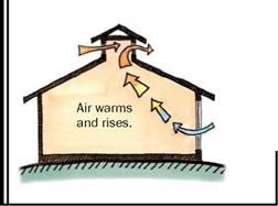
To understand best what ventilation can do for your home, you need to remember two simple principles: One is that heat al­ways moves from hot areas to cold areas, and the other is that warm air rises.

If you are designing a new house, spend some time on the site, learn where the breezes come from, and use that informa­tion when locating the windows on your house. Use casements that swing open to help catch breezes. Having different units open in different directions allows you to take advantage of winds coming from mul­tiple directions.

A studied approach.

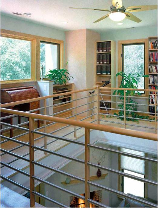
Designing this second – floor library as an open balcony permits warm air to rise unimpeded up and out the second- floor windows. ceiling fans assist the natural airflow.


Let the House Breathe a Bit

Подпись: Chimney EffectПодпись: Hot air exits; cross ventilation accelerates air movement.Подпись: Cooler air Let the House Breathe a BitThe simplest form of smart ventilation is cross ventilation. When you open a window in your home, you can let in a slight breeze, but when you then open a window on the opposite side of the room, the strength of that through-breeze increases significantly. If the entry window is small and the window through which the breeze exits is large, it increases in speed. A cool breeze in the eve­ning when the sun is going down absorbs the heat in your house (heat moving from hot to cold); as the air heats up, it rises. So the best way to let hot air out of your house

is to have a large opening up high. The greater the distance between the intake and the output, the better.

This air movement is called the chimney effect (see the drawing on the facing page). I use it in my three-story home. When a cool breeze comes at the end of the day, I open the windows downstairs and the French doors on the third floor and wash out the entire house in minutes. The effect is height­ened by an open plan, a small footprint, and a staircase in the middle that makes the whole house very much like a chimney.

Vaulted ceilings and high windows in a clerestory or cupola also promote the chim­ney effect. The sloped ceiling encourages air to move to the top of the cupola, and operable windows on both sides allow cross ventilation.

If you live in a dry climate, you can boost your home’s ventilation cooling with water cooling. Dry air moving over water absorbs moisture and subsequently drops in tem­perature. (This is how evaporative coolers work.) Placing windows near a pond or an­other water feature lets you capture the cool air as it comes off the water and into the house. You get free air-conditioning along with the soothing bonus of a water view.

FASTENING SIGN BLANKS ON SINGLE-SIGN-SUPPORT SYSTEMS

Regardless of the type of support that is being used, there are three general rules that must be followed: (1) the top of the sign should be 9 ft (2750 mm) above ground level to reduce the possibility of intrusion into the passenger compartment upon impact, (2) the retaining bolts must be snug but not so tight as to distort the sign face, and (3) the bolts must be of the proper size and length to prevent the sign blank from separating from the support.

FIGURE 7.37 Improper installation of slip base anchor piece.

Fastening to a U-Channel. Signs are normally mounted on the front face of the U-channel. This is the widest face of the U-channel. Signs can also be mounted on the narrow face, as in back-to-back sign installations, for example, but the decreased surface contact with the sign can result in damage to the sign face due to environ­mental loads. Side mounting on a U-channel requires channel brackets, and brackets for mounting street name signs to the top of the post are available. Typical sign blank installations for a U-channel are presented in Fig. 7.38.

Fastening to Wood Supports. Sign installation on wood supports requires a bolt completely through the post and fastened with a nut. Lag bolts are not recommended for fastening sign blanks to the posts. Fastening with lag bolts is unpredictable upon impact because of the size of the bore hole, possible postsplitting, the presence of knots, and variable characteristics of the wood.

Fastening to Square Tubes. Sign installations on square tubes can be accomplished by %s-in (8-mm) bolts and nuts or by the use of rivets. Figure 7.39 presents typical sign panel fastening details for shaped wooden and square-tube sign supports.

Fastening to Round Steel Shapes. Signs should not be fastened directly to standard steel pipe or to light standards. The contact area between the back of the sign and the support due to the round support shape is too small to withstand the wind and other environmental loads. A number of different fastening methods can be used, including B-clamps, U-bolts, and stainless steel band clamps. Figure 7.40 presents the configura­tion of the B and stainless steel band clamps. The dimensions shown for the B-clamp are typical and vary slightly by manufacturer. The B-clamp is also available in other sizes than shown in Fig. 7.40.

FLAT WASHER

ND LOCK WASHER

50 MIN

FIGURE 7.38 Typical sign blank fastening to U-channel. Dimensions shown as mm: 50 mm = 1 in.

FIGURE 7.40 Typical design of B and stainless band clamps for round sign supports. (a) B-type clamp. (b) Stainless steel band clamps for round sign supports. Dimensions shown as mm. Conversions: 8 mm = % in, 9 mm = /8 in, 50 mm = 2 in, 100 mm = 4 in, 125 mm = 5 in.

U-bolts can also be used to fasten signs to round supports. The U-bolt is attached to the sign by the use of Z-bar aluminum channel or pieces of U-channel. The U-bolt is purchased with an anchor chair to grip the post. Fastening details for U-bolts with aluminum Z-bar are presented in Fig. 7.41 and with aluminum channel or U-channel in Fig. 7.42.

Fastening to Structural Steel Shapes. Fastening signs to S – or W-shaped beam posts, often used with slip base designs, should be accomplished by using a stiffener. Clamps are used to fasten the stiffeners to the support, eliminating the need to drill into the support itself. Fastening details using aluminum Z-bar as the stiffener are presented in

FIGURE 7.41 Fastening details for aluminum Z-bar and channel. (a) Z-bar. (b) Aluminum channel. Dimensions shown as mm. Conversions: 8 mm = ife in, 205 mm = 8 in, 355 mm = 14 in, 460 mm = 18 in, 760 mm = /0 in.

FIGURE 7.42 Typical variations for installing signs on round posts. (a) With formed channel. (b) With clamps or bolts.

FIGURE 7.43 Aluminum Z-bar for attaching sign panels to beam post. (a) Top view. (b) Side view. Dimensions shown as mm. Conversions: 8 mm = %5 in, 10 mm = % in, 20 mm = %in, 153 mm = 6 in.

Fig. 7.43. Figures 7.44 and 7.45 present fastening details for commercially available

aluminum stiffeners specifically designed for mounting signs to beam supports.

Slip Base Designs

Slip base designs for single sign supports provide the opportunity to use stronger sign supports than would be possible without the slip base design. The purpose of the slip base is to provide a separation plane between the sign support and the anchor system. The two pieces are fastened together with bolts that must be properly tightened, or

Post type and diameter

Embedment type and depth

Comments

Standard (schedule 40) steel pipe Less than 2 in

Direct burial to at least 42

An earth plate measuring 4 in X

(51 mm) ID

in (1070 mm)

12 in X 0.25 in (100 mm X

Equal to or less than

Commercial anchor system

300 mm X 6 mm) must be bolted or welded to the buried end to prevent rotation. Follow manufacturer’s

2 in (51 mm) ID

such as Poz-Loc

instructions.

Equal to or greater

Breakaway design with

The concrete base is 30 in (760 mm)

than 2 in (51 mm) ID

concrete anchor base

deep by 12 in (300 mm)

Round steel tube

Commercial anchor system

diameter. The anchor piece is embedded 24 in (610 mm) in the concrete base. Use an anchor piece one size larger than the anchor post and a reducing coupling for the breakaway action. Top of coupling should not be more than 4 in (100 mm) above ground level.

Follow manufacturer’s

2.5 in (65 mm)

such as Poz-Loc

instructions.

O. D. or less with 12 gauge walls

torqued. If the bolts are not torqued enough, they will be loosened by vibration from environmental loads, causing the sign assembly to separate. If the bolts are torqued too much, the friction between the base of the signpost and the anchor piece will be too large to permit proper separation upon impact. A 20 to 28 gauge metal “keeper plate” should be inserted between the faces of the top and bottom slip bases to prevent the bolts from migrating out of the assembly (Art. 7.4).

There are three basic types of slip base designs for single sign supports. The hori­zontal slip base design (Fig. 7.25) will operate correctly when impacted from either the front or the back. Horizontal slip base designs do not provide the lift capability available from inclined or multidirectional designs. Horizontal slip bases when used as single sign supports therefore do not function as well upon impact as the other slip base designs.

The inclined slip base (Fig. 7.18) is the recommended type of slip base for single sign supports when impact can be expected from only one direction. Its performance upon impact is designed to cause the upper sign support and sign panel to raise up, thus allowing the vehicle to pass completely under the support assembly. The anchor piece of the inclined slip base must be installed so that approaching vehicles encounter the lower edge before the high edge.

The multidirectional slip base is fastened together with three bolts and has a lift cone fastened to the bottom plate. The sign support is tubular with a maximum size of 5 in (127 mm) diameter.

All of the slip base designs require a firm foundation for proper operation. Concrete foundations should be used for all slip bases, since direct burial may result

TABLE 7.11 Slip Base Anchor Piece Installation Requirements for Round Signposts

a. Requirements in U. S. Customary units

Internal

diameter,

Anchor piece

Concrete foundation

ft

stub length, ft

dimensions, ft

2.0

3

3.5 deep X 1.0 diameter

2.5

3

3.5 deep X 1.0 diameter

3.5

4

4.5 deep X 1.0 diameter

4.0

5

5.5 deep X 1.5 diameter

b. Requirements

in SI units

Internal

diameter,

Anchor piece

Concrete foundation

mm

stub length, mm

dimensions, mm

50

920

1066 deep X 300 diameter

64

920

1066 deep X 300 diameter

90

1200

1400 deep X 300 diameter

100

1500

1700 deep X 460 diameter

in base movement and improper release of the slip base. To prevent snagging of the vehicle undercarriage, no part of the anchor piece and its attached slip base may extend more than 4 in (100 mm) above ground level. Horizontal and inclined slip base designs can be constructed with wide-flange, standard-shape, and round sign supports. The concrete footing sizes for wide-flange and standard-shape signposts should be constructed to state specifications. The concrete foundation and anchor stub sizes listed in Table 7.11 are appropriate for round signposts with slip base designs.

Torque Requirements. Specifications for bolt tightness must be followed so that the sign assembly (1) remains intact under normal environmental loadings and (2) separates correctly upon impact. The specifications can be given in a number of ways, such as residual tension, clamping force, or torque. Torque refers to the amount of force used in tightening the nut to the bolt. The result of the nut-to-bolt tightening places the bolt in tension and exerts the clamping force. Measuring the torque is the most convenient method of obtaining a specified tightness. Providing a specified torque, however, does not guarantee a certain clamping force. Irregularities in the threads, heavy coating deposits on galvanized parts, or irregularities on the mating surfaces of the nut and plate faces result in friction forces. These friction forces cause an increase in torque to move the nut without a resulting increase in clamping pressure. To help ensure that the torque speci­fication provides the required clamping force, the nut should be tested for thread irregu­larities by being threaded on the bolt by hand. Also, the proper size flat washers should be used beneath the nut and the head of the bolt. The proper size bolts and recommended torque requirements are provided in Tables 7.12 and 7.13. The tables show requirements for round sign supports by diameter and for other support shapes by unit weight or mass. In U. S. Customary units, S6 X 12.5 designates a standard shape with a depth of 6 in and a unit weight of 12.5 lb/ft; in SI units, S150 X 18.6 member is a standard shape with a depth of 150 mm and a mass of 18.6 kg/m.

Slip Base Orientation. The proper operation of slip bases is also dependent upon proper assembly and correct orientation to the expected direction of impact. The parts,

TABLE 7.12 Connection Requirements for Horizontal and Inclined Slip Bases

a. Requirements in U. S. Customary units

Support shape

Number

Bolt

Required

and size

of bolts

diameter, in

torque, ft-lb

Round, by internal diameter, in

2.0

4

1/2

8 to 12

2.5

4

1/2

8 to 12

3.0

4

1/2

8 to 12

4.0

4

1/2

8 to 12

4.5

4

5/8

19 to 29

Shapes, by lb/ft

0-3.6

4

5/8

7 to 11

3.7-9.0

4

5/8

17 to 26

9.1-13.6

4

3/4

29 to 43

>13.6

4

1

44 to 55

b. Requirements in SI units

Support shape

Number

Bolt

Required

and size

of bolts

diameter, mm

torque, N-m

Round, by internal diameter, mm

50

4

13

11 to 16

64

4

13

11 to 16

75

4

13

11 to 16

100

4

13

11 to 16

125

4

16

26 to 39

Shapes, by kg/m

0-5.4

4

14

10 to 15

5.5-13.4

4

16

23 to 35

13.5-20.2

4

20

40 to 58

>20.2

4

25

60 to 75

TABLE 7.13 Connection Requirements for Multidirectional Slip Bases

a. Requirements in U. S. Customary units

Round support

Number

Bolt

Required

diameter, mm

of bolts

diameter, ft

torque, ft-lb

3.0

3

5/8

19 to 29

3.5

3

5/8

19 to 29

4.0

3

3/4

31 to 46

4.5

3

3/4

31 to 46

b. Requirements in SI units

Round support

Number

Bolt

Required

diameter, mm

of bolts

diameter, mm

torque, N – m

75

3

16

26 to 39

90

3

16

26 to 39

100

3

19

42 to 63

125

3

19

42 to 63

and orientation to the primary direction of travel, for the three types of slip bases are presented in Figs. 7.19, 7.20, and 7.26. The horizontal slip base is generally not used for single sign supports. Where impact from more than one direction is expected, the multidirectional slip base provides better performance because of its design for lift upon impact.

Guidelines for Slip Base Installation. The following guidelines should be followed for slip base installation:

• Slip base installations require a firm foundation to operate properly upon impact. Slip base installations should always include a concrete base and never be directly buried or drilled and backfilled.

• Use proper size bolts for the slip base fastening. Bolts that are too small may not be able to be sufficiently tightened and may fail under environmental loads. Bolts that are too large may become stuck in the release slots upon impact and prevent proper separation.

• Use proper size and strength washers. The washers beneath the nut and head sur­faces should be sufficiently strong to withstand the torque requirements without deforming into the release slots of the base.

• Three washers should be used on each bolt—one each beneath the nut and bolt head, and one between the upper and lower faces of the slip base. The purpose of the washer between the two slip faces is to prevent binding upon impact. All galva­nizing runs or beads should be removed from both the upper and lower faces in the washer areas.

• The nut should be run by hand down the bolt to find thread irregularities that will provide inaccurate torque readings.

• Torque each base bolt to the required specifications.

• Remember that the top portion of the slip base must be attached to the anchor piece. Therefore it is recommended that the anchor piece be installed so that its highest portion extends no more than 3.5 in (90 mm) above the ground. This will help ensure that the addition of the top plate will not result in a height that can snag the undercarriage of an impacting vehicle. The installation shown in Fig. 7.37 is improper and can snag the undercarriage of an impacting vehicle.

• The bolts must be sufficiently long that they can extend approximately % in (10 mm) beyond the nut after complete assembly.

• Do not install an inclined slip base where impact from more than one direction is expected.

Variance-Reduction Techniques

Since Monte Carlo simulation is a sampling procedure, results obtained from the procedure inevitably involve sampling errors, which decrease as the sam­ple size increases. Increasing the sample size to achieve a higher precision generally means an increase in computer time for generating random vari­ates and data processing. Variance-reduction techniques aim at obtaining high accuracy for the Monte Carlo simulation results without having to substan­tially increase the sample size. Hence variance-reduction techniques enhance the statistical efficiency of the Monte Carlo simulation. When applied properly, variance-reduction techniques sometimes can make the difference between an impossible, expensive, simulation study and a feasible, useful one.

Variance-reduction techniques attempt to reduce the error associated with the Monte Carlo simulation results by using known information about the prob­lem at hand. Naturally, such an objective cannot be attained if the analyst is completely ignorant about the problem. On the other extreme, the error is zero if the analyst has complete knowledge about the problem. Rubinstein (1981) stated that “variance reduction cannot be obtained from nothing; it is merely a way of not wasting information.” Therefore, for a problem that is not known at the initial stage of the study, pilot simulations can be performed for the purpose of gaining useful insight into the problem. The insight, then, can be incorporated later into the variance-reduction techniques for a more efficient

simulation study. Therefore, most of the variance-reduction techniques require additional effort on the part of analysts.

LUSBY

The Lusby has a full bathroom, a kichen (sink, stovetop, refrig­erator), a fireplace, two closets, ample shelving, a downstairs bed­room and two lofts for additional sleeping and/or storage. The great room has a high, cathedral ceiling. In addition to the 117 square feet listed, this house contains more than 60 square feet in the lofts.

" u

Square feet: 117

House width: 8’

House length: 19’

Road Height: 13’-5”

Dry Weight: 5400 lbs

Porch: 3’x 7%’

Great Room: 6’ x 6%’ Kitchen: 3[4]/2’ x 61/2’

Bathroom: 3’x 6’

Ceiling height: 6’ 6710’ 6” Loft height: 3’ 8”

-sizes are approximate

POST-FORMING A COUNTERTOP

image653

2. Plastic laminate can be brittle when it’s cold, so the assembly is next moved to a bench with a heated edge. Inverted, the countertop is clamped to the bench and the backsplash is pulled to its final position—at a right angle to the countertop.


image654

3. The ’/i-in. spacers placed earlier are removed, and coved strips along the joint between the countertop and backsplash are hot-glued. Coved strips keep the top and back pieces in place and, because the cove has the same arc as the laminate, they support it as well.


image652

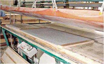
1. At a custom-counter shop, the post-forming machine is a vacuum press that applies heat and pressure to wrap the laminate to the shaped edges of the countertop and splashboard. Note: The substrate is still in two pieces, so when moving the assembly, both pieces must be supported.


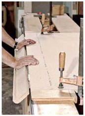
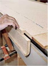
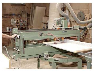
4. Cutting is done by a $100,000 table saw with a diamond blade large enough to cut a razor-clean miter through both the countertop and the backsplash, in one pass.


image655

and, to a degree, stain-proofs them, too. Miracle Sealant’s 511 Porous Plus, a penetrating sealer, is effective at stain-proofing cementitious materials from grout to concrete. One of the best books on casting your own countertop is Fu-Tung Cheng’s Concrete Countertops (The Taunton Press).

Wood is a sentimental favorite because it’s warm and beautiful, but it must be correctly finished and carefully sealed to prevent damage around sinks or along seams where water could collect. There are so many types of wood that it’s tough to generalize about traits, but most types scorch, scratch, and stain easily, and water will swell and rot wood unless you keep it sealed. Thus a growing number of fabricators such as Spekva of Denmark, are producing oil – finished, butcher-block and laminated-wood countertops that will remain durable if you peri­
odically apply a food-safe oil recommended by the manufacturer. Such countertops are pricey but, in Spekva’s case, the wood is harvested from sustainable, managed forests.

POST-FORMED PLASTIC LAMINATE TOPS

Roughly half of residential laminate countertops are post-formed—in which a shop or factory adheres and wraps a single, continuous sheet of laminate to a particleboard substrate, creating a seamless joint between the counter and back – splash. This leak-free joint is the principal reason why most contractors order post-formed lami­nate tops rather than adhering the laminate to the substrate themselves. However, if you want a dif­ferent transition from countertop to wall, perhaps a tile backsplash, or simply want to save money, laminating a flat countertop is not that difficult.

Подпись: Revenge OF THE TREES Are wood countertops a safe surface for propping food? A 1993 study by the University of Wisconsin Food Research Institute suggests that solid-wood cutting- boards are safer than plastic ones. In one experiment, both types of boards were contaminated with Salmonella bacteria and left to stand unwashed overnight. In the morning, the bacteria on the wood boards had died, but they had multiplied on the plastic boards. Scientists haven't determined what agents in the wood killed the bacteria, so be sure to scrub all cutting boards and countertops to be safe. Подпись: PROTIP Once the laminated countertop is scribed and secured to the base cabinet(s), do the cutout for the kitchen sink. Kitchen-sink cutouts are best done on site because the remaining substrate front and back would likely break in transit if you did the cutout at the shop. 1111 Подпись: PROTIP If you choose a replacement sink the same size as the old one, you won't need to adjust the counter opening to install a larger sink. Moreover, if there's an under-counter dishwasher next to the sink cabinet, there may be no room for a longer sink. 1111 Although the photos in "Adhering Laminate Yourself,” on p. 314, were shot entirely in a cus­tom counter shop, they depict the most critical steps for doing the job yourself. The photos in "Post-Forming a Countertop,” on p. 315, show tasks that require specialized equipment and can be done only in a shop. A custom counter shop will also trim the counter to length, trim excess laminate, and cut miter joints if the counter is L – or U-shaped.
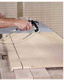
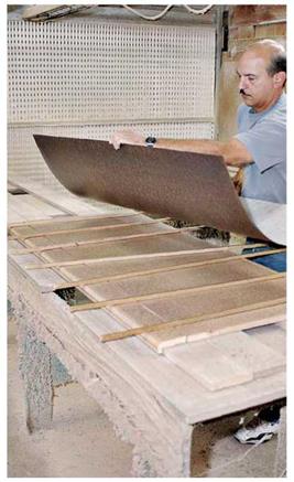
If you opt for a post-formed top, the installa­tion becomes a good deal simpler. The counter installer’s principal tasks will then be scribing the top of the backsplash so it fits flush to the wall, drawing mitered sections together with draw – bolts, and securing the counter substrate to the top of the base cabinet. However, as discussed in the next section, the first step in fitting counter­tops is taking careful measurements.

Unevenness or irregularities

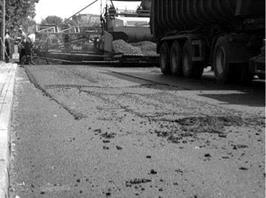
The last problem encountered when spreading SMA (and other asphalt mixtures, too) is unevenness caused by the approach of a paver on mixture residue left over on a bottom layer. Figure 11.33. shows how such residue builds up.

Different type of scrapers, sweepers, and other similar inventions fixed to the paver cannot fully protect it from causing unevenness. The care of cleanliness of the bottom layer is the responsibility of the paving crew. It consists not only in the skillful handling of a shovel but the proper coordination of mixture delivery from the dump truck into the paver hopper.

The material that is dumped in front of the paver also can cool before compac­tion, causing an internal porous area that can later trap water and then disintegrate the SMA layer.

11.8.2.5 Summary

Although thermal problems appear on almost every construction site and apply to any type of mixture, they seem to be underestimated. Examples of pavement damage presented in the previous pages, which developed during the construc­tion stages, should make us aware of their power to reduce a new pavement’s durability.

The use of infrared cameras has its strengths because it enables the spotting of potentially weak areas during construction when corrective measures can still be

image142

FIGURE 11.33 Remains of mixture left on a bottom layer resulting in unevenness of the finished course. (Photo courtesy of Krzysztof BlaZejowski.)

taken. Finally, it is worth finding the causes of damaged pavements that have pot­holes, bumps, and cracks appearing in the most unexpected places. Maybe it is time to view thermal differences as a potential cause of these defects.

ADHERING LAMINATE YOURSELF

image648

1. After rough-cutting the substrate and the laminate and touch-sanding them, spray both surfaces with a water-based contact cement. (Wear a respirator mask with organic vapor filters.) The curved piece at left, separated from the counter by a ’/4-in. spacer, will become the backsplash. The gap will enable the laminate to bend in a gentle radius.


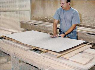
2. After allowing the contact cement to set for 15 minutes—surfaces are usually warmed to speed drying-place ’A-in. sticks atop the particleboard, and then place the laminate on the sticks. The sticks allow you to accurately position the laminate over the substrate without allowing cemented faces to touch.


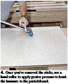
3. After measuring the laminate’s overlap and correcting its position, pull a middle stick and hand-smooth the laminate to the particleboard. Once there’s contact, you’re committed. Working outward from the middle, pull out sticks and smooth the laminate by hand.


image649image650

Подпись: 4. Once you've removed the sticks, use a hand-roller to apply greater pressure to bond the laminate to the particleboard.

irregular tile surfaces can be tricky to seal around sinks and splashbacks, so water can seep in and damage wood substrates.

Stone slabs include granite, marble, soapstone, limestone, and slate. Stone is naturally beautiful, but it’s also heavy, hard to work, and very expen­sive. Yet for all its heft, stone is relatively fragile and must be supported by a substrate—usually 14-in. plywood. Granite, the most popular stone, is available in slabs % in. and 1 !4 in. thick, up to 5 ft. wide and 10 ft. long. But because of its great weight, granite is usually installed in several sec­tions 6 ft. long or less. Section seams are filled with a caulk that’s color-matched to the granite, so seams are virtually invisible. To create a thicker edge, fabricators epoxy two layers of stone. When pattern matched and polished cor­rectly, the seams are almost invisible. Harder stones such as granite are highly scratch resist­ant. Softer stones, such as soapstone, can be scratched, but their softness allows you to easily sand out scratches or buff them out with steel wool. Stone is generally water resistant, though most stones are somewhat porous and so will stain unless protected. Penetrating sealants such as Aqua Mix Stone Sealer’s Choice® and Miracle Sealant’s 511 Porous Plus™ are well regarded in
the stone trade. For more recommendations, visit www. stoneworld. com.

Because stone is a natural material with inherent flaws and irregularities, few installers offer a warranty once an installation is complete. In the trade, it’s called "a tail-light warranty”; in other words, once the installer’s truck leaves your driveway, the warranty expires.

Concrete has become tres chic as a countertop material because it’s tough, reasonably priced, and highly malleable. It can be stained and pol­ished to look like exotic stone, factory-cast with colorful glass shards in the bottom of its mold. Or it can be cast directly atop a base cabinet.

Concrete weighs roughly the same as stone. However, because a concrete slab needs to be fully 1 /2 in. thick, you need to overbuild base cabinets to support the additional weight. (Stone tops need to be 1h-in. thick only along their front edge.) Because the bottom of in-place form molds can sag between supports until the concrete sets, it’s smart to add cross-counter webs to support the forms. Concrete is notorious for cracking and staining, but you can minimize those problems by reinforcing the slab adequately with steel or poly fibers and finishing the surface meticulously.

Concrete gurus praise Berylex®, an admixture that strengthens and internally waterproofs slabs

More About Trusses

While trusses may be a little off the title subject of this book, they can be an easy, quick, and relatively economic method of building a roof, and they marry well to a strong one – or two-story post-and-beam framework. Trusses can be engineered for a variety of roof shapes, as seen in Fig. 4.44. They are great for garages, and are frequently used now in housing. Normally, there is no attic space in a trussed roof, but, as we have seen, the use of special “attic trusses” can yield quite a bit of upstairs space. Attic trusses will be heavier and more expensive, because the bottom chord of the truss has to be strong enough to support living space. But the extra cost is quite effective on a “square foot per dollar” basis.

Manufactured trusses are not particularly pretty, but, since they are normally hidden, this isn’t really a problem. Ceilings can be applied to the underside of the trusses, and you can install blanket or blown-in insulation in the spaces between. So, although you wont see any beautiful beams overhead, you can have a light-colored ceiling to brighten the whole building, and plenty of easy insulation options.

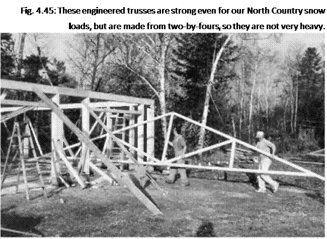
Подпись: Fig. 4.45: These engineered trusses are strong even for our North Country snow loads, but are made from two-by-foursr so they are not very heavy. It is important that trusses be stored vertically, or on a flat slab. Storing them on rough ground is the worst situation, as it puts all sorts of unwanted stresses on the truss plates, stresses that they are not meant to endure.

Lets have a last look (with Figures 4.45-4.51) at Chris Ryans garage project, where three people were able to install the 28-foot-long (8.5-meter-long) trusses without difficulty.