TWO WAYS TO SECURE A TOEKICK

As you install each cabinet, first transfer the stud center marks to the mounting rails on the back of the cabinet. Then drill through the marks, using a bit that’s thinner than the shanks of the mounting screws— or a countersink bit. Drill slowly to avoid splintering the plywood on the inside of the cabinet, or stop the countersink bit just as its point emerges. Then finish drilling from the other side.

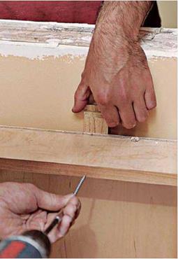
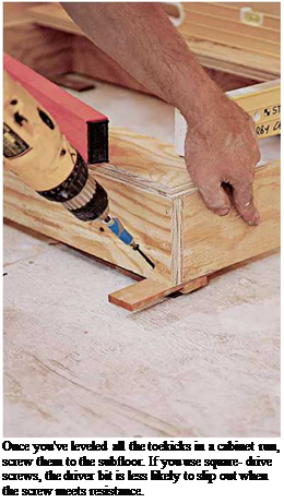
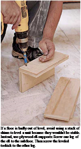
Подпись: Once you've leveled all the toekicks in a cabinet run, screw them to the subfloor. If you use square- drive screws, the driver bit is less likely to slip out when the screw meets resistance. Подпись: If a floor is badly out of level, avoid using a stack of shims to level a unit because they wouldn't be stable. Instead, use plywood ell-supports: Screw one leg of the ell to the subfloor. Then screw the leveled toekick to the other leg. 1111

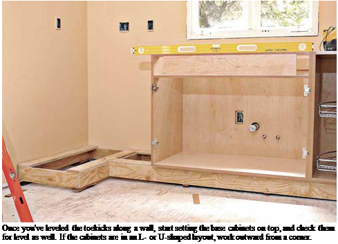
Подпись: Once you've leveled the toekicks along a wall, start setting the base cabinets on top, and check them for level as well. If the cabinets are in an L- or U-shaped layout, work outward from a corner. Setting cabinets with integral toekicks. If

your cabinets have integral (built-in) toekicks, be sure to review the preceding section on rough toekicks. Shimming units with integral kicks is similar, but more difficult. Basically, you’ll shim each cabinet under its sidewalls, front, and back. The difficulty arises because you can’t go back and adjust rear shims once you’ve installed the next cabinet. So take the time to level the top of each base cabinet perfectly. Otherwise, the order in which you install cabinets is the same for either type.

Setting base cabinets. If you’re installing a single run of cabinets along one wall, it really doesn’t matter where you start, except that if there’s a sink cabinet centered under a window, start there. If your cabinet layout is L – or U-shaped, start in a corner because there, where cabinet runs con­verge in a corner, their tops will need to line up perfectly if the countertop is to be level in all directions. So take pains to be sure that first cor­ner top is at the right height—in relation to the base cabinet layout line—and level in all direc­tions. Once that corner cabinet is perfectly level,

image637

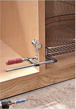
When you’re sure that base cabinets are at the correct height and leveled, align their front edges or face frames and use padded clamps to draw adjacent cabinets together. Then sink two wood screws through side panels to secure them.


image638

If the walls are irregular—and most are—shim behind the cabinet mounting rails before screwing them to the studs. Otherwise, back panels and rails could distort.


Подпись:you have a good shot at extending that level out­ward as you add cabinets.

When you’ve leveled the corner cabinet in all directions, you can screw it to the toekick and, through its mounting rails, to the studs behind it. But more often, carpenters prefer to “gang” cabi­nets together, lining up their tops so they’re level and, using quick-release clamps with padded jaws, aligning and drawing the cabinet edges or face frames together. Once you’ve lined up the cabinet edges and frames, use two wood screws to join them. Drill pilot holes first with a counter­sink bit so the screw heads will be flush. If cabi­net panels are 3з4 in. thick, use 114-in. screws to join them, so the screw points don’t pop through.

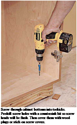
After securing the cabinet edges and frames, check the cabinet tops for level and height one last time. Then, depending on the type of cabinet, screw the cabinet bottoms to the toe – kicks, or screw integral toekicks to the subfloor. Finally, screw the cabinet backs to the studs, through the pilot holes you predrilled. If a wall is wavy, shim low spots behind the mounting rails; otherwise, screws could distort the mounting rails and possibly misalign the cabinet boxes. Screws should sink at least 1 in. into the studs, so use #8 screws that are 212 in. or 3 in. long.

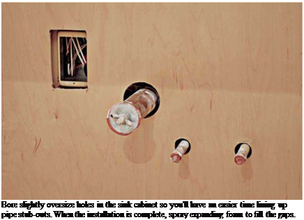
Подпись: Bore slightly oversize holes in the sink cabinet so you'll have an easier time lining up pipe stub-outs. When the installation is complete, spray expanding foam to fill the gaps.

Don’t use drywallscrews because they don’t have much shear strength. If your base cabinets have top and bottom mounting rails, drive two screws per stud to anchor the cabinets—in other words, sink a screw each time a mounting rail crosses a stud. Later, you can use wood-grained, stick-on screw covers to hide the screws.

Setting sink bases. Sink bases with back panels take a bit more work because you must bore or cut through the back panel for pipe stub-outs and
electrical outlets, if any. Perhaps the easiest way to transfer the locations of those utilities to the back of the cabinet is to position the cabinet as close as you can to layout marks on the wall, and then place a spirit level behind it. Holding the level vertically, place it next to each stub-out, plumb the level, and then mark that pipe’s posi­tion on the wall and on the cabinet’s back stringer. Pull the sink base away from the wall, measure how far each stub is below the layout line, and measure down an equal amount on the back of the cabinet. Use a slightly oversize hole saw to bore holes, stopping when the saw’s center bit comes through the inside of the cabinet. Finish drilling from the inside of the back panel to avoid splintering it.

Setting islands. Kitchen islands are installed much the same as other base cabinets, except that they can’t be screwed to studs. Therefore, the rough toekick must be sturdy and well attached to the subfloor. For that reason, use ell-supports to level rough toekicks or integral toekicks and anchor them to the subfloor.

Here, glue and screw the ells to the subfloor after snapping chalklines to show you exactly where the island will sit. Place an ell at least every 18 in. to 24 in. and, to further bolster rough toekicks, add crosspieces at the same interval. You can’t overbuild a kitchen island, especially if you’ve got kids who think cabinets are jungle gyms.

image641

INSTALLING BASE CABINETS

Cabinet installers wrangle about whether it’s easier to install base or wall cabinets first. If you hang the wall units first, you won’t need to lean over the base cabinets as you work. Whereas if you install the bases first, you can brace the bottom of the wall cabinets off the bases and thereby install the uppers single-handedly.

There isn’t one right answer, but the photos on p. 318 make a convincing case for hanging the wall cabinets after installing stone countertops. Above all, be patient. Setting cabinets means endlessly checking and rechecking for level, fussing with shims, and so on. So don’t begrudge the time it takes. You can’t hurry love or cabinets.

Setting rough toekicks. If your cabinets have separate toekicks, install them first, starting at the highest point on the floor—as you did dur­ing layout. Make the toekicks as long as possi­ble to minimize joints because joints tend to sag and separate under load. Level the toekicks side to side, front to back, and from section to section. Shimming is an inexact science: As a rule of thumb, shim under the corners and in the middle of a span—roughly every 18 in. to 24 in. A 24-in.-deep base cabinet is typically supported by a 20-in.-deep toekick.

image633

Because you’ll be securing both base and wall cabinets to stud centers, use an electronic stud-finder to help locate them.

If floors are seriously out of level—say, 1 in. in 8 ft.—construct several ell supports such as the one shown in the top right photo on p. 308. Screw one leg of each ell to the subfloor, level the top of the toekick, and then screw the side of the toekick to the upright leg of each ell. Ells aren’t hard to construct, and they’re far more stable than a 1-in.-high stack of shims. Once you’ve lev­eled the toekicks, place the base cabinets atop them and see how everything fits together. If this dry run looks good, set aside the cabinets and screw the toekicks to the subfloor.

Efficiency of the Monte Carlo algorithm

Efficiency of the Monte Carlo algorithm Подпись: (6.71)

Referring to Monte Carlo integration, different algorithms yield different esti­mators for the integral. A relevant issue is which algorithm is more efficient. The efficiency issue can be examined from the statistical properties of the esti­mator from a given algorithm and its computational aspects. Rubinstein (1981) showed a practical measure of the efficiency of an algorithm by t x Var(©), with t being the computer time required to compute ©, which estimates ©. Algorithm 1 is more efficient than algorithm 2 if

If the computational times for the two algorithms are approximately equal, comparison of efficiency can be made by examining the relative magnitude of the variances. When the true variances are not known, which is generally the case, sample variances can be used. Without considering the computational time, it can be shown that the sample-mean algorithm using X ~ U(a, b) is more efficient than the hit-and-miss algorithm (see Problem 6.25).

Insulating between floor joists in crawl spaces

Floor insulation is important in a house with a crawl-space foundation. Often, it is not enough just to put insulation under the floor, because cold can pass through the rim joist. Unless batts fill the entire joist space, cold air can seep in through the rim joist and over the top of the batts, making the floor uncomfort­ably chilly.

To prevent this from happening, you can either hold the insulation high or roll it up to cover the rim joist (see the top illustration on p. 206). Better yet, use a thicker batt with a higher R-value to fill the entire joist space and butt up against the rim joist.

When insulating between I-joists, make sure the insulation is wide enough to extend all the way from web to web. If you live in a cold part of the country and yoifre using kraft paper-faced insulation, the paper should face toward the floor. This may seem back-

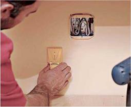
Insulating between floor joists in crawl spacesINSULATE AROUND ELECTRI­CAL BOXES. First, divide the batt into two layers instead of compressing it. Slide the back layer behind the out­let box (see the photo far left), then cut out the front layer to fit around the box (see the photo near left). This technique also works for installing fiberglass batts around electrical wires and plumbing pipes.

[Photo by Steve Culpepper, courtesy Fine Homebuilding magazine, – The Taunton Press, Inc.]

Подпись: Helping HandПодпись: Eliminate gaps when installing fiberglass insu-lation. Gaps around outlet boxes and along a wall's bottom or top plate can let in a lot of unwanted air. A gap of just Ye in. along both sides of a fiberglass batt can cut the insulation's effectiveness by 50% or more!

ward, but the paper acts as a vapor barrier (more on that later) and must face the heat, so to speak. If you live in an area where cooling (air-conditioning) is an issue for a majority of the year, staple the kraft paper to the under­side of the joists.

It can be a pain to install batts of insulation under a floor, because there is often not much space between the ground and the joists. Its not a lot of fun to lie on your back and install fiberglass batts! Sometimes, especially in dry dimates, it’s possible to insulate the floor before you sheathe. The drawback with this technique is that subcontractors (plumbing and heating, especially) may not treat your work with TLC. In rainy Oregon, we wait to insulate until after the shingles are on and the house is closed in. Either way, take your time, and make sure that underfloor insulation batts are installed properly and securely around all pipes and conduits.

There are a number of ways to hold under­floor batts in place (see the bottom illustration on p. 206). In Oregon, its common to nail strips of lath every 12 in. to 16 in. o. c. across the bottom of the joists once the insulation is installed. Its a lot of work, but it holds the batts securely without compressing them. Another way is to staple polypropylene (not cotton) twine or mesh to the bottom edges of the joists. I’ve also seen people staple chicken wire or hardware cloth across the joists. Still another option is to use wire supports designed specifically for the job. Called light­ning rods or tiger teeth, these wire supports clip between joists and bow up against the batts, holding them in place. Installed about every 12 in. or so, they do a good job of keep­ing the batts in place for years to come. Just take care not to compress the batts when installing the rods.

BURNHARDT

The Burnhardt is essentialy the Epu turned sideways. It includes all of the same amenities but no wheels. 1

Square feet: 117

House width: 8’

House length: 19’

Road Height: 13’-5”

Dry Weight: 5400 lbs

Porch: 3’x 7%’

Great Room: 6’ x 6%’ Kitchen: 6’ x 61/2’

Bathroom: 3’x 6’

Ceiling height: 6’ 6710” 6” Loft height: 3’ 8”

-sizes are approximate

Single-Support Installation

The correct installation of sign-support assemblies is dependent upon the type of sup­port post, the type of soil present, and the impact performance design of the sign assembly. Installation instructions are contained in standard state drawings and, for proprietary devices, from signpost manufacturers. Proper installation practices for the most common types of single support assemblies are presented in subsequent sections.

U-Channel Posts. The most common method of installing U-channel posts is by direct burial. The burial can be achieved by mechanical post drivers, by sledgehammer, or by digging a hole and backfilling. If the post is to be placed by driving into the ground, then a driving cap should be used to prevent damage to the end of the U-channel. Drive or place the posts at least 3 ft (900 mm) but no more than 3.5 ft (1100 mm) into the ground to make it easier to pull out damaged posts.

U-channel posts can also be installed as two-piece assemblies consisting of an anchor base and the post support. The advantage of the two-piece assembly is that the post will break off from the anchor piece upon impact. This often improves safety upon impact, makes repairs easier, and makes it possible to salvage portions of a damaged U-channel post. An anchor base assembly is especially advantageous when the post is placed in a paved area, such as a concrete median. The anchor piece should not extend more than 4 in (100 mm) above the ground to prevent snagging the vehicle undercarriage.

The anchor piece can be directly driven, buried 3 ft (900 mm) in the ground, or embedded 2 ft (610 mm) in a concrete foundation that is 8 in (200 mm) in diameter and 2.5 ft (760 mm) deep. The signpost can be attached to the anchor piece by a generic splice or the use of commercially available devices.

Figure 7.32 presents a generic method of attaching the signpost to the anchor piece. The signpost overlaps the anchor piece by 6 in (150 mm) to provide stability against the environmental loads. Since the anchor piece cannot extend more than 4 in (100 mm) above the ground, this means that the signpost is at least 2 in (50 mm) below ground level. The signpost is placed behind the anchor stub, and the posts are attached together

FIGURE 7.32 Generic method of splicing sign support to anchor piece. (a) Drive anchor post to within approximately 12 in (300 mm) from top of ground and install bolt with lock washer in fifth hole from top. (b) Drive post to 4 in (100 mm) or less from ground, and install bolt in first hole from back of post to allow room for sign post to be attached. (c) Install bolts 4 in (100 mm) apart with ground stub no higher than 4 in (100 mm) above ground. (d) Place signpost behind anchor stub, place bolts through first and fifth hole of sign post, use cut washers, and tighten securely.

with two /-16-in (8-mm) bolts spaced 4 in (100 mm) apart. Extra %s-in (8-mm) nuts are used as spacers between the two post pieces to prevent binding during impact.

A number of commercial splicing devices for installing two-piece U-channel assem­blies are also available. Figure 7.33 provides installation information on the Eze-Erect system available from Franklin Steel, and Fig. 7.34 is information on the Minute-Man coupling from Marion Steel [35, 36].

The following guidelines should be followed for the installation and use of U-channel posts:

• If U-channel posts are driven into the ground, they should not be embedded more than 42 in (1100 mm), to make it easier to pull out damaged posts.

• Use a drive cap to drive the U-channel into the ground to prevent damage to the post end.

FIGURE 7.33 Installation with Eze-Erect U-channel coupling. (a) Drive anchor post to within 12 in (300 mm) of ground level, attach retainer spacer strap through bottom hole of strap and sixth hole of anchor post, and rotate strap to the side. (b) Drive anchor post to within 4 in (100 mm) of ground level and rotate strap to vertical position. (c) Attach signpost with two bolts, nuts, and lock washers in bottom and fifth hole; insert one bolt through signpost and bottom of long slot in strap; and tighten all nuts snugly before completely tightening assembly. (d) Finished assembly.

• If an anchor base is used, do not leave the anchor stub protruding more than 4 in (100 mm) above ground level.

• The generic splice should provide an overlap of 6 in (150 mm) with the anchor base. This results in 2 in (50 mm) of the signpost extending below ground level. The signpost is fastened to the anchor stub with /8-in (8-mm) grade 9 bolts spaced 4 in (100 mm) apart. The signpost and anchor piece should be separated with a %s-in (16-mm) spacer to prevent possible binding of the posts upon impact.

FIGURE 7.34 Minute-Man coupling for use with RIB-BAK U-channel signposts. Erection steps:

(1) Bolt couplers to both Minute-Man groundpost and accompanying sign support using backup plates

for reinforcement. (2) Drive groundpost into the ground until only 3 in (75 mm) remain above ground

[1 in (25 mm) of bottom coupler is buried]. (3) Raise sign and connect Minute-Man’s top and bottom

sections by inserting shear pin. To finish, simply tighten shear pin bolt.

• Anchor pieces one size larger than the sign post will help prevent damage to the anchor piece upon impact.

• The Florida splice requires an overlap of 8 in (200 mm). This results in embedding of 4 in (100 mm) of the signpost below ground. The splice is secured with /8-in (10-mm) A307 bolts, 2 in (50 mm) long, spaced at 6 in (150 mm) center to center. A 58-in (16-mm) spacer is placed between the anchor piece and the signpost. The use of 58-in-diameter (10-mm) bolts requires that the post holes be reamed in order to insert the bolts. Reaming destroys the corrosion protection of the hole, necessitating the application of zinc-rich paint paste to prevent corrosion.

• If commercial splices are used, the manufacturer’s installation instructions must be closely followed for proper impact performance.

• The frangible bolt provided with the Minute-Man must be used for proper impact performance. Do not replace this bolt with a regular steel bolt.

• It is not recommended to interchange signposts and anchor stubs of different manufac­turers when there is variation in cross-section between the two sections. No crash tests have been done on mixed anchor stubs and signposts. The difference in cross-section may be sufficient to cause problems in nesting under some splice orientations.

• The signpost should be placed behind (on the nonimpact side of) the anchor stub for U-channel anchor base assemblies.

• Splices that are performed above the anchor piece to extend short pieces of U-channel or to piece together salvaged U-channel are not recommended. One-piece U-channel posts perform better under impact than posts that have been spliced above the anchor stub. A splice in the impact zone can strengthen the post and degrade its impact performance. Splices above the impact zone can open, allowing the sign panel to take an unpredictable and potentially hazardous trajectory. The splice can also open with the lower end of the upper post section penetrating the impacting vehicle. If splices above the anchor piece are used with U-channel, it is important that the following conditions are met [37]:

The splice does not extend below ground level.

The overlap is approximately 18 in (460 mm) fastened by four %s-in (8-mm) bolts, with two bolts, through the holes nearest the ends, at each end of the splice. Spacers 58 in (16 mm) thick should be placed over the bolts between the spliced pieces of U-channel.

FIGURE 7.35 Allowable but not desirable splicing of U-channel sign supports. (a) Limits on lower splice. (b) Limits on upper splice. Dimensions shown as mm. Conversions: 400 mm = 16 in, 460 mm = 18 in, 500 mm = 20 in.

A splice that is mostly below a vehicle bumper height should have a maximum top elevation of 20 in (500 mm), and a splice that is mostly above the bumper should have a bottom elevation of 16 in (400 mm) or above. A diagram of these recom­mendations is presented in Fig. 7.35.

Square Steel Tubes. Square steel tubes are available from a number of manufacturers in perforated, and punched but not perforated, styles [38, 39, 40]. Two of the major manufacturers of square-tube posts are Unistrut, with the brand name Telespar, and Allied Tube and Conduit, with the perforated Square Fit and the nonperforated Quick – Punch tubes. Square-tube sign supports can be installed as one-piece direct burial assemblies and with anchor pieces. The anchor piece assemblies have the advantages of more predictable performance upon impact, a larger range of permissible sizes, and reduced maintenance required for repair after impact. Figure 7.13 shows different installation methods.

Square steel-tube sign supports up to 2.25 in X 2.25 in (57 mm X 57 mm) in size can be installed by direct burial. Sizes larger than 2.25 in X 2.25 in (57 mm X 57 mm) require an anchor base assembly to provide acceptable impact performance character­istics. The most common method of direct burial is by driving directly into the ground, using a driving cap to protect the end, by mechanical drivers or a sledgehammer. Drive or place the square tube at least 36 in (900 mm) deep but no more than 42 in (1100 mm) into the ground to make it easier to pull out damaged posts.

Repair of damaged square tube is easier to perform when an anchor base assembly is used. The anchor base assembly for square tube usually consists of a 30-in-long (760-mm) anchor piece, one size larger than the signpost, and an 18-in-long (450-mm) stiffening sleeve, one size larger than the anchor piece. The sleeve provides a double­walled anchor base that helps prevent damage to the anchor assembly and makes the breakaway characteristics of the signpost more predictable. Acceptable impact perfor­mance can also be obtained by the use of only the anchor piece, but damage to the anchor piece and increased maintenance are more likely to occur than when using a stiffening sleeve. Sizes larger than 2.5 in X 2.5 in (64 mm X 64 mm) should not be used for breakaway performance with the anchor breakaway design. The anchor piece must not extend more than 4 in (100 mm) above ground level. The installation proce­dures for the square-tube anchor base system are provided in Fig. 7.36.

FIGURE 7.36 Installation procedure for square-tube anchor base assemblies. (a) Drive the anchor post 6 to 8 in (150 to 200 mm) into the ground, remove post, and knock out soil from post end. (b) Reinsert post into hole and drive with stiffer sleeve to 1 to 2 in (25 to 50 mm) above ground level. (c) Attach sign to signpost, insert 6 to 8 in (150 to 200 mm) into anchor, and fasten to base.

In addition to the telescoping anchor bases, made from larger sizes of square tubing, there are heavy-duty anchor bases commercially available. These bases can be used in hard or rocky soil conditions that can present problems for driving the regular-sized tubing as anchor pieces.

The following guidelines should be followed for the installation and use of square steel-tube signposts:

• Do not directly bury square steel tubing that is larger than 2.25 in X 2.25 in (57 mm X 57 mm). If a sign requires a larger post, use an anchor base system.

• Repair of the square steel-tube sign assembly is much easier if an anchor base system is used. The stiffening sleeve helps reduce damage to the anchor and provides a strengthened base for reliable impact performance.

• The anchor assembly should be driven or placed into the ground with only 1 to 2 in (25 to 50 mm) protruding above ground level. This will expose one or two holes for fastening the sign assembly, reduce vehicle sagging, and ease repair.

• If driving the post or anchor base into the ground, use a drive cap to protect the exposed end. If a drive cap is not used, the exposed end will become distorted, inhibiting insertion of the telescoping tube.

• Do not install a two-piece anchor assembly if the top of the anchor piece and sleeve is not flush or if the holes are misaligned. The bolts will be difficult to insert and the higher piece may bend upon impact, damaging the anchor assembly.

• Do not overtighten the bolts that fasten the signpost to the anchor assembly. Tightening the bolts too much will distort the tubing and hinder the removal or insertion of the signpost into the anchor assembly.

• Sections of square steel tube can be spliced together to allow the reuse of damaged posts. The splice is made by using a 12-in-long (300-mm) section of tubing one size smaller than the tubing to be repaired. The 12-in (300-mm) section is inserted halfway into one of the tubes and secured with two drive rivets or one bolt. The second tube is then slipped over the free end of the 12-in (300-mm) section and fastened in place.

• Square tube can be used to install signs in areas of concrete or asphalt by drilling or chipping through the surface and driving an anchor assembly in place. An anchor base is recommended in concrete or asphalt areas to make repair easier in case of impact.

Wooden Posts. The most common wooden supports for single signpost installation are the 4-in X 4-in (90-mm X 90-mm) shaped and the 4-in-diameter (100-mm) round posts. These posts should be directly buried to a depth of at least 36 in (910 mm) (Fig. 7.12a). Deeper burial is often performed to reduce vandalism. Posts larger than the 4-in X 4-in (90-mm X 90-mm) and the 4-in-diameter (100-mm) posts require drilled holes to reduce the cross-section and embedment in concrete so as to safely break away during impact. The requirements presented in Tables 7.8 and 7.9 should be followed for the installation of rectangular shaped and timber posts.

The use of!2-in-thick (13-mm) Styrofoam for the concrete foundation (Fig. 7.12b) eases the removal of broken stub pieces [41]. An example of hole placement to achieve a weakened cross-section is also presented in Fig. 7.12b [42]. The bottom hole should never be centered more than 4 in (100 mm) above the ground, because the stub piece must remain at 4 in (100 mm) or less after impact. Rectangular-shaped posts are placed with the long post dimension parallel to the direction of travel. The holes of the proper size for the post are drilled perpendicular to the expected direction of impact.

Steel-Pipe Posts. Steel-pipe (schedule 40) posts smaller than 2 in (50 mm) internal diameter can be directly buried and still provide acceptable impact performance. As

Post size, Embedment Comments and required

in (mm) type and depth post modifications

indicated in Art. 7.3.6, a plate 4 in X 12 in X 0.25 in (100 mm X 310 mm X 6 mm), or two sign clamps, should be bolted or welded to the pipe, beneath ground level, to prevent rotation due to wind. Schedule 40 steel-pipe supports should be direct buried, with the attached earth plate, to a depth of at least 42 in (1070 mm) to provide accept­able performance upon impact.

A breakaway collar assembly is required for schedule 40 standard pipe that is equal to or greater than 2 in (50 mm) ID. The breakaway collar can be made by the use of a regular pipe coupling or reducing coupling [43]. The reducing coupling is recom­mended since it reduces the probability of damage to the anchor piece, thereby easing repair. The anchor piece is usually one size larger than the signpost. The anchor assembly consists of a 24-in-long (610-mm) anchor piece placed in a concrete footing that is 30 in (760 mm) deep and 12 in (300 mm) in diameter.

In addition to standard steel pipe, there are round steel-tube sign supports available from a number of manufacturers, with a wall thickness of 12 gauge or less and designed for use in an anchor system. Commercial anchor systems, such as the Poz-Loc, can be used for the round steel tubes and for standard pipe 2 in (50 mm) or less in size [44]. The use of commercial anchor systems requires closely following the manufacturer’s instructions for proper performance.

A summary of steel-pipe sign-support installation recommendations is provided in Table 7.10. Also consider the following guidelines:

Post diameter, in (mm)

Embedment type and depth

Comments and required post modifications

4

(100)

Direct burial to at least 36 in

(920 mm)

No holes required.

5

Placed in soilcrete foundation

Holes must be drilled perpendicular to

(127)

of 18 in (460 mm) diameter and 4.5 ft (1100 mm) deep

probable impact path: one 2-in (50-mm) hole at 4 in (100 mm) and one 2-in (50-mm) hole at 18 in (460 mm) above ground level.

6

(150)

Direct burial to 5 ft (1500 mm)

Holes must be drilled perpendicular to probable impact path: one 2-in (50-mm) hole at 4 in (100 mm) and one 2-in (50-mm) hole at 18 in (460 mm) above ground level.

6.5

(165)

Direct burial to 5 ft (1500 mm)

Holes must be drilled perpendicular to probable impact path: one 1.25-in (32-mm) hole at 4 in (100 mm) and one 1.25-in (32-mm) hole at 18 in (460 mm) above ground level.

7

(178)

Direct burial to 5 ft (1500 mm)

Holes must be drilled perpendicular to probable impact path: one 2-in (50-mm) hole at 4 in (100 mm) and one 2-in (50-mm) hole at 460 mm above ground level.

7.5

(190)

Direct burial to 5 ft (1500 mm)

Holes must be drilled perpendicular to probable impact path: one 2.75-in (70-mm) hole at 4 in (100 mm) and one 2.75-in (70-mm) hole at 18 in (460 mm) above ground level.

• Standard steel pipe (schedule 40) that is equal to or greater than 2 in (50 mm) ID must be of breakaway design with anchor base.

• Anchor pieces should be placed in a concrete foundation and be one size larger than the signpost. The breakaway mechanism can be achieved by the use of a reducing coupling. The top of the coupling should not be more than 4 in (100 mm) above ground level.

Also consider the following:

• Do not install aluminum round signposts larger than 3.5 in (90 mm) diameter. Recent tests show that the larger aluminum post sizes fail in weak soil conditions.

• Anchor plates or two sign clamps configured to encircle the post should be used below ground level to prevent rotation due to wind loads.
Equipment

Water Treatment Equipment

Water Purification in Standard Construction

Poor indoor air quality is not the only form of pollution that affects human health. Our water sources, both public supplies and pri­vate domestic wells, have also become increas­ingly contaminated. Public concern about water quality has increased dramatically. In late 2005, the Environmental Working Group (EWG) found in an analysis of more than 22 million tap-water quality tests (most of which were conducted to meet EPA compliance) that 260 contaminants were detected in water served to the public.1

Of the contaminants identified in the EWG study, the EPA has set enforceable health lim­its for 114 contaminants and nonenforceable, recommended standards for five. More than half (141) of the total contaminants identi­fied are unregulated and without safety stan­dards. The statistics reported by EWG are believed to represent an underestimate of the exposure of American consumers to unregu­lated contaminations in the nations tap water. Not considered in the study were unregulated pharmaceuticals and personal care product chemicals, which, surprisingly, were found in the tested water. The good news is that EWGs analysis found over 90 percent compliance with enforceable health standards.

Water Quality Parameters

Water purification is not standard in home construction, and unless you specify water testing and purification they will not be in­cluded. Although water purification is usually considered an “extra,” whole-house systems are best planned for and installed at the time of construction. But before you can contem­plate options for water quality improvement, you need to know what is in your water.

This is relatively easy to determine if you are on a city or other public water system, but water in private wells is not regulated. The Safe Drinking Water Act (SDWA), passed in 1974 and amended in 1986 and 1996, gives the

Environmental Protection Agency (EPA) au­thority to set drinking water standards for public water systems that provide water for human consumption through at least 15 ser­vice connections or regularly serve at least 25 individuals. To find out more about regulated water contaminants and to learn about the po­tential health effects and the sources of these contaminations, consult the EPAs Drinking Water Contaminants website.2

There are two categories of EPA drink­ing water standards: primary and secondary. Primary standards (NPDWRs) are legally – enforceable standards that apply to pub­lic water systems and are classified into the following categories: microorganisms, disin­fectants, disinfection byproducts, inorganic chemicals, organic chemicals, and radionu­clides. Primary standards protect drinking water quality by limiting the levels of specific

Further Reading and Services

Biointegral Resource Center (BIRC), PO Box 7414, Berkeley, CA 94707,510-524-2567. Useful source of information on pesticides and alternative pest treatments.

Moses, Marion. Designer Poisons: How to Protect Your Health and Home from Toxic Pesticides. Pes­ticide Education Center, 1995. A sobering expose of specific pesticides and the chronic health ef­fects that can result from their use, with useful information on safer alternatives.

National Coalition Against Misuse of Pesticides, 701 E. Street SE, Suite 200, Washington, DC 20003, 202-543-5450, info@beyondpesticides. org. Pro­vides useful information about pesticides and nontoxic alternatives.

Northwest Coalition for Alternatives to Pesti­cides (NCAP), PO Box 1393, Eugene, OR 97440, 541-344-5044, pesticide. org. Provides a compre­hensive information service on the hazards of pesticides and alternatives to their use. Main­tains an extensive library of over 8,000 articles, government documents, videos, and other refer­ence materials, and offers information packets, fact sheets, and the quarterly Journal of Pesticide Reform.

Olkowski, William et al. Common Sense Pest Con­trol: Least-Toxic Solutions for Your Home, Gar­

den, Pets, and Community. Taunton Press, 1991. Comprehensive, well-documented information on integrated pest management and least-toxic control for all kinds of pests.

Schultz, Warren. The Chemical-Free Lawn: The New­est Varieties and Techniques to Grow Lush, Hardy Grass. Rodale Press, 1989. Techniques for grow­ing lush and hardy grass without using pesti­cides, herbicides, or chemical fertilizers.

Chart 10.1: Common Pests and Management Strategies

Pest

Types of damage

Modus operandi

Recommendations

Termites

(subterranean)

• Structural damage

•Tunnels created in wood

• Require moist condi­tions

* Termites must be able to get from the soil into the wood structure via earthen tubes; they do not live in wood

• Control moisture

• Seal off wood from ground contact

• Use termite shielding, sand barriers, and/or termite-resistant sill plates

Termites (dry wood)

* Structural damage

•Tunnels created in wood

* Can access house through walls

• Live in wood

•Tight construction

• Caulked joints

• Boric acid in framing

Rats

• Carry disease

• Destroy food supply

• Breed quickly

• Require hole V2" wide to enter

• Screen all points of entry, including openings along pipes and wires

• Make home weathertight

• Ground floors should be elevated 18" above grade

• Subterranean concrete floors should have a mini­mum thickness of 2"

• Use wire mesh under wood floors

• Use noncombustible cement stops between floor joists

Mice

• Chew through electri­cal wires, causing fire hazard

•Transmit pathogens

• Breed quickly

• Require dime – size openings

• Feed on dry foods, grains, clothing, paper

• Usually seek indoor habitat when outdoor climatic conditions become severe

• Seal all holes and crevices, especially where pipes and wires protrude through surfaces

Chart 10.1: Common Pests and Management Strategies (corn’d.)

Pest

Types of damage

Modus operandi

Recommendations

Ants

(carpenter)

• Create nests inside walls and ceilings, under siding, and where wood and soil are in contact near foundations

• Infest both hardwood and softwood

* Require wood with high moisture content (minimum 15%)

• Use kiln – or air-dried lumber and keep it dry

■ Prevent contact between structural wood and earth

• Allow for proper ventilation of damp areas

Bees

(carpenter)

• Chew on wood

• Burrow into structural members and exposed wood elements

• Enjoy untreated ex­posed wood (especially softwoods)

• Paint or varnish exposed wood (sills, trim, etc.)

• Fill in holes and indentations in wood

Beetles

(wood-boring)

• Bore through wood

• Require moisture con­tent in wood to be 10 to 20%

• Prevent moisture changes and temperature fluctuations

• Allow for good ventilation in attic spaces

• Keep roof frame and sheathing dry

• Use air – or kiln-dried lumber

• Seal wood

Cockroaches

• Invade food storage areas such as kitchens and cupboards ■ Can carry disease-caus­ing organisms

• Most species prefer warm, moist areas

• Avoid moisture and decayed organic buildup in or near home

• Use boric acid in framing in areas prone to infes­tation

• Use screens on vents and windows

Fungus (wood decay)

• Attacks and weak­ens wood, leaving it susceptible to invasion by wood-boring and wood-eating insects

■ Grows best at tempera­tures between 50 and 95 degrees F • Requires a minimum of 20% moisture

• Allow for proper roof insulation

and ventilation to prevent condensation

• Seal wood joints at corners, edges, and intersec­tions

• Prevent moisture accumulation near pipes, vents, and ducts

• Do not use wood containing mold in construction

• Seal all wood exposed to the elements

• Use proper ventilation strategies

to control moisture buildup generated by human activity

• Use building products and procedures that al­low moisture vapor to escape rather than being trapped

Repeated Load Triaxial Tests – Unbound Granular Aggregates

Unbound granular materials, which are continuously graded materials containing fines, are also sensitive to moisture. Examples of influence of moisture on the

Fig. 10.8 CBR values related to moisture (water) content and compaction curves for typical soils: (a) well-graded silty sand with clay, (b) uniform fine sand, (c) heavy clay (Head 1994). @ 1996, copyright John Wiley & Sons Limited. Reproduced with permission

resilient modulus and on the permanent deformation of 3 French unbound granu­lar materials, of different mineralogy (hard and soft limestone, micro-granite) are shown in Fig. 10.10. All 3 materials present a decrease of their resilient modulus as the water content approaches the modified Proctor Optimum (wOPM), but the sen­sitivity to moisture is much more important for the limestone than for the igneous rock material (micro-granite). The permanent axial strains become very large for all 3 materials when the water content approaches wOPM.

Other examples, showing the influence of water content on the permanent de­formation and modulus of elasticity of several unbound granular materials from Slovenia, are presented in Fig. 10.11. Again, the permanent strains appear to be more sensitive to moisture than the resilient modulus.

Several studies carried out in France on a large number of different unbound granular materials have shown that their sensitivity to moisture is strongly related to their mineralogical nature, and is particularly important for soft limestone materials. This is illustrated in Fig. 10.12 which presents values of resilient modulus obtained for different natures of granular materials and different water contents.

The igneous materials present relatively low resilient moduli (generally between 300 and 500 MPa), but are not very sensitive to moisture. The soft limestone materi­als present significantly higher moduli at low water contents (up to 1000 MPa), but these moduli drop when the water content approaches the optimum (wOPM).

Ekblad (2004) investigated the influence of water on the resilient properties of coarse unbound granular materials in the saturated as well as the unsaturated state. This study was limited to one type of aggregate of different gradings (with

I In situ water content

Fig. 10.10 Influence of water content, w, on the resilient modulus, Mr, and permanent axial strains, A1c, of 3 French unbound granular materials: hard limestone, soft limestone and microgranite (Hornych et al., 1998)

Note: A1c is a level of strain anticipated once plastic strain has stabilised.

maximum particle size 90 mm). The aggregate comes from Skarlunda in Ostergotland in Sweden. Ekblad’s tests on unbound granular materials of differ­ent granulometric curves showed that the influence of water content on resilient properties depends on the material grading.

First, the dependency of resilient modulus, Mr, on confining stress was estab­lished (Fig. 10.13). Increased confining pressure leads to a substantial increase in resilient modulus. Confining pressures of 100 kPa were reached by Ekblad. Triax­ial tests at different water contents were also performed. The water content was successively increased from an initially low water content to a soaked condition (representing full saturation) and then the sample was allowed to drain freely. All these triaxial tests were performed at a confining pressure of 40 kPa (Fig. 10.13).

Finally, to achieve a summary comparison, the resilient response for a mean nor­mal stress of 100 kPa at a confining pressure of 40 kPa was calculated as a function of the degree of saturation. From Fig. 10.14 it can be observed that the relative reduction in modulus seems to depend on the grading coefficient, with a lower

Fig. 10.12 Sensitivity to moisture of unbound granular materials of different origin (Hornych et al., 1998)

grading parameter (i. e. a higher proportion of fine particles) yielding a larger mod­ulus reduction upon saturation.

Safety on the Job WORKING WITH FIBERGLASS INSULATION

Safety on the Job WORKING WITH FIBERGLASS INSULATIONSafety on the Job WORKING WITH FIBERGLASS INSULATION

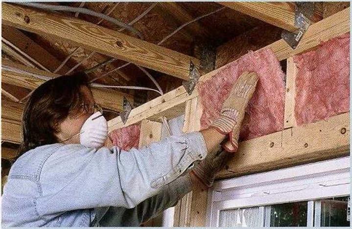
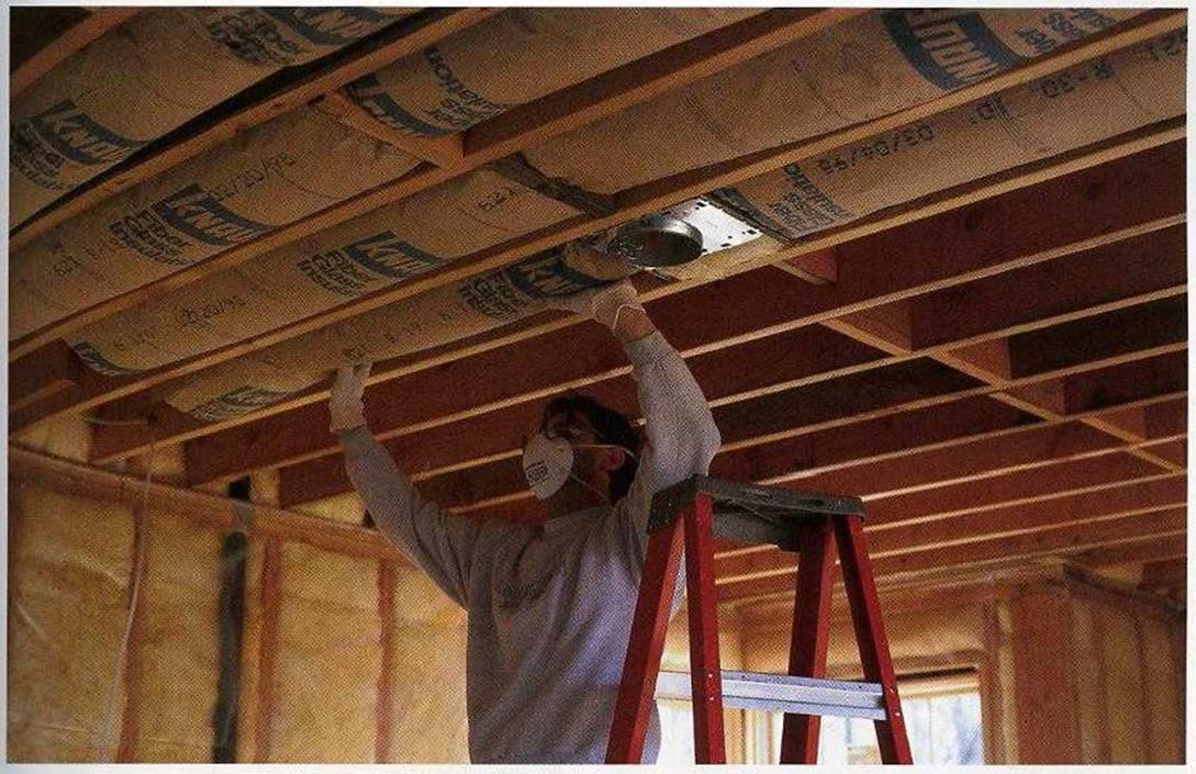
GLASS FIBERS CAN irritate your skin and damage your eyes and lungs, so safety precautions are very important when working with fiberglass insulation. Cover your body with a loose-fitting, long-sleeved shirt and long trousers, and wear gloves and a hat, especially while insulating a ceiling (see the photo below). It’s best to wear a pair of quality goggles, too, because eyeglasses alone don’t keep fiberglass particles out of your eyes. Make sure the goggles fit properly; goggles that fit well don’t fog over. Wear a good-quality dust mask or, better yet, get yourself a respirator. Don’t scratch your skin while you’re work­ing (you’ll just embed glass fibers), and be sure to wash up well when you are finished.

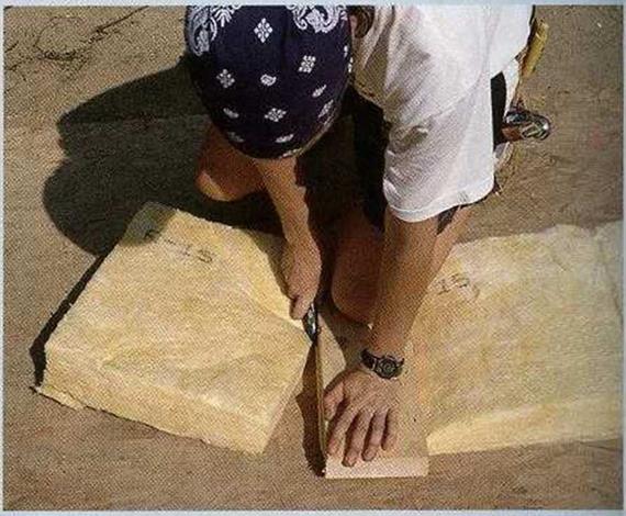
Cutting Batts. Cutting fiberglass batts to size is straightforward. The best tool for the job is a sharp utility knife. Note that I said "sharp." A dull blade will tear paper-faced batts, and torn paper doesn’t work as a vapor barrier. A sheet of plywood or OSB makes a good cutting table. Place the insu­lation batt on the worktable, with the paper side down if you’re using faced batts. Measure where the batt should be cut and add at least Уг in. (it’s better for a batt to be a bit snug than to have a gap at
the edge or the end). Compress it with a straight board, then run the knife along the board, as shown in the photo above. Be careful with the utility knife. If it’s sharp, you don’t have to exert a lot of pressure. Keep the hand that is holding the board out of the blade’s path.

When fitting batts around windows, you’ll need to cut pieces to fit above and below the window. To speed the process of insulating walls, I mea­sure both spaces, mark their lengths on the cut­ting table, and cut as many pieces as I need. Don’t be sloppy with your cuts. Even small holes or gaps in fiberglass insulation can dramatically reduce its effectiveness.

Installing Batts. Batts faced with kraft paper have a foldout tab that should be stapled to the face of the studs or ceiling joists. The most common method of attaching faced batts to wood is with a hammer-type stapler and V^-in.-long sta­ples. Make sure the staples go in all the way, so that you won’t have problems hanging drywall later. Unfaced batts are held by friction between studs or joists until the vapor barrier or drywall is in place.

Safety on the Job WORKING WITH FIBERGLASS INSULATIONINSULATE THE CEILING. Be sure not to leave any gaps between batts that butt together. Heated air that enters the attic can cause severe moisture problems, especially in cold climates.
[Photo by Charles Bickford, courtesy Fine Homebuilding magazine. The Taunton Press, Inc.)

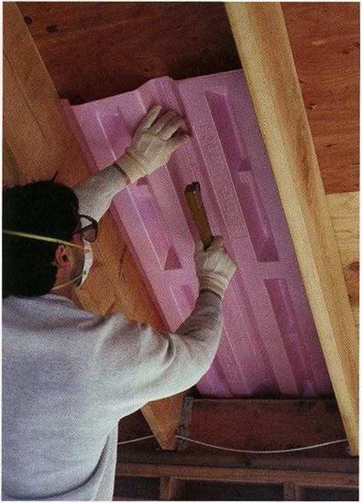
Подпись: BAFFLES PROVIDE SPACE FOR VENTILATION. On a flat roof or a cathedral ceiling, staple the baffles to the sheathing between framing members, then install the insulation. [Photo by Steve Culpepper, courtesy Fine Homebuilding magazine, ® The Taunton Press, Inc.)

say, 14 in. to 18 in. rather than just 12 in.—but it will save on heating and cooling costs for the life of the house.

Allow for ventilation space when insulating attics and ceilings

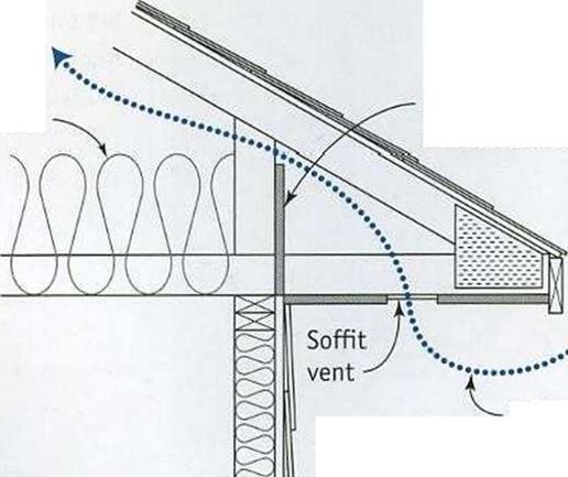
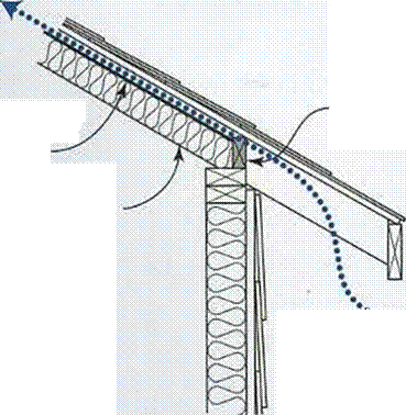
With insulation, the only time you can have too much of a good thing is when the ceiling or attic insulation blocks the roofs ventila­tion. As shown in the illustration on p. 204, there must be a clear pathway for air to move from the eaves to the ridge.

In the Charlotte house, we nailed OSB baffles in place on the walls between the roof trusses to prevent the attic insulation (blown-in cellulose) from spilling into the eaves and covering soffit vents. When a house has a cathe­dral ceiling, there is no attic space to fill with insulation. Instead, fiberglass batts must be installed between the rafters. Be especially careful not to block the ventilation space between the rafters. Various cardboard and foam baffles are available to provide venti­lation space and room for insulation accord­ing to the ceilings design. Staple the baffles between the rafters before installing the insu­lation (see the photo at right).

While you’re insulating the ceiling or attic, don’t forget the attic’s access cover or stairs. Rigid foam can be cut to insulate those open­ings. Using a compatible construction adhe­sive, glue several layers of foam on the top of the stairway or access hole cover (see the bot­tom left illustration on p. 130).

Safety on the Job WORKING WITH FIBERGLASS INSULATION

Подпись: ENSURING AIRFLOW ABOVE INSULATIONПодпись: STANDARD INSULATED CEILINGПодпись: InsulationПодпись: OSB or plywood baffles nailed between trussesПодпись:Safety on the Job WORKING WITH FIBERGLASS INSULATIONПодпись:Подпись: Cardboard or foam spacer (baffle)Подпись: CATHEDRAL CEILINGПодпись: InsulationПодпись: Vented blocks between raftersПодпись: Airflow-^Safety on the Job WORKING WITH FIBERGLASS INSULATIONПодпись:Insulating around obstacles

If all we had to do were to fill the stud and joist bays, then insulating would be easy. Problems often arise because of all the pipes, wires, light fixtures, and outlet boxes that are in walls and ceilings. For wires and pipes, cut a slice halfway through the batt and encase the pipe or wire in the insulation. Its important not to compress the batts. In cold regions,
make sure that you have insulation on the back of pipes (between the pipe and the exte­rior wall sheathing or siding) to keep them from freezing.

For electrical boxes, split the batt so that the insulation goes behind the box, as shown in the photos on the facing page. The front part of the batt can be neatly cut with a knife or scissors to fit around the box. Once the drywall is installed, you can use cover plates with a foam or rubber gasket over outlet and switch boxes to further reduce air passage.

Many recessed light fixtures generate so much heat that you have to leave a З-in., unin­sulated space around them. Don’t use these fixtures. Its much better to choose models that require no insulation gap. You can insu­late right up to and on top of those fixtures. Some states require that fixtures be airtight, too, so check with your building inspector.