Laying out the ridge board

Подпись: 2x10 ridge board

Rafters cover the joint between ridge sections

Ridge board ripped to width of barge rafter in overhang ‘

Подпись: Gable-end rafter 2×8 common rafter

Подпись:

every 1 б о. c. or 24 in. о. с. If more than one board will be used to make up the ridge, cut the boards so that each joint falls in the center of a pair of rafters. Be sure to align the layout of the ridge board to that of the joists so that the rafters and joists tie together at the plate line. If both are spaced 16 in. o. c., every rafter will tie into a joist (see the draw­ing on p. 142). If the joists are 1 б in. o. c. and the rafters are 24 in. o. c., a rafter will tie into every fourth joist.

Some builders like to let the ridge board extend out into the overhang and catch the ends of the barge rafters (see the drawing on the facing page). If you do this, rip the overhang part of the ridge board down to the actual size of the rafters because this section of the roof is exposed. Determine this length by mea­suring the face of the ridge plumb cut. For example, a 2×6 cut on an angle will be more than SV2 in. along the length of the cut.

Now comes the fun part. Nailing the rafters in place to the ridge board and to the wall plates and joists quickly gives the building frame a finished look. On most buildings, there is no need to pre­set the ridge at a predetermined height. Ridges are sort of like shoes. They go where they go. Setting rafters in place easily determines ridge height.

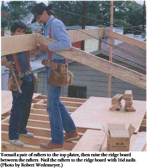
Begin by pulling up a straight, gable-end rafter. While one person holds the rafter at the ridge board, the other toenails the bottom end to the wall plate with 16d nails—one on each side of the rafter. Repeat this process with the opposing rafter. To hold them steady, tack a 1x brace from the rafters back to a joist.

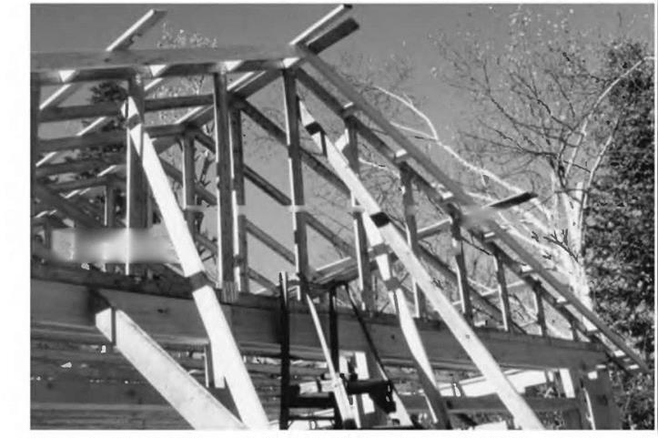
Now move to the opposite end of the first ridge section and toenail another rafter pair in the same way. Next, pull the ridge board up between the two pairs of rafters (see the photo above).

Drive two 16d nails straight through the ridge into the end of the first rafter, then angle two more through the ridge into the opposing rafter. I try not to nail in the top of any rafter, which helps me avoid dulling my sawblade later when I cut sheathing on the roof.

At this point, nail a 2×4 leg under the ridge board to a wall plate at both ends. These legs need to be the same length.

If they aren’t, it may mean that the walls are slightly out of parallel. Pull the nails out of the rafter pair at the top plate on the high end of the ridge and slide the rafters out a bit until the ridge rests on the 2x leg.

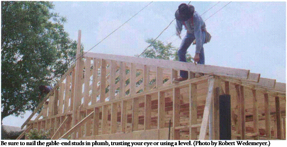
Подпись: Be sure to nail the gable-end studs in plumb, trusting your eye or using a level. (Photo by Robert Wedemeyer.)
Plumbing the ridge

Just as you did on the truss roof, nail a long 2×4 on edge to the side of the building. Push the end rafters against the upright and install a 2×4 sway brace extending from the top plate to the ridge board at a 45° angle. Nail it between the layout lines at the ridge board so that it won’t be in the way of a rafter.

After the initial ridge section is in place, raise the remaining sections in the same way, installing the minimum number of rafter pairs and support legs to hold them in place. At the opposite end, raise another 2x against the building and mark the ridge for length, plumb with the end of the building. Unless the ridge board runs out into the overhang, make the cut and nail in the second pair of straight, gable-end rafters.

With the entire ridge board in place, nail in the rest of the rafters and complete the roof frame. Nail each rafter into the ridge board with two 16d nails, then nail
rafters to the ceiling joists with three 16d nails. The rafter should be toenailed to the wall with two 16d nails. Nail in several rafters on one side and then switch and do the same on the other side. Switch back and forth, or you may get too much weight on one side and cause the ridge board to bow.

Characteristics of the SMA Course

Constituent materials, design, production, and placement of a stone matrix asphalt (SMA) mixture were discussed in previous chapters. It would not make sense to spend this much time discussing the mix if SMA courses had not been characterized with many strong points. Conversely, it should be openly admitted that it is not a perfect mixture, and it also has a couple of run-of-the-mill or slightly poorer proper­ties among some very remarkable and even outstanding ones. In any case, its lack of perfection does not affect the final appraisal of SMA as a very useful material for pavements. After all, the rapid increase in SMA applications all over the world has not been exclusively brought about by fashion.

Next, the following operation and maintenance properties of SMA courses will be elaborated on

• Resistance to permanent deformation

• Crack resistance

• Fatigue limit

• Antinoise properties

• Antispray and antiglare properties

• Antiskid properties

• Durability

• Permeability

• Impact on fuel consumption while driving

• Economic effectiveness

This discussion will begin with a short comparison of SMA and other competi­tive mixtures that are used for wearing courses. Table 12.1 shows a comparison of selected properties of SMA, open graded asphalt, ultra-thin friction courses, and continuous graded asphalt mixtures (Pretorius et al., 2004). One can see from this table that SMA mixtures generally compare very favorably with the other types of mixtures but that SMA may not be the best choice for all applications.

OVERDOSAGE OF AN ANTISTRIP ADDITIVE

It happens occasionally that an additive dosing system does not work correctly. When that happens, there is either too much or too little antistrip additive in the mixture. Its deficiency does not directly affect the quality of the mixture during production or placement. Effects may appear in the form of a lower durability of the course under traffic. However, an excess of the antistrip additive can manifest itself in an imme­diate and direct impact on the quality of the mixture. Usually the antistrip additive overdosage may be identified while still in the batching plant because of the charac­teristic (i. e., unpleasant) smell of the mixture.* The overdosed mixture distinguishes itself by having a very high workability both in the paver and under rollers, to such an extent that its further compaction is possible for up to a couple of days after place­ment (i. e., it is still deformable under rollers). Putting such a pavement into operation results in its rapid rutting. Another effect of increased workability of the mixture while rolling is the risk of fat spots or areas with a closed structure.

Depends on the type of adhesive agent used (mainly concerns some fatty amines).

Sma susceptibility to polishing

Although susceptibility to polishing is not a problem at the construction stage but a result of an earlier decision, greater pavement slipperiness becomes apparent after some time of pavement operation. The source of this problem is at the design stage of an SMA composition. The proper selection of an aggregates for a mixture and the level of designed air voids content are crucial.

image143

FIGuRE 11.34 Mastic squeezed-out of SMA in wheel paths during trafficking of pave­ment. (Photo courtesy of Krzysztof Blazejowski.)

image144

FIGURE 11.35 Polished SMA surface after 3 years of operation. (Photo courtesy of Krzysztof Blazejowski.)

We may define the expected scope of an aggregate’s polishing resistance for wearing courses through the selection of the polished stone value (PSV) category. PSV checking consists of testing the microtexture loss of aggregate grains under standardized conditions according to EN 1097-8. Figure 11.35 shows the effect of polishing a pavement after 3 years of traffic. This pavement, except for polished grains, shows no other damage.

Installing a Granite Countertop

Once you’ve looked at granite samples and narrowed your choices to a few varieties, consult the fabricator—the company that will be cutting and installing your stone.

For example, if you choose a granite with large crystals, joints between sections may be more obvious than those between finely grained stone. Besides, some richly figured stones are more likely to crack or spall when subjected to everyday use. A fabricator’s practical concerns can be a good counterpoint to a kitchen designer’s artier point of view. In any event, cabinets and the plywood substrate must be installed before measurements for a stone countertop can be made.

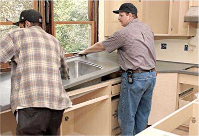
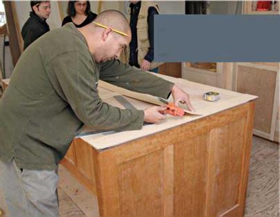
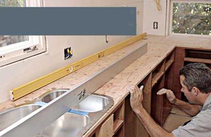
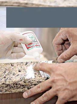
1. Подпись: sink to hundreds for a custom-made, 16-gauge commercial-grade sink with multiple bowls. ► Enameled cast-iron or enameled-steel sinks are available in numerous colors and provide a classic look that works in modern and traditional kitchens. Enameled sinks have a hard finish; but the enamel can chip, making the metal substrate likely to rust. Abrasive Подпись: 2. After ensuring that the substrate is flat, installers typically lift the slabs, stand them on edge, and carefully lower them into position to test clearances, cutouts, overhangs, and so on.

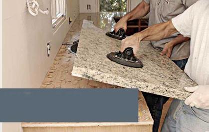
Подпись: 4. After caulking the undermount sink with silicone, installers set the slab on the epoxy grid. To avoid spreading the epoxy too thin, installers don’t slide the stone in place—they lift and lower it as close to the final position as possible. Suction-cup handles help. Подпись: 5. After leveling the slabs, pros ensure that the joint are flush by sliding a razor blade back and forth acro; them. If one side is higher, the razor blade clicks as it hits a high point or falls from a high point to a low one. More sensitive than a fingertip!
Подпись: . .УЖ

An experienced installer takes nothing for granted and will scrutinize substrates for high and low spots before anything else. However, it’s a general contractor’s responsibility to make the substrates flat—not the counter installer’s.

Подпись: cleaners quickly dull enamel finishes. Cast iron is so heavy that it takes two people to install it and so hard that it’s monstrously difficult to drill if you need an additional hole for a water filter or some other accessory. Delicate dishes or glasses dropped on it are doomed. Cost: $200 to $500+ for cast iron; slightly less for steel.image663image664"Подпись: 3. If the dry-fit is acceptable, installers set the slabs aside and apply a grid of epoxy blobs, which adhere the stone to the substrate and act as a support. Epoxy typically takes 48 hours to set fully. To keep the stone from moving while the epoxy grid cures, installers use a smaller amount of a different fast-acting epoxy.image665Подпись:Solid-surface sinks are usually manufactured from the same material as the counter and glued (chemically bonded) to the underside of the counter for a seamless, leakproof joint that won’t catch food scraps.

As with counters, solid-surface sinks are stain resistant, nonporous, and easy to clean.

And you can sand them smooth if they get gouged or scorched.

For aesthetic reasons, solid – surface sinks are rarely

installed with dissimilar Solid-surface sinks are chemically

counters; although a near-cousin, quartz bonded to a counter of the same

composite, looks enough like granite that it material, creating a leak-free seam.

contrasts well with other counter materials.

Cost: $200 to $750 for a solid-surface sink.

► Acrylic sinks have a lot going for them.

They’re lightweight, nonporous, and easy to keep clean. They’re also stain and crack resis­tant, available in many colors, and reasonably priced. However, compared to solid-surface materials, acrylics are relatively soft, so they should be cleaned with nonabrasive cleaners.

They can be damaged by extreme heat and may be incompatible with petroleum-based cleaners and caulks. Cost: $150 to $300.

Mounting style. There are a number of mount­ing styles, although almost all require a bead of sealant along their perimeter to keep water from getting under the sink rim. Mounting styles include self-rimming, undermount, integral, flush mount, and separate rim.

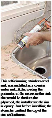
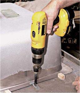
► Self-rimming sinks (see p. 320) are popular and easy to install because the sink rim sits on the countertop—after you’ve applied a bead of silicone sealant around the perimeter of the sink cutout. Heavier sinks, such as cast iron, are held in place by the adhesion of the sealant and the weight of the sink; whereas lighter sinks, such as stainless steel, require clips on the underside of the counter. When a self-rimming sink is set under a countertop, as shown at left, it may be called a counter-under sink.

► Undermount sinks are placed under a counter whose sink opening must be finished because it isn’t covered by the sink rim.

Counters with undermount sinks are easy to keep clean because there’s no rim to block food scraps; just sweep them into the sink.

image666Typically, clips attach the rim to the underside of the counter; many contractors also add framing inside the sink cabinet to support the sink when it’s filled with water.

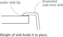
I Sink-Mounting Details

Подпись:
Подпись: PROTIP If you're cutting a finish surface such as plastic laminate, cover the metal shoe (base) of your jigsaw with masking tape to keep the shoe from scratching the countertop. llll

image667

SELF-RIMMING SINK Sealant

UNDERMOUNT SINK

~1~ґ

Counter overhangs sink.

гг

Sealant

Sink clip or wood frame supports sink.

Leakproof

INTEGRAL SINK

seam

image668

Counter and sink are same material, bonded chemically.

► Integral sinks are bonded to a counter of the same material, creating a seamless, leak – free joint. Integral sinks are common to solid – surface and quartz-composite counters.

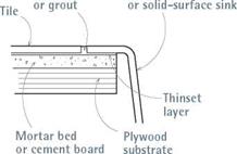
► Flush-mount (tile-edge) sinks, have a rim the same thickness as the tile layer, when both rest atop a thin-set mortar bed. Such sinks are typically enameled steel or cast iron. You can fill the tile-sink rim joint with grout or silicone seal­ant, but acrylic latex sanded caulk has the best qualities of both and comes in several colors.

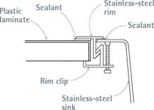
► Separate-rim sinks are usually stainless steel and employ a separate stainless-steel rim to cover the joint between the small sink rim and the edge of the counter. To prevent leaks, you must seal both the sink-side and the counter-side of the rim.

INSTALLING A KITCHEN SINK

Because self-rimming sinks are the most com­mon, this section focuses on their installation. If your sink has another mounting device, follow the manufacturer’s installation instructions.

FLUSH-MOUNT OR TILE-EDGE SINK

Sanded caulk Enameled cast-iron

image669

SEPARATE-RIM SINK

image670

Lay out the opening. Mark the sink cutout (opening) on the counter or the plywood sub­strate. Most sinks come with a paper template of the cutout; if yours doesn’t, make one of card­board. To do that, turn the sink upside-down onto the cardboard and, with a felt marker, trace its outline. Next, use a yardstick to draw a second outline, M in. inside the first, on the cardboard. Sink rims are typically 54 in. wide, so the inner line represents the size of the cutout, and the outer line shows how much clearance the sink rim needs. Position the cutout template on the counter so there’s clearance on all sides; then use a felt marker to trace around the template.

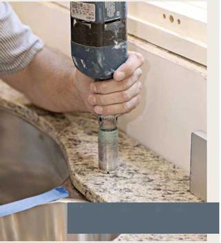
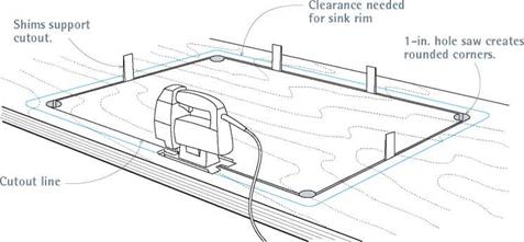
Cut the opening. Drill a hole at each corner of the cutout for your jigsaw blade; if you use a hole saw to drill the corners, its arc should match the rounded corners of the sink body. As you cut each side of the sink opening, stop just short of the cor­ner hole. Then drive a shim into the saw kerf—from the underside of the counter—to keep the cutout section from falling. (A wood shingle is a perfect shim.) With a few shims in place, finish cutting

image671
Подпись: Because sink rims are typically 3/4 in. wide, create cardboard templates to show both the clearance needed for the rim and the cutout line needed for the sink body.

Подпись:

I Cutting Out a Sink Opening

to the comer holes and lift the cutout section, using the corner holes as finger holds. Use a wood rasp to smooth rough cut-lines or splinters.

Install the sink. Wearing heavy work gloves, put your fingers in the sink drain and faucet holes, lift the sink, and lower it into the cutout. Two people should lift and set the sink if it’s cast iron; put wood scraps around the cutout to set the sink on so it doesn’t crush your fingertips. Check the sink’s fit in the cutout—look under the counter as well—before lifting the sink out. Trim the cutout as needed. Then mount the drain basket, faucet
assembly, and accessories to the sink; they’re harder to attach once the sink is in place. To cushion the sink hardware and create a water­tight seal, use the flexible seals or plastic plates provided by the manufacturer. If the unit has a hollow body, put a bead of plumber’s putty beneath its lip. Dont do this ifthe countertop is stone; the oil in the putty may stain the stone. Silicone will work, too, but it can make the faucet difficult to remove if you decide to replace it.

Just before installing the sink in its opening,
apply a cushion of sealant for the sink rim to rest

image673

Here an undermount sink is being clip mounted to the underside of a solid-surface counter…


image674

… and then lifted as a unit and placed atop a base cabinet. Supplemental plywood frames inside the cabinet will also support the sink rim.


ORDERING COUNTERTOPS

Once you’ve identified several reputable coun­tertop shops in your area, get bids. For your protection, develop detailed floor plans and, as you proceed, put everything in writing. That way, you’ll be sure that quotes from different shops reflect similar details, deadlines, and so on. The following guidelines are adapted, with permission, from Sullivan Counter Tops, Inc. (visit www. sullivancountertops. com).

Visit suppliers in your area. Look at counter­tops in several different showrooms, and discuss your options with the salespeople. Share any information—samples of wall paint or cabinet finishes, magazine ads showing counter surfaces, photos of sinks or sink fixtures—that will clarify the style and look you’re after. A salesperson’s willingness to spend time and answer questions says a lot about a supplier.

Get bids. Provide a floor plan, drawing, or sketch to the countertop suppliers, and ask each to gen­erate a written bid. The bid should also specify a completion date, terms of payment, and the scope

of the installation. In most cases, quoted prices will not include plumbing, electrical work, or adjustments to the cabinets such as sink cutouts and leveling plywood substrates. Tearing out old countertops is usually extra, too. Based on bids and supplier reputations, choose a supplier.

Schedule the job. Most installations require two visits from the supplier: the "measure date” and the "install date.” It’s difficult to pinpoint a meas­ure date until the cabinets are installed, but in general, 2 weeks’ to 4 weeks’ notice should be enough. Typically, solid-surface (such as Corian) and plastic-laminate countertops require about 1 week between the measure date and the install date. Quartz-composite countertops (such as Zodiaq) require about 2 weeks. Most countertop suppliers will allow you to change the installation time without penalty, provided you give them enough notice.

Be prepared for meetings. The measure date is your last chance to give input on details such as underlayment issues, color, edge treatment, and splash detail. Whatever you finally decide on, get it in writing. During this meeting, the supplier will review job site conditions, so the general contractor should be there, too.

Important prerequisites

► Cabinets must be set before the job can be measured. In other words, the cabinets must be screwed together and screwed to the walls, not just pushed into place. The cabinets cannot be moved even И in. after the countertop supplier has measured because countertops are fabricated to close tolerances.

► Cabinets must be set level. As general rule, cabinets must be set on a level plane within % in. over a 10-ft. length. Such stringent requirements are a concern not only to installers but also, in some cases, to manu­facturers as a condition of warranty.

► All appliances and sinks should be on the job site at the time of the measure. The fitting of sinks and appliances is often critically close. Design or construction issues that could cause problems or delay the installation should be resolved on the measure date. If the sinks and appliances are on site, the supplier can inspect them. If there’s a defect, damage, or, say, a sink rim that won’t fit the countertop, you’ll need time to replace the item before installation.

Kitchen Sinks

Because a kitchen is one the most-used rooms in the house, do a little research before choosing its most-used fixture.

CHOOSING A KITCHEN SINK

Keep four criteria in mind when considering sinks: size and number of bowls, sink-hole compatibility with faucets and accessories, mate­rials, and mounting styles.

Size and number of bowls. Sinks are available in dozens of sizes and shapes. For the record, a 22-in. by 33-in. two-bowl unit is the most popular, perhaps because it fits neatly into “standard” sink cabinets 24 in. deep by 36 in. long. Two bowls allow you to prep food in one, and put used bowls and pots in the other, during the mad dash to din­ner. Typically, there’s a garbage disposer on one side. If you’ve got a dishwasher and don’t need to wash dishes in the sink, a large single-bowl sink is best suited to washing pots and pans; 10 in. deep is optimal. If you’ve got plenty of counter space and two family members like to cook, install two separate sinks. By the way, three-bowl sinks (45 in. wide) are overkill for most home kitchens.

Most sinks have one to four holes. Typically the spout and faucet handles take up three of those holes, but some single-lever faucets require only one hole. Filling an extra hole is generally not a problem, what with soap dispensers, hot-water dispensers, spray units, filtered-water dispensers, and so on to choose from. Incompatibility more often occurs when a faucet assembly’s valve stems have a different spacing than the holes in the sink. Always measure the sink and the faucet assembly to be sure. Likewise, if the sink is undermounted, an installer must drill holes into a countertop, making sure they have the same spacing as the faucet to be installed.

Materials. Sink materials include many of those used for countertops. You can use almost any­thing that will hold water, but ideally it should be


light enough to install without breaking your back, easy to clean, durable, moderately priced, heat resistant, and stain resistant. Few materials fill the bill as well as stainless steel.

► Stainless-steel sinks represent roughly three-quarters of all kitchen installations. Typically, they have a brushed or polished finish; brushed finishes are easier to maintain


ORDERING COUNTERTOPS

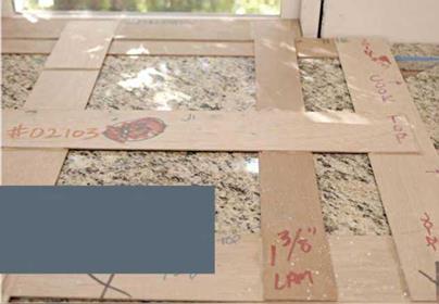
Templates are useful for transferring accurate measurements to any sheet material or flat surface, whether it’s a piece of drywall that needs to be notched beneath an exposed stair or a new door that must be fit to an old, out-of-square door frame. When the going gets rough, the pros make templates. Nowhere is this truer than when those large sheets are granite slabs. Often, countertop suppliers create templates during the "measure date" described in "Ordering Countertops," on the facing page.


ORDERING COUNTERTOPS

image656

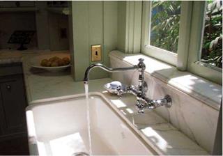
This enameled cast-iron farmhouse sink is big enough to rinse as large a turkey as you can lift. The faucet’s spout swings out of the way for complete access to the sink. (Fixture available from www. bathsfromthepast. com.)


JHS> AWrt ■ЗТІ ^ETdli/iiv 6^ Г4>т^-


The more complex the site conditions or cutouts, the more information the template contains. This small section notes the type of granite, edge bevels, and thickness and the location of the sink cutout. The template’s back edge registers to the window width.


image657image658

image659image660image661image662because water spots don’t show as conspic­uously. A sink’s gauge (thickness) is the real differentiator. Thicker gauges (16 gauge to 18 gauge) are harder to flex and dent and are quieter to use; whereas thinner gauges (20 gauge to 22 gauge) are less expensive, less durable, and more inclined to stain. Cost: This can range widely, from $40 for a 22-gauge single-bowl
In-Situ Results

The deterioration of strength, stiffness and resistance to the development of per­manent deformation, or the reduction in pavement life, with increasing moisture levels is a common observation. Trial pavement studies in which the water content of the construction has been changed and reduced performance observed are quite numerous. In recent years work in Finland has been reported by Korkiala-Tanttu and Dawson (2007) showing the much faster rutting of a test pavement with a high water table than one in which it was lower. In an earlier study by accelerated trafficking, Vuong et al. (1994) found that the life of a crushed-rock base was very dependent on the degree of saturation in the aggregate base course. Assuming a water content for optimal behaviour, then a 5% change increase in relative water content could lead to a 400% reduction in pavement life. Sharp et al. (1999) reported significant deterioration of in-situ moduli values at an accelerated pavement testing site in lat – eritic gravel bases and sub-bases upon wetting (or improvement on drying) by more than a factor of 2. The silty sand subgrade at the test site also changed stiffness to a similar degree.

Thus site studies broadly support the laboratory and theoretical work reported elsewhere in this book. As an example of a particular study of the effects of moisture change on bearing capacity, the following case record is instructive.

Plank and Beam Roofing

“Plank and beam” roofing consists of planks — often tongue-in-groove — supported from below by exposed beams, or rafters. This is the system we used at Log End Cottage, Log End Cave, and Earthwood, and it is my favorite roof support system for three reasons:

i. We like the aesthetic appeal of exposed beams, with light- colored V-joint tongue-in­groove planking above them.

Fig. 4.46: The trusses are temporarily stored upside down, straddling the sidewalls.


image90

image91Подпись: 2. Plank and beam roofing is strong. For example, two-by-six tongue-in- groove planking — on four-foot centers — will support a 185 PSF (pounds per square foot) earth roof load, providing that the beam framework is engineered correctly. With conventional roof loads, planking spans of six feet and even eight feet are possible. Fig. 4.52 shows a strong homemade truss system, with the tension and compression web members sandwichedFig. 4.47: Chris started with the second truss from the end, well braced to the ground. The first and last trusses, called the gable trusses, have overhangs built into them, which makes them more difficult to deal with. After all the other trusses are braced firmly in place, the two gable trusses are installed. The 24-inch centers are already marked on the sidewall girts, and each truss is given exactly the same overhang at each end. Once the overhang has been determined at both ends of the first truss, the others can be marked exactly the same. Before the crew arrived, Chris made sure that his sidewalls were straight and well-braced from the sides.

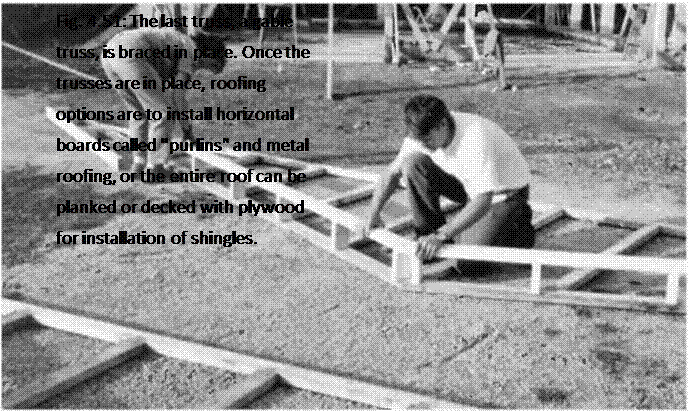
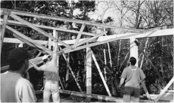
Fig. 4.48: With a long two-by-four fastened near the top of the truss with a pivot nail, Chris raises the point of the truss to vertical. The two helpers set it on the 24-inch center marks, and communicate with each other about the overhang. Toenails fasten the trusses to the doubled two-by – eight girts, but the trusses are also temporarily cross-braced to each other, so that they don’t go down like so many dominoes.


Fig. 4.49: The third truss is raised.


image92

between doubled top and bottom chords. Note the wide planking spans and the attractive heavy metal truss plates.

Incidentally, building up a frame with bolted timbers, as in this picture, is another great framing system, but beyond the scope of this book. Called the Walter Segal timber frame method, it has become very popular with owner-builders in the United Kingdom. The method is covered very well in Out of the Woods: Ecological Designs for Timber Frame Housing, listed in the Bibliography.

Подпись:

image93 Подпись: Fig. 4.50: Chris and his wife, Kat, make and install the "ladder” to the two gable trusses, to provide an overhang. Note that the gable trusses have lots of vertical members, instead of the angled tension and compression chords. With the ladder and number of vertical members, these trusses are probably about twice as heavy as the others. They can be installed after the other trusses are well- braced to each other.

image943. Plank and beam roofing is easy to do. Nailing goes quickly because normally, the installer is nailing into fairly wide beams. You’ve almost got to try to miss the beam to do so.

Once the plank-and-beam roof is engineered, installation is as easy as installing the rafters, then nailing down the planking.

Slip Base Designs

Slip base designs for multiple sign supports are usually of horizontal design as shown in Figs. 7.23 and 7.26. Horizontal slip bases, when used in multiple-sign-support systems, operate satisfactorily when impacted from only one direction. Horizontal slip bases should not, therefore, be used for multiple sign supports where there is a high probability of impacts from more than one direction. In Fig. 7.26, the keeper plate prevents the bolts from “walking” out of the assembly as a result of wind vibration (Art. 7.4). The washers should separate the upper and lower slip plates by at least И in (3 mm), but not more than И in (6 mm), to prevent mating of the surfaces and possible binding due to friction. Proper size washers must also be used under the nut and bolt head to prevent the washers from deforming into the slots of the slip plates and binding the mechanism.

A typical concrete foundation detail is shown in Fig. 7.50, and specifications for the anchor piece of slip base designs are presented in Table 7.14. Notice that the foun­dation design includes eight reinforcing bars spaced around the anchor piece. This is a typical installation which is effective in maintaining the integrity of the foundation

a BARS V

DRILLED SHAFT (CONCRETE)

FIGURE 7.50 Horizontal base and concrete foundation detail.

under vibrations resulting from environmental loads. State specifications should be consulted to determine if local requirements deviate from details shown in Fig. 7.50.

Proper functioning of the slip base requires correct selection of bolt size and torque. Table 7.15 gives typical design specifications for large roadside sign slip bases and concrete foundations.

An omnidirectional triangular base, mounted in standard soil with three 2V2-in X 21/2-in (64-mm X 64-mm) perforated steel tube supports located within a 7-ft (2100-mm) radius, has been approved for use [49].

Protection from Decay

Moisture and warm air are catalysts of fungus, which causes dry rot that can destroy a building.

In addition to calling for ventilation to control moisture, the code also requires decay-resistant wood wherever moisture can come in contact with structural wood. Some areas of the country are more conducive to decay than others. The code requires naturally durable wood or preservative-treated wood in the following situations:

• Wood joist or the bottom of the wood floor structure if less than 18" from exposed ground. (See “Joists & Girder Protection" illustration.)

• Wood girders if closer than 12" from exposed ground.

• Wall plates, mudsills, or sheathing that rest on concrete or masonry exterior walls less than 8" from exposed ground. (See “Exterior Wall Decay Protection" illustration.)

• Sills or sleepers that rest on a concrete or masonry slab in direct contact with the ground, unless separated from the slab by an impervious moisture barrier. (See “Decay Protection from Slab" illustration later in this chapter.)

• The ends of wood girders entering exterior masonry or concrete walls having less than %" clearance on tops, sides, and ends. (See “Ends of Girders in Masonry or Concrete" illustration.)

• Posts or columns that support permanent structures and are themselves supported by a masonry concrete slab or footing in direct contact with the ground. (See “Post and Column Decay-Resistant Wood" illustration.)

Space on top, sides, and end must be V2" or girder needs to be of decay – resistant wood.

Nailing

Nailing is one of the most important parts of framing. Table 2304.9.1, Fastening Schedule (see IBC Nailing Table), is taken directly from the IBC 2009. The table shows use of alternate nails. The 3” x 0.131” nail is the most common nail gun nail used for framing.

TABLE 2304.9.1 FASTENING SCHEDULE

CONNECTION

FASTENINGam

LOCATION

1. Joist to sill or girder

3 – 8d common (2’/2 0.131 ) 3 – 3 0.131 nails 3 – 3 14 gage staples

toenail

2. Bridging to joist

2 – 8d common (2’/2 X 0.131 ) 2 – 3 0.131 nails 2 – 3 14 gage staples

toenail each end

3. 1 6 subfloor or less to each joist

2 – 8d common (2’/2 0.131 )

face nail

4. Wider than 1 6 subfloorto each joist

3 – 8d common (2’/2 0.131 )

face nail

5. 2 subfloor to joist or girder

2 – 16d common (3’/2 0.162 )

blind and face nail

6. Sole plate to joist or blocking

Sole plate to joist or blocking at braced

16d (3V2 0.135 ) at 16 o. c. 3 0.131 nails at 8 o. c.

3 14 gage staples at 12 o. c.

3 – 16d (3V2 0.135 ) at 16

typical face nail

wall panel

4 – 3 0.131 nails at 16 4 – 3 14 gage staples per 16

braced wall panels

7. Top plate to stud

2 – 16d common (3V2 0.162 )

3 – 3 0.131 nails 3 – 3 14 gage staples

end nail

8. Stud to sole plate

4 – 8d common (2’/2 0.131 )

4 – 3 0.131 nails 3 – 3 14 gage staples

2 – 16d common (3V2 0.162 )

3 – 3 0.131 nails 3 – 3 14 gage staples

toenail end nail

9. Double studs

16d (3V2 0.135 ) at 24 o. c. 3 0.131 nail at 8 o. c.

3 14 gage staple at 8 o. c.

face nail

10. Double top plates Double top plates

16d (3V2 0.135 ) at 16 o. c. 3 0.131 nail at 12 o. c.

3 14 gage staple at 12 o. c.

8-16d common (3V2 0.162 ) 12-3 0.131 nails 12-3 14 gage staples

typical face nail lap splice

11. Blocking between joists or rafters to top plate

3 – 8d common (2’/2 0.131 ) 3 – 3 0.131 nails 3 – 3 14 gage staples

toenail

12. Rim joist to top plate

8d (2V2 0.131 ) at 6 o. c. 3 0.131 nail at 6 o. c.

3 14 gage staple at 6 o. c.

toenail

13. Top plates, laps and intersections

2 – 16d common (3V2 0.162 )

3 – 3 0.131 nails 3 -3 14 gage staples

face nail

14. Continuous header, two pieces

16d common (3’/2 0.162 )

16 o. c. along edge

15. Ceiling joists to plate

3 – 8d common (2’/2 0.131 ) 5 – 3 0.131 nails 5 – 3 14 gage staples

toenail

16. Continuous header to stud

4 – 8d common (2’/2 0.131 )

toenail

(continued)

Source: The International Building Code, copyright © 2009, with permission from the International Code Council, Inc.

For SI: 1 inch = 25.4 mm.

a. Common or box nails are permitted to be used except where otherwise stated.

b. Nails spaced at 6 inches on center at edges, 12 inches at intermediate supports except 6 inches at supports where spans are 48 inches or more. For nailing of wood structural panel and particleboard diaphragms and shear walls, refer to Section 2305. Nails for wall sheathing are permitted to be common, box or casing.

c. Common or deformed shank (6d – 2 0.113 ; 8d – 2V2 0.131 ; 10d – 3 0.148 ).

d. Common (6d – 2 0.113 ; 8d – 2V2 0.131 ; 10d – 3 0.148 ).

e. Deformed shank (6d – 2 0.113 ; 8d – 2V2 0.131 ; 10d – 3 0.148 ).

f. Corrosion-resistant siding (6d – 17/8 0.106 ; 8d – 23/8 0.128 ) or casing (6d – 2 0.099 ; 8d – 2V2 0.113 ) nail.

g. Fasteners spaced 3 inches on center at exterior edges and 6 inches on center at intermediate supports, when used as structural sheathing. Spacing shall be 6 inches

on center on the edges and 12 inches on center at intermediate supports for nonstructural applications.

h. Corrosion-resistant roofing nails with 7/16 – inch-diameter head and 11/2-inch length for 1/2-inch sheathing and 1 3/4-inch length for 25/32-inch sheathing.

i. Corrosion-resistantstapleswithnominal7/16-inchcrownand 11/8-inchlengthfor 1/2-inchsheathingand 1 1/2-inchlengthfor25/32-inchsheathing. Panelsupportsat 16 inches (20 inches if strength axis in the long direction of the panel, unless otherwise marked).

j. Casing (1V2 0.080 ) or finish (1V2 0.072 ) nails spaced 6 inches on panel edges, 12 inches at intermediate supports.

k. Panel supports at 24 inches. Casing or finish nails spaced 6 inches on panel edges, 12 inches at intermediate supports.

l. For roof sheathing applications, 8d nails (2V2 0.113 ) are the minimum required for wood structural panels.

m. Staples shall have a minimum crown width of 7/16 inch.

n. For roof sheathing applications, fasteners spaced 4 inches on center at edges, 8 inches at intermediate supports.

o. Fasteners spaced 4 inches on center at edges, 8 inches at intermediate supports for subfloor and wall sheathing and 3 inches on center at edges, 6 inches at interme­diate supports for roof sheathing.

p. Fasteners spaced 4 inches on center at edges, 8 inches at intermediate supports.

Source: The International Building Code, copyright © 2009, with permission from the International Code Council, Inc.

Termite Protection

Framers in many areas of the country have to be concerned about protection against termites. Pressure preservative-treated wood, naturally termite-resistant wood, or physical barriers can be used to prevent termite damage. The following map shows termite infestation probability by region.

Termite Infestation Probability

Conclusion

An important part of your job as a lead framer is being aware of the building codes that apply to framing in your part of the country. You should be aware of how to use the code and of any revisions to those codes. Although locating information you need in the code books is often the hardest part of using the codes, the “Framing Index" at the beginning of this chapter should make this easier for you. It’s a good feeling to know that you have framed a building the way it’s specified according to code.