Posted by admin on 22/ 11/ 15
Microwave Ovens
Microwave ovens emit high electromagnetic fields (EMFs). These ovens are designed to heat food by creating enough microwave energy to vibrate molecules in the food until heat is produced. When microwave ovens are in use, magnetic fields extend out as far as 12 feet. The actual microwaves produced during operation are supposed to be contained in the oven by internal shielding, but leaks can occur. If you decide to use a microwave oven, the following suggestions will make using it safer:
• Maintain a distance of four to 12 feet from the microwave oven while it is in use. This is especially important for children, who might enjoy watching the food as it is cooking.
• Have your appliance professionally checked for microwave leakage on an annual basis. You can check it yourself on a more frequent basis with a less precise do-it – yourself tester. (One is available through Professional Equipment, a mail order catalog.) Any detectedleakage is unacceptable. Microwave leakage standards in the US are much less stringent than in some parts of Europe. Unfortunately, differences in the power supply prevent the use of European microwave ovens in North America.
• Do not use a microwave that appears to be malfunctioning. Signs of this would include sparks flying, funny noises, fires, or the unit turning on or cycling when the door is open. If any of these occur, evacuate the area immediately. Do not take time to try to unplug the unit. Instead, shut off the circuit breaker to the microwave. If you do not know which one it is, shut them all off. Only then is it safe to return to the room to unplug the microwave oven.
• The shielding on a microwave is delicate. A very small amount of damage can cause a complete shielding failure. Even a paper towel stuck in the door is enough to cause the microwave shielding to fail.
• Do not microwave food in plastic containers. Chemicals from the plastic can leach into the food. Some of these chemicals are known to disrupt the endocrine system.
Trash Compactors
Trash compactors are now commonplace in new homes. They can be convenient, but they can also be difficult to dean. When choosing a trash compactor, examine it carefully to be sure you will be able to reach into it easily for cleaning. Verify that accidental liquid spills inside the unit will be contained and not run under or behind the unit. You may want to have the trash compactor installed in such a way that it can be easily removed for cleaning.
Some trash compactors come with a deodorizer chamber. With the exceptions of baking soda and zeolyte, most deodorizers contain phenols, formaldehyde, or paradichloroben – zene, all of which should be avoided.
Posted by admin on 22/ 11/ 15
Available computer programs accurately design lighting systems using photometric curves and data for various fixtures. Some programs allow the user to input items such as trees and other physical barriers that may interfere with the output from the light fixtures. These programs will calculate luminance, illuminance, and glare. Dirt and maintenance factors that depend on the environment of the fixture location and the type of fixture are also used in the calculations. Some of the programs are easy to operate and very user friendly whereas some require much more detail. Computer-generated drawing files can be imported into the program, thus allowing the use of available site and roadway plans without the necessity of compiling a new drawing. Lighting manufacturers have made photometric data available from their company websites, and this information can be imported into the software program. After the design is completed, some programs are capable of providing a three-dimensional rendering showing a pictorial view of the proposed area. With the ease of obtaining all required input information, a lighting designer can experiment with the use of various fixture styles, wattages, and photometric patterns. Thus, the designer can obtain maximum light levels with consideration of both initial installation costs and annual operating costs, which include energy costs and maintenance items such as cleaning and lamp and ballast replacement.
Posted by admin on 22/ 11/ 15
Are you aware of the Unified Numbering System (UNS)? This is a system that is meant to correlate the many metal alloy numbering systems that are being used in our country. I could go into a long discussion on this, but I believe that a simple table will give you enough information for now. Figure 11.1 shows you the various categories of alloys. If you look to the left of the table, you will see letters. The letters are the beginning for understanding types of alloys. For example, if a rating starts with the letter C, it is referring to copper. Seeing a letter F at the beginning of a rating indicates cast-iron.
  METRIC SIZES METRIC SIZES
 Metric sizes are common in many places of the world. Plumbers in the United States still work primarily with customary measurements in terms of inches. However, you may find times when metric equivalents are useful. For this reason, I’m providing Figure 11.2 Metric sizes are common in many places of the world. Plumbers in the United States still work primarily with customary measurements in terms of inches. However, you may find times when metric equivalents are useful. For this reason, I’m providing Figure 11.2
201
|
The first letter (followed by five digits)
|
Alloy category (assigned to date)
|
|
Axxxxx
|
Aluminum and its alloys
|
|
Cxxxxx
|
Copper and its alloys
|
|
Exxxxx
|
Rare-earth metals, and similar metals and alloys
|
|
Fxxxxx
|
Cast irons
|
|
Gxxxxx
|
AISI and SAE carbon and alloy steels
|
|
Hxxxxx
|
AISI and SAE H-steels
|
|
Jxxxxx
|
Cast steels (except tool steels)
|
|
Kxxxxx
|
Miscellaneous steels and ferrous alloys
|
|
Lxxxxx
|
Low-melting metals and their alloys
|
|
Mxxxxx
|
Miscellaneous nonferrous metals and their alloys
|
|
Nxxxxx
|
Nickel and its alloys
|
|
Pxxxxx
|
Precious metals and their alloys
|
|
Rxxxxx
|
Reactive and refractory metals and their alloys
|
|
Sxxxxx
|
Heat – and corrosion-resistant steels (including stainless), valve steels and iron-based “superalloys”
|
|
Txxxxx
|
Tool steels (wrought and cast)
|
|
Wxxxxx
|
Welding filler metals
|
|
Zxxxxx
|
Zinc and its alloys
|
FIGURE 11.1 ■ UNS metal family designations. (Courtesy of McGraw-Hill) for your use in comparing common measurements from the United States to metric measurements.
THREADED RODS
Threaded rods are often used to hang various types of pipe. If the size of the threaded pipe is too small in diameter and in its ability to support a proper amount of weight, the use of the rod can be very destructive. If you have a need to choose threaded rod for hanging pipe, you should find the information in Figures 11.3 and 11.4 very helpful.
Posted by admin on 22/ 11/ 15
The Arabs came not only from North Africa, but also from Arabia, Syria, Iraq, Yemen, and Egypt. In 711 they conquered Spain, a country that had been occupied by the Visigoths since the fall of the Roman Empire. They brought with them all the Oriental technologies for water management: the ancient shaduf the bucket chain or saqqya, the noria, and qanats. The Arabs preferred developments of more modest scale in the Mesopotamian tradition compared to the grand Roman hydraulic works. The great Roman dam-reservoirs like those of Proserpina and Cornalvo were apparently not brought back into service.
42
It is thought that the oldest Arab project is an overflow dam built at Cordova, the capital of the Umeyyade caliphate. Its total length of425 m exceeds the width of the river Guadalquivir, since it comprises multiple independent segments to increase the effective length of the weir and thus to limit the rise in water level during floods. We have seen this technique earlier in Assyria. The dam is equipped on one side with a large noria which lifts water for the l’Alcazar of Cordova. And at the three angles downstream of its broken line it has water mills, each equipped with four wheels. Many other mills existed along the course of the Guadalquivir, from Cordova down to below Sevilla:
“He who wishes to travel by water from Sevilla to Cordova can embark on the river and travel upstream, passing by the mills of al-Zrada, by the Mannzil Aban bend, [….] the Nasih mills, to arrive in Cordova. [….] At Cordova one sees a bridge that surpasses all others in reputation and solidity. [….] Downstream of the bridge, and across the entire width of the river, there is a dike that is built of stones called “coptes”. The columns are of unpolished marble. On this dike one can see three buildings, each containing four mills.”[341]
But it is agriculture, and its need for irrigation, that is the driving force for the main hydraulic projects. The Arabs establish the cultivation of cotton, sugar cane, and rice in Spain. Agronomy manuals and plants themselves circulate between al-Andalus and the Arab Orient. The Andalusian school of agronomy flourishes, as seen in the treatises of Ibn Wafid and Ibn Bassal at Toledo; Al-Khayr, Ibn Hadjdjadj and Ibn al-Awwan at Sevilla; Ibn Beithar at Malaga.[342] This agricultural development supports significant population growth in al-Andalus between the 9th and 12th centuries.
The most celebrated of the irrigation projects is on the river Turia, to the north of Valencia (Figure 7.15).[343] It is possibly the descendant of an ancient irrigation network of the Roman period. Between 911 and 976 the Arabs built masonry outflow weirs covered with large stones sometimes interlocked with iron pins, as we have seen on numerous Arab or Persian dams. Among the nine sills of this system, from 1.4 to 7 m in height, five very likely date from the Arab period – they are mentioned in an edict of the king Jaime II in 1321 after the Reconquest of Valencia. Almost all of these sills have a downstream face in the form of stairsteps to serve as an overflow energy dissipater. Each sill feeds an irrigation canal, alternately on the right and left banks of the Turia river, and all of these canals subsequently branch out downstream.
From 961 any conflicts arising from water distribution, spillage, and the maintenance of the sills and canals are handled by the water tribunal of Valencia. This tribunal, whose deliberations are strictly oral, meets each Thursday in the mosque. After the Reconquest, during which the entire irrigation system is conserved and maintained, this same tribunal meets in the square of the cathedral of Valencia. This tradition continues unchanged to the present day.
Many other projects were developed on virtually all the rivers of the south and east of Spain. Upstream of Murcia there is a rather large dam 7.5 m high and 305 m long on the Segura river[344], built in the reign of al-Hakem (961-976) in a region that had been scarcely cultivated beforehand. It feeds two irrigation canals, one on each bank, with provisions for removal of sediment from the reservoir. These canals branch out extensively, supplying an irrigated domain of 5,000 hectares (and this area triples over the course of the centuries). They extend to downstream of the city of Murcia where another irrigation system, that of Orihuela, takes over. This system makes use of multiple-section sills, as at Valencia, as well as norias. Of course there are also mills, and even boat – mounted mills on the Seguro River near Murcia:
“There are (at Murcia) mills constructed on boats, like the mills of Saragossa, and which, being on the boats, can be transported from one place to another. There one can see gardens, orchards and crops of incalculable number.”[345]
All of these irrigation networks are still in service today, having been repaired and maintained over the centuries.
Mills – both water-driven (horizontal wheels up until the 12th century, then occa-
|
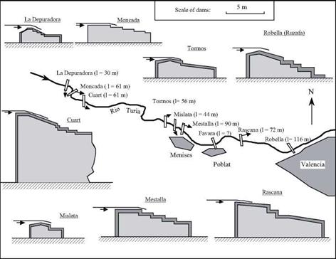
Figure 7.15 The sills of the Turia river, permitting irrigation of the huerta of Valencia from the 10th century. The sections across the structures are shown to the same scale; their lengths are indicated in parentheses. The azudes of Moncada, Mestalla, Favara, Rascana and Ruzafa are surely the oldest; the sills of Cuart and Mislata could be from after the Reconquest of the 13th century. From Fernandez Ordonez (1984).
|
sional vertical wheels) and wind-driven (such as at Malaga) – were ubiquitous in Muslim Spain. It is said that there were 5,000 mills in the region of Cordova, and 130 within the walls of Grenada alone. The mills belong to private individuals or groups of individuals, as in the Orient. It is only after the Reconquest that they become privileged feudal and ecclesiastical property, as in the Christian Occident. There was no lack of conflicts for the use of water, given the needs of the flour trade and irrigation[346].
One can find qanats on the grand plateau of Castilla, the most important being those of Madrid. From the very founding of the city by Mohamed Ist (825-886), networks of qanats are put in place to provide water for the city. They are from 7 to 10 km long, with drops of from 80 to 100 m. Indeed, it is perhaps due to the abundance and the quality of water furnished by the qanats that Madrid was chosen as capital of Spain by Philippe II, in 1561.[347] According to the geographer al-Idrissi, a large noria lifts water from the Tagus River up to the city of Toledo.
Posted by admin on 22/ 11/ 15
Arab agriculture included exotic crops such as cotton, rice, and sugar cane in addition to traditional grains and fruits. Cotton was known in Mesopotamia since the time of the Assyrians, but was essentially undeveloped. These crops require considerable water, and therefore are grown in the large irrigable zones on the shores of the Khabur, the Euphrates, and the Tigris.[325] The Muslim world uses all known existing techniques to develop irrigation. This includes derivation canals from rivers and wadis, water-lifting machines, and even drip irrigation for young plants, a technique known since the 5th century and wonderfully described in an Arab work of the 12th century.[326] The shaduf is used to lift water out of rivers and canals, but on a small scale. The bucket chain or saqqiya and the noria, are the most widely used devices. The noria sees considerable application, especially on rivers of regular flow such as the Orontes and the Khabur, and also on the middle Euphrates. We will come back to this point further on.
Qanats exist also, but it is usually impossible to tell if the origin of a particular installation is Arab, Roman, or even earlier. In Syria (where they are called foggaras), there are 45 qanats in the Palmyra region, 50 in the ghouta of Damascus, 35 between Damascus and Homs, 20 to the southeast of Homs, 50 to the east of Hama, 15 to the southwest of Aleppo, and 25 to the east of Aleppo.[327] [328] In the 12th century, Ibn Jubayr takes note of them between Homs and Damascus:
“We camped in a large village of Christians called al-Qara where no Muslim lived, and that has a caravanserai much like that of a large fortress. In the center, one can see a large basin
that is always full of water, supplied by an underground stream coming from a distant „30
source.
This axis Aleppo – Hama – Homs – Damascus, in Syria, is particularly developed and irrigated. We mentioned above the qanats, frequently encountered along this corridor, as well as the water taken from the Barada for the ghouta of Damascus (Figure 7.6).
Homs is irrigated using canals issuing from the Roman dam of Homs lake (Figure 6.33).
The steep banks of the Orontes at and around the city of Hama are irrigated thanks to large, numerous, and particularly famous norias (Figure 7.9). The oldest of these norias to which a date can be assigned (for its canal carries an inscription) was constructed in 1361 (Figure 7.7). But one cannot separate the norias from the city of Hama; in 1185, Ibn Jubayr tells us they were already there:
“On the two banks (of the Orontes), starting from the hydraulic wheels and extending regularly out, are gardens, whose tree branches hang over the water. […] On one of the banks that borders the outlying district one finds washing stations arranged like several rooms; the water, raised by a hydraulic wheel, crosses into all the hidden crannies.”[329]
 Figure 7.7 The noria al-Muhammadiya and its aqueduct at Hama, dated as 1361 from the inscription on a pillar of the aqueduct. As are the other norias of Hama, this one has been maintained and regularly renovated since its initial construction. With a diameter of 21 m, it is the largest known ancient noria (photo by the author). Figure 7.7 The noria al-Muhammadiya and its aqueduct at Hama, dated as 1361 from the inscription on a pillar of the aqueduct. As are the other norias of Hama, this one has been maintained and regularly renovated since its initial construction. With a diameter of 21 m, it is the largest known ancient noria (photo by the author).
 k»*’ k»*’
Figure 7.8 The group called the “four norias” at the entrance of the Orontes into Hama. The aqueduct of the two norias at the right has disappeared (photo by the author).
The remains of some fifteen of these norias (or the gardens that they irrigated) can be found in the archives of the 16th century of the tribunal of Hama.[330]
Qanats and norias are costly devices that provide copious quantities of water. Therefore social organization is needed to regulate their use. In the Muslim world, periodic hourly time schedules are established at a scale of about ten days. In the Syrian areas irrigated by qanats to the north of Damascus, irrigation periods are every twelve days, or rather every 24 half-days (from two hours before dawn to two hours after sunset). The unit of time is one “hour” of a hundred minutes, and through an alternating schedule a user can draw water first for a daytime period, then a nighttime period.[331] At Hama, on the other hand, weekly cycles are used to allocate water from the norias among the fields, the mosque fountains, or the public baths.
In some cases, Roman hydraulic works are brought back into service. For example, when the tenth Umeyyade caliph Hisham (724 – 743) decides to build a palace in the
|
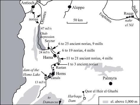
Figure 7.9 The valley of the Orontes, showing the locations of the ancient norias. The lower figure shown corresponds to the number of norias that can be reliably dated from the 16th century (from inscriptions and archive documents analyzed by Zaqzouq, 1990). The implantation of norias is particularly dense between Rastan and Sayzar, where the slope of the Orontes is a fairly regular 1.1 m/km. The indicated discharges are the mean flow of the Orontes at different points (after Delpech, girard, Robine, Roumi, 1997).
|
|
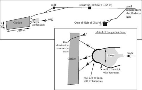
Figure 7.10 Layout of Umeyyade hydraulic installations at Qasr al-Heir al-Gharbi, and of the garden dam (after Sailby, 1990; Calvet and Geyer, 1992).
|
desert of Palmyra in 727 (at the intersection of the caravan routes, on the road between the capital Damascus and the middle Euphrates), he makes use of the ancient Roman dam of Harbaqa (Figures 6.34, 7.9).[332] This palace, known as Qasr el-Heir el-Gharbi, is supplied by an underground canal issuing from this dam that is 16.5 km long. The aqueduct supplies a reservoir that is 60 m on a side and 3.65 m deep. The aqueduct also supplies a mill, and further downstream, a nearly rectangular large cultivated area of 45 hectares, or garden. A rather strange dam (the garden dam) is built to capture water from the wadis that discharge downstream of the Harbaqa dam and to create a supplementary reservoir near the garden. Since the valley of the wadi is ill defined at this location, the ends of the dam extend in an unusual fashion along the edges of the valley (Figure 7.10).
The open canals downstream of the reservoir are earthen, but the hydraulic works and diversion gates are of stone, following the traditional practices of the region.
Mesopotamia becomes the granary of the great Arab cities. The entire irrigation system inherited from the ancient civilizations is carefully conserved, further developed, or put back into service if previously abandoned. The 35-km long grand canal called nahr Sai’d (Figure 7.11) is built on the middle Euphrates, apparently starting from the intake of the very ancient bronze-age canal Isim Yahdun Lim (Chapter 2). It brings water to the city of Rahba, founded in 820 on the riverbank by the Abbasids and subsequently relocated to the edge of the escarpment after an earthquake in 1157. This canal, along which there are several offtakes, is excavated into the plain. Therefore it cannot support gravity irrigation of large areas, as was done in the same region by the bronze-age canals.
This canal is instead used as a permanent source of water to be lifted into the gardens using saqqyas, remains of jars have been found there.[333] This practice explains why the region’s villages, all Islamic, are located directly on the canal and its offtakes. The nahr Sai’d is destined to be abandoned in the 13th or 14th century during the desertifica-
|
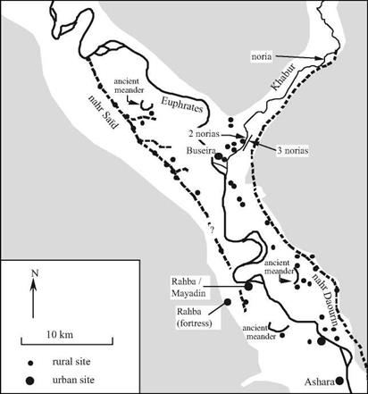
Figure 7.11 The confluence of the Khabur and the Euphrates – an area that is very developed from the 8th to the 12th centuries with the nahr Said for irrigation on the right bank and the grand navigation canal on the left bank (nahr Daourin) likely dating from the Bronze Age (Figure 2.7).
The most downstream zone (where the ancient Mari was located) is almost desert in this period. Ashara is built on the site of the ancient Terqa. After Geyer (1990), Berthier and d’Ont (1994).
|
tion of the region after the Mongol invasion (Rahba is abandoned about 1400).
The Raqqa region is further upstream on the Euphrates at the confluence of the Balih, and irrigated on the right bank from the Umeyyade period. The city of Raqqa itself, on the left bank, is an ancient Hellenistic implantation that was refounded by the Abbasid al-Mansour in 772. The caliph Haroun al-Rachid (the caliph of A Thousand and One Nights) especially develops the city during his residence there from 797 to 808. The
|
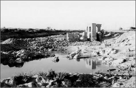
Figure 7.12 Vestiges of a noria and its mill at al-Lawriye on the lower Khabur. The photo is taken from the left bank, downstream; to the left, one can see the remains of the dam (photo by the author).
|
city benefits from an extended irrigation network whose spine is a grand canal from the Euphrates, 10 m wide and more than 16 km long, called the nahr el-Nil.[334]
Navigation on the Euphrates is important from the Umeyyade and Abassid period up until the 11th or 12th centuries.[335] Rahba (Mayadin) controls an important fluvial port. The existence of Abbassid sites all along the ancient nahr Daourin (Figure 2.12) shows that this navigation canal is to all appearances brought back into service at this period.
On the Tigris, the nahr Awan canal services the new city of Baghdad, whose population in the 13th century is nearly a million and a half inhabitants. This grand canal, parallel to the Tigris, was built by the Sassinids, then enlarged and extended to capture water from the Diyala. In the 9th century a dam is built on the Adheim (or Uzaym) river, 150 km to the north of Baghdad. This dam, 15 m high and nearly 200 m long, feeds two new irrigation canals, the nahr Batt and the nahr Rathan. Like the other dams built by
|
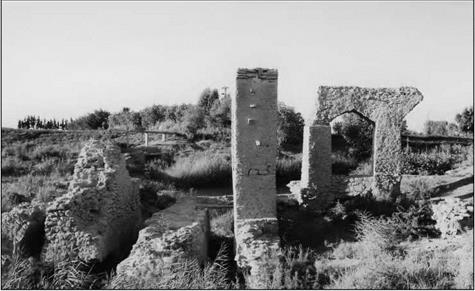
Figure 7.13 Remains of a noria at Rweshed on the Khabur, immediately upstream of its confluence with the Euphrates. This noria had three identical wheels. At the left one can see the three canals and at the right, the remains of the aqueduct (photo by the author).
|
the Arabs (those of Fars, for example), this structure is built of stones interlocked with lead seals.
During the 7th and 8th centuries the simple military camp of Basra becomes a true city with a new irrigation system fed by the Chatt al-Arab waterway, the common course of the Euphrates and the Tigris. According to al-Baladhori, a certain Hassan the Nabatian directs the drainage and irrigation works in this region. The “Hassan reservoir” at Basra is attributed to him. The first tidal mill is built at Basra in the 10th century to operate during the falling tide.[336] But despite these hydraulic works, the swamps of lower Mesopotamia cause Basra to be known for its unhealthy air and the “yellow tint of its inhabitants”, as described by Ibn Juzavy, the editor of the memoirs of Ibn Batthta.
In Arabia itself, particularly in the regions of Mecca and Medina where pilgrims congregate, numerous small dams are built on the wadis to provide water reserves through diversion of flood waters into basins and cisterns. There are some fourteen of these near Mecca and four in the region of Medina. The dams are from 2 to 11m high and 25 to 225 m long. The largest is the Qusaybah dam near Median, notable for its height of 30 m.[337] Certain dams in this region have inscriptions that would date them from the Umeyyade era. But some well-known travellers suggest otherwise. They attribute the water-resource development, needed for the caravans of pilgrims who cross the desert between the holy cities of Mesopotamia, to the queen Zubayda, cousin and wife of the caliph Haroun al-Rachid. Some descriptions of these watering places mention elaborate structures, not only the dams cited above but also the qanats when a permanent water source is found:
“Friday morning, we camped in a place called Birkat al-Marjum, where there is a basin for which they built, on the hill overlooking it, a pipeline bringing water from far away. The installation is perfect and shows how impressive human resources are and the great things that can be done with them. [….]. All of these basins, all the reservoir, wells, and rest stops between Baghdad and Mecca were developed by Zubayda, daughter of Ja’far ben Abi Ja’far al-Mansur, wife and first cousin of Harun alRashid. She devoted all of her life to this project.”[338]
The Arab cities, like the Roman cities, are major consumers of water – for baths, mosque hydrants, and caravanserais. According to Ibn Jubayr, Damascus has “nearly a hundred baths and nearly four hundred washing sites with running water everywhere” in the 12th century. Whether it be from their Roman heritage or from their Arab roots (like Rahba), these cities also have sewers.
|
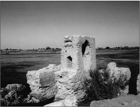
Figure 7.14 Remains of an ancient noria on the right bank of the Euphrates, downstream of the Doura Europos escarpment, about 40 km downstream of Rahba (photo by the author).
|
The Decline
Catastrophes strike the Arab Orient from the 11th century on, and especially in the 13th century. Its population declines and farmland reverts back to desert or, even worse, changes into swamps like those of the lower Mesopotamian lands. In Syria the crusades cause an exodus from rural settlement beginning in the 11th century; however this exodus is partly reversed by 12th-century agrarian reforms that encouraged a return to rural agriculture. But then the great tragedy of the Mongol invasions occurs. We have already seen how Ghengis Khan had ravaged Samarcand, Bukhara, Marw and the cities of Khorassan. And now in 1258 his grandson Hulagti razes Baghdad (later rebuilt) and irreversibly damages the Mesopotamian irrigation system. The Ottoman era begins in the 16th century; Constantinople becomes Istanbul and is endowed with new water supply systems such as the Maglova aqueduct, constructed in 1564.[339] [340]
Posted by admin on 22/ 11/ 15
All motorized equipment found in homes will generate magnetic fields when in operation. Some epidemiological studies have linked exposure to these magnetic fields with increased incidence of cancer, Alzheimer’s disease, and miscarriage. Magnetic fields from properly wired appliances drop off very quickly in an exponential relationship to your distance from them. These fields can be easily measured with a small handheld instrument called a gauss – meter, which allows the user to determine the safe distance from an appliance.
The US government has not yet set reasonable standards for safe exposure levels, nor has it taken a strong position regarding the health effects of magnetic fields. However, various government documents and public utility disclosures state that ifyou are concerned, you can practice ‘prudent avoidance” of these fields. Recommended safe exposure limits set by various experts have ranged from 0.5 milligauss to 1,000 milligauss. Hie Swedish National Energy Administration has recommended that children should not be subjected to magnetic field levels greater than 3 milligauss. The
Bau-Biologie Institute in Germany considers readings above 0.2 milligauss to be a deviation from naturally occurring conditions.
In Division 16 we include information and recommended specifications for designing and building a home in which magnetic fields transmitted by household wiring do not surpass 0.5 milligauss. You can follow the simple guidelines below to limit your exposure to magnetic fields from appliances:
• Design your home so that major appliances are located at a safe distance from sitting and sleeping areas. In doing so, remember that magnetic fields travel with ease through walls made of common building materials, and that areas located out of sight behind an appliance are also exposed. For example, placing a refrigerator back – to-back with a bed, even though separated by a wall, will continually expose a person in that bed to an elevated magnetic field.
• Duration and strength of exposure are both factors. A low-level exposure for long periods of time maybe more harmful than a brief, high-level exposure. For this reason, pay particular attention to fields that maybe generated around sleeping areas.
• We suggest that you buy and learn to use a gaussmeter. With this device, you can measure the fields emanating from appliances. For more information on choosing and operating a gaussmeter, see Division 16.
• Check your home and appliances regularly with the gaussmeter to determine whether field levels have increased. Elevated fields can sometimes indicate that an appliance has developed dangerous ground faults or is about to fail. Early detection of these fields will also decrease the risk of fire or electrocution.
Appliances and Electric Fields
Whereas magnetic fields exist only when appliances are being used, electric fields are present as long as the appliance is plugged in. Unfortunately, few appliances are manufactured in a manner that results in low electric fields. It is possible to rewire appliances so that they operate with reduced electric fields, but this requires the services of an electrician familiar with electric field shielding. Electric fields from appliances are relatively easy to control by following these suggestions:
• Keep appliances unplugged when they are not in use, especially in the bedroom. Not only will this eliminate the electric field but it will also reduce the risk of fire. Although this practice is much more common in Europe, the American Association of Home Appliances and Underwriters Laboratories has also issued a warning stating that small appliances should be unplugged as a fire prevention measure.
• Avoid using extension cords around beds or areas where your family spends a lot of time. They tend to emit high electric fields when they are plugged in.
• Use a battery-operated or wind-up clock next to the bed.
• Wire your bedroom so that the circuitry can be conveniently shut off when you go to sleep, thus eliminating the electric fields. Refer to Division 16 for details.
Posted by admin on 22/ 11/ 15
Handling drywall is a bit like waltzing: You can do it by yourself, but it’s not all that much fun.
For starters, carrying an cumbersome 70-lb. panel around a work site is a two-person job. Both of you should be on the same side of the panel, same hand supporting the bottom edge, same hand balancing the top. (Imagine ballet dancers in a line.) As you walk, lean the upper part of the panel against your shoulder.
Hanging ceilings is definitely a two-person job, especially if you’re hanging longer panels to minimize joints. Once the two (or three) of you tack up a ceiling panel, one of you can finish attaching it, while another measures or cuts the next piece.
Measuring isn’t difficult, but you need to be aware of framing quirks. For example, if the walls aren’t plumb where they meet in the corners, take at least two measurements so you’ll know what angle to cut in the end of the panel you’re installing. If the two readings vary only slightly—say, !4 in.—there’s no need to trim the end of the panel because taping and filling the joint will take care of the gap. But if readings vary more than % in., trim the panel end at an angle, so there’s no gap where it abuts the out-of-plumb wall.
Second, if you’re running panels perpendicular to the framing, butt ends must meet over joist or stud centers. If framing members aren’t evenly spaced, you may occasionally need to trim a butt end to make it coincide with a joist center.
Last, and most important, cut panels about / in. short so you never need to force a panel into place. Forcing will crush an end that you’ll need to repair later. If it’s a ceiling panel, the gap will eventually be covered by wall panels fitted snugly against it.
Once you’ve cut a panel, snap parallel chalklines across its face, indicating stud or joist centers behind the drywall once it’s in place. Guided by these lines, your screws or nails will always bed into framing.
Cutting drywall is literally a snap if the blades in your utility knife are sharp. Run the blade along a drywall T-square or a framing square, if that’s all you have. In one pass, score the paper covering. Then grasp the smaller section and snap it sharply away from the cut, breaking the gypsum core along the scored line. Then cut through the paper on the backside, and set aside the waste section.
Cutting is usually easiest if you lean the panel against a wall so you don’t need to bend over. But if you’ve already stacked panels on the floor, you
Posted by admin on 22/ 11/ 15
The time dimension appears in the form of a first order time derivative in the constitutive mechanical model (Eqs. 11.3, 11.4) and in the diffusion problems though the storage term (Eq. 11.6). We will here discuss the time integration procedure and the accuracy and stability problems that are involved.
11.2.6.1 Time Integration – Diffusion Problems
The period to be considered is divided into time steps. Linear development of the basic variable with respect to the time is generally considered within a time step:
t — tA tB — t
p = – PB + – B PA (11.26)
tB — tA tB — tA
where the subscripts A, B denote, respectively, the beginning and the end of a time step. Then the pressure rate is:
dp _ Pb – Pa _ A p dt tB — tA At
This time discretisation is equivalent to a finite difference scheme. It allows the evaluation of any variable at any time within a time step.
The balance equation should ideally be satisfied at any time during any time step. Of course this is not possible for a discretised problem. Only a mean assessment of the balance equation can be obtained. Weighted residual formulations have been proposed in a similar way as for finite elements (Zienkiewicz et al., 1988). However, the implementation complexity is too high with respect to the accuracy. Then the easiest solution is to assess only the balance equation at a given time, denoted tT, inside the time step tA to tB, such that a time variable, т, is defined:
tT tA
T =
tB — tA
All variables have then to be evaluated at the reference time, tT. Different classical schemes have been discussed for some decades:
• Fully explicit scheme – t = 0: all variables and the balance are expressed at the time step beginning, where everything is known (from the solution of the preceding time step). The solution is, therefore, very easily obtained.
• Crank-Nicholson scheme or mid-point scheme – t = 1/2
• Galerkin’s scheme – t = 2/3
• Fully implicit scheme – t = 1
The last three schemes are functions of the pore pressure/temperature/concentration at the end of the time step, and may need to be solved iteratively if non-linear problems are considered.
For some problems, phase changes, or similar large variations of properties, may occur abruptly. For example, icing or vaporising of water is associated with latent heat consumption and abrupt change of specific heat and thermal conductivity. Such rapid change is not easy to model. The change in specific heat may be smoothed using an enthalpy formulation, because enthalpy, H, is an integral of the specific heat, c. Then the finite difference of the enthalpy evaluated over the whole time step gives a mean value, c, and so allows an accurate balance equation:
|
= cdT
|
(11.29)
|
|
T
|
|
Hb – Ha
|
(11.30)
|
|
tB — tA
|
Posted by admin on 22/ 11/ 15
Start by consulting local building codes. They’ll specify the type, thickness, and number of drywall layers you must install throughout the house.
It’s possible to estimate drywall materials from a set of blueprints, but even the pros prefer to walk the job, measuring walls and ceilings and noting where using longer panels will minimize joints. That way, you get exactly the panel lengths you need.
As you walk through the rooms, record your findings on J4-in. graph paper. Use one sheet of paper per room, letting each square equal 1 ft. Then, when your materials arrive, you’ll know which room gets what.
1. Start by measuring the width and length of each room. In general, think in 2-ft. increments. That is, if a wall is 10 ft. 6 in. long, plan to buy 12-ft. panels and run them horizontally in order to get the fewest joints. If studs aren’t spaced a standard 16 in. on center, note that on your graph paper. (If you’re not sure of stud and joist spacing, use a stud finder.) Calculate the number of panels of each dimension you’ll need for each room.
2. Note door and window locations and dimensions, but don’t deduct their square footage from the room total. Portions of panels cut out for windows and doors will yield a high percentage of nonfactory edges and butt joints, so it’s
I Estimating Drywall Needs
easiest to discard such scrap or piece it together in out-of-way places, such as closets.
3. Note the ceiling height. If the ceiling is 8 ft., two standard 4-ft. by 8-ft. wall panels run horizontally will reach it; if they’re 9 ft. high, use two horizontal 54-in.-wide panels. If ceilings are higher than 9 ft., you may want to rent scaffolding and a drywall lift.
4. Note the direction and spacing of ceiling joists. Panels run perpendicular to ceiling joists (or rafters, if a cathedral ceiling) are less likely to sag.
5. Special rooms. Install WR (water-resistant) drywall in laundry rooms, behind kitchen sinks, and in bathrooms other than in tub/shower areas. Cover tub/shower areas with cementitious board if they’ll be tiled. Install 58-in. type-X dry – wall on shared walls between the garage and living space. If existing plaster is in bad shape and you don’t want to tear it out, cover it with /4-in. or 58-in. drywall.
6. Special features include arches, curved stairwells, barrel ceilings, odd nooks, built-in bookcases or cabinets, and the like. For curves, you need flexible /4-in. drywall. Expect a lot of waste around complex areas, such as stairways.
Calculating DrywaU Square Footage
|
Chapter 4). Green or wet lumber will shrink as it dries, causing cracks and nail pops in a new drywall job, so don’t use it.
|
PANEL LENGTH (ft.)
|
SQUARE FEET PER PANEL*
|
|
NUMBER OF PANELS
|
TOTAL
SQUARE FEET
|
► Sight along studs and ceiling joists to see if they are aligned in a flat plane. To be more precise, stretch a taut string or hold a straightedge across the framing members. Running
|
|
8
|
32
|
X
|
40
|
= 1,280
|
|
9
|
36
|
X
|
35
|
= 1,260
|
drywall panels perpendicular to framing will
|
|
10
|
40
|
X
|
30
|
= 1,200
|
help conceal minor misalignments, as will textured finish surfaces. But it’s better to
|
|
12
|
48
|
X
|
25
|
= 1,200
|
adjust misaligned framing, especially if the
|
|
14
|
56
|
X
|
20
|
= 1,120
|
drywall surface will be brightly lit or otherwise prominent. If a stud is misaligned more than
|
|
16
|
64
|
X
|
20
|
= 1280
|
/4 in., your options include hammering it into line, power-planing it down, and shimming
|
|
Total
|
|
|
|
7,340
|
up low spots, as described in Chapter 8
|
► Use a framing square to determine if * Calculations assume that all panels are 4 ft. wide. corners are square, and make sure there’s
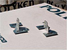
blocking in the corners, so you’ll have something to attach the panel edges to. Or you can use drywall clips to "float" the corners.
|
► Install steel nail guards to protect plumbing pipes and electrical cables within U4 in. of joist or stud edges. Few things are as frustrating as discovering a leak or an electrical short after the drywall is up. Then make a final check of the electrical outlet boxes. They should be securely attached to the framing with their edges flush with the drywall face (see Chapter 11).
► If appropriate to your climate, plastic vapor barriers or insulation should be in place now, as described in Chapter 14. If you’re drywalling over rigid foam insulation—say, on a cathedral ceiling—first affix 1X2 furring strips so you’ll have something to screw to.
Do not attach drywall directly to the foam because the insulation expands, contracts, and compresses.
9. Finally, make a master list of all the dry – wall you need for the complete renovation.
GETTING READY TO HANG DRYWALL
Here’s a final checklist before installing drywall:
► The building should be dry and relatively warm (between 60°F and 70°F). Keep temperatures constant. If a room becomes too hot (80°F or above), joint compounds may dry too quickly and crack. If the heating system is inoperable, rent a portable heater. Ventilation is also important for drying: Drying-type joint compounds evaporate a lot of water.
►    Framing lumber must be dry: 15 percent to 19 percent moisture content is optimal (see Framing lumber must be dry: 15 percent to 19 percent moisture content is optimal (see
| |



 Metric sizes are common in many places of the world. Plumbers in the United States still work primarily with customary measurements in terms of inches. However, you may find times when metric equivalents are useful. For this reason, I’m providing Figure 11.2
 Figure 7.7 The noria al-Muhammadiya and its aqueduct at Hama, dated as 1361 from the inscription on a pillar of the aqueduct. As are the other norias of Hama, this one has been maintained and regularly renovated since its initial construction. With a diameter of 21 m, it is the largest known ancient noria (photo by the author).


 Framing lumber must be dry: 15 percent to 19 percent moisture content is optimal (see