SMALL REPAIRS

Small cracks or holes in plaster can be filled with patching plaster or a setting-type joint compound such as Durabond 90, which sets in 90 minutes. Because joint compound is softer, sands easily, and sets slower than patching plaster, it’s easier to work with. Setting-type joint compounds (also known as hot mud) are also better for patching than drying-type joint compounds, which just aren’t as strong. Note: To ensure a good bond, strip paint from the surfaces you’re patching and sand the adjacent areas lightly before applying compound.

Small cracks in plaster are repaired by stripping surface paint, cleaning loose plaster, and under­cutting the cracks slightly with a knife or a small, sharp-pointed lever-type can opener (also called a "church key”) Undercutting allows the patching material to harden and form a key that won’t fall out. Before patching, wet the exposed plaster well and brush on a PVA (polyvinyl acetate) bon­der such as Plasterweld® or Elmer’s White Glue® to bond the patch to the old plaster.

Over the crack, stretch a length of self-adhering fiberglass mesh. Then use a taping knife to spread the patching material into the crack. Leave the first coat of joint compound a little rough so the second adheres better. After lightly sanding the
first coat, apply the second, feathering it out to blend-in the patch’s edges.

When the patch dries, sand it lightly with fine, 220-grit sandpaper, wipe it clean, allow it to dry thoroughly, and prime the patch with an oil – based primer.

Large cracks often accompany sections of bowed or sagging plaster, which have pulled free from the lath behind. If the plaster is sound— not crumbling—you can reattach it to the lath using type-W drywall screws and plaster washers, which fit under the heads of the screws. A screw gun is good for this operation.

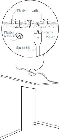
However, before you attach the screws, mark their locations on the plaster, and use a spade bit to countersink a hole ‘/ in. deep for each washer.

Sunk below the surface of the plaster, the screw heads and washers will be easy to cover with patching compound.

Place screws and washers every 8 in. to ‘0 in. on both sides of the crack and anywhere else the plaster seems springy and disconnected from the lath. Once you’ve stabilized the crack in this man­ner, scrape, tape, and fill it, as described earlier.

Small holes the size of a removed electrical out­let are easy to fill if the lath is still in place. Remove any loose plaster, brush out the debris, wet the lath and the surrounding plaster well, brush on a PVA bonder, and trowel in patching material. Leave the first coat a little rough, let it dry well, and apply bonder again before trowel­ing in a second, smooth coat.

Patching I Cracked Plaster

image770

Cracked plaster often means that it has pulled free from its lath. Use screws and plaster washers to reattach it, countersinking them so they’ll be easier to patch.

Patching Holes I in Plaster

image771

image772

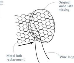
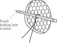
If plaster lath has been cut out, replace it before patching the hole. Insert and secure a small section of wire lath with a wire looped around a pencil, as shown. Twirl the pencil to draw the wire lath tight to the back of the plaster, then fill the hole with two coats of patching plaster. Unwind the wire and snip it when the first coat is hard.

If the hole has no lath behind it, you’ll need to add some. Scrape the loose plaster from the edge of the hole. As shown in "Patching Holes in Plaster,” on p. 373, cut a piece of metal lath larger than the hole and loop a short piece of wire through the middle of the lath. Then, holding the ends of the wire, slide the lath into the hole. To pull the lath tight against the back of the hole, insert a pencil into the front of the loop and turn the pencil like an airplane propeller until the wire is taut. The pencil spanning the hole holds the lath in place.

After wetting the lath and surrounding plaster, spread a rough coat of compound into the hole. When the coat has set, unwind the wire, remove the pencil, and push the wire into the wall cavity. The hardened plaster will hold the metal lath in place. Trowel on the finish coat.

Large holes with lath intact should be partially patched with a piece of drywall slightly smaller than the hole. Because a hole with square corners is easier to patch than an irregular one, square up the edges of plaster, using a chisel or a Dremel tool with an abrasive wheel. (Wear goggles.) Be careful not to cut through the lath. Use type-W drywall screws to attach the drywall to the lath behind, stretch self-adhering fiberglass mesh tape around the perimeter of the patch, and apply joint compound or patching plaster as described earlier. For best results, the drywall should be slightly thinner than the existing plaster, so you have some room to build up and feather out the patch.

As an alternative, pegboard is a dandy sub­strate for such patches because you can cut it easily with a jigsaw to fit irregular holes. Hold a sheet of!4-in. pegboard over the plaster, eyeball and trace the shape of the patch through the holes in the pegboard, and screw the pegboard to the lath—textured side out. The patching plaster will ooze through the holes in the pegboard and harden in the same manner that plaster keys into the spaces between lath strips.

Texturing Drywall and Plaster

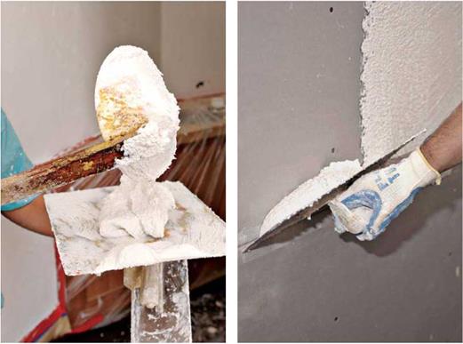
Joint compound is a marvelous medium for texturing a drywall patch or matching the texture of existing plaster. All that’s needed is a little ingenuity.

► For a stippled plaster look, place joint compound in a paint tray, thin it with water till it is the consistency of thick whipping cream, and roll it onto the wall or ceiling using a stippled roller. Don’t over-roll the compound, or you’ll flatten the stipples.

► Create an irregular "splatter" texture by thinning the compound to a heavy-cream consistency, sucking it into a turkey baster and squirting it onto the wall.

► For an open-pore, orange-peel look, use a stiff-bristle brush or whisk broom to jab compound that is just starting to dry. Jab lightly and keep the bristles clean.

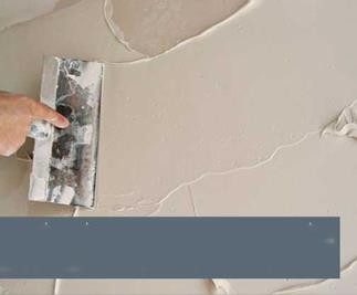
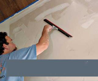
► To achieve the flat but hand-tooled look of real plaster, apply the compound in short, intersecting arcs. Then knock down the high spots with a rubber-edged Magic Trowel®, as shown.

► If you’re trying to duplicate a slightly grainy but highly finished plaster surface, trowel on the topping coat as smoothly as possible and allow it to dry. Then mist the surface slightly and rub it gently with a rubber-edged grout float.

Подпись: Before the compound starts to set, use a rubber-faced Magic Trowel to knock down high spots and partially smooth out the knife marks. The trowel should glide. Unload excess compound into your mud tray after each pass, and sponge the rubber edge clean every four or five passes.

You can achieve the irregular, hand-tooled look of plaster by covering drywall with joint compound applied in tight, intersecting arcs. Because of its crack-resistance, use 90-minute or 120-minutes setting-type compound. It’s okay if the drywall isn’t completely covered.

I

PLASTERING

image766

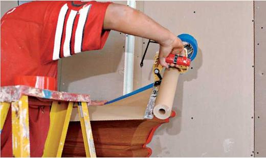
1. If casing, baseboards, or floors are already installed, cover them with paper and tape to protect them from plaster splatters.

image767 image768

Подпись:

2. Mix the plaster to the consistency of soft – serve ice cream before ladling it onto a mason’s hawk. For skim-coat plaster, follow the manufacturer’s mixing instructions, which typically recommend adding 12 qt. to 15 qt. of water for each 50-lb. bag of plaster.

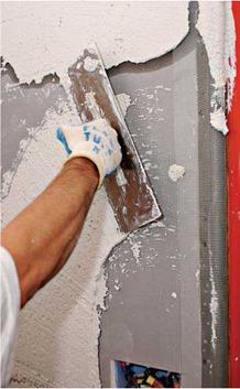
3. To prevent cracking, cover blueboard seams with self-adhering mesh tape. Load your trowel from the hawk and…

Подпись: Repair or Replace Plaster? To decide if plaster should be repaired or replaced, first assess how well it is attached to the lath. To do this, near stains, cracks, holes, or sagging sections, press the plaster with your hand. If the plaster is springy, it has probably separated from its lath and must be reattached before you try to repair it. ► If the plaster has a few surface cracks and isolated holes but is stable, it can be repaired. ► If there's widespread discoloration and there are cracks wider than 4, in., but the plaster's basically stable, cover it with ‘/,-in. or 3/s-in. drywall or replace it. ► If you see water stains, crumbling plaster, and widespread cracking or sagging surfaces, remove the plaster and replace it with drywall. If there are water stains, of course, eliminate their source before doing any other work. Widespread sagging suggests that lath has pulled away from framing. Although lath can be reattached, concomitant plaster damage will usually be so extensive that you're better off tearing out the plaster.

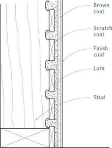
the gaps in the lath and becomes a mechanical key when it hardens.

3. Trowel on, then roughen the brown coat after it has set slightly.

4. Trowel on a finish, or white coat, which becomes the final, smooth surface.

In the old days, plasterers often mixed animal hair into scratch and brown coats to help them adhere. Thus old plaster that’s being demolished is nasty stuff to breathe. The finish coat was usu­ally a mixture of gauging plaster and lime, for uniformity. Scratch coats and brown coats were left rough and were often scratched with a plas­terer’s comb before they set completely, so the next coat would have grooves to adhere to. Finish coats were quite thin (Иб in.) and very hard.

Lath can be a clue to a house’s age. The earli­est wood lath was split from a single board so that, when the board was pulled apart (side to side), it expanded like an accordion. Although metal lath was available by the late 1800s (it was patented in England a century earlier), split wood lath persisted because it could be fashioned on-site with little more than a hatchet. By 1900, however, most plasterers had switched from lime plaster to gypsum plaster, which dried much more quickly. And about the same time, plasterers began using small paper-coated panels of gypsum instead of wood or metal lath. Called gypsum lath or rock lath, the panels were so easy to install that they dominated the market by the 1930s. But time and techniques march on. As mentioned earlier, after World War II, drywall all but replaced plaster as a residential surface.

I Keying Plaster to Wood

image769

This plaster cross section shows how the scratch coat of plaster oozes through the lath and hardens to form keys, the mechanical connection of plaster to wood.

Physical Aspects: Various Terms of Coupling

A large number of different phenomena may be coupled. It is impossible to discuss here all potential terms of coupling, and we will restrict ourselves to some basic cases often implied in environmental geomaterial mechanics. In the following para­graphs, some fundamental aspects of potential coupling are briefly described.

11.3.2.1 Hydro-Mechanical Coupling

In the case of hydro-mechanical coupling, the number of d. o.f. per node will be 3 (2 displacements +1 pore pressure) for 2D analysis and 4 (3 displacements +1 pore pressure) for 3D analysis.

Coupling mechanical deformation of soils or rock mass and water flow in pores is a frequent problem in geomechanics. The first coupling terms are related to the influence of pore pressure on mechanical equilibrium through Terzaghi’s postulate (or through any other effective stress concept or net stress use, cf. Eq. 9.20):

a = a’ + uI

with the effective stress tensor a’ related to the strain rate tensor thanks to the con­stitutive Eq. 11.3, and the identity tensor I.

The second type of coupling concerns the influence of the solid mechanics be­haviour on the flow process, which comes first through the storage term. Storage of water in saturated media is mainly due to pores strains, i. e. to volumetric changes in the soil/rock matrix:

Another effect, which may be considered, is the permeability change related to the pore volume change, which may, for example, be modelled by the Kozeny – Carman law as a function of the porosity K = K (n).

Biot proposed an alternative formulation for rocks where contacts between grains are much more important than in soils. Following Biot, the coupling between flow and solid mechanics are much more important (Detournay & Cheng, 1991; Thimus etal., 1998).

The time dimension may cause some problems. First, an implicit scheme is used for the solid mechanics equilibrium and various solutions are possible for the pore pressure diffusion process. Consistency would imply use of fully explicit schemes for the two problems. Moreover, it has been shown that time oscillations of the pore pressure may occur for other time schemes. Associated to Terzaghi’s postulate, oscillations could appear also on the stress tensor, which can degrade the numerical convergence rate for elasto-plastic constitutive laws.

When using isoparametric finite elements, the shape functions for geometry and for pore pressure are identical. Let us consider, for example, a second or­der finite element. As the displacement field is of second order, the strain rate field is linear. For an elastic material, the effective stress tensor rate is then also linear. However, the pore pressure field is quadratic. Then Terzaghi’s postulate mixes the linear and quadratic fields, which is not very consistent. Some authors have then proposed to mix in one element quadratic shape functions for the ge­ometry and linear shape functions for pore pressure. But then problems arrive with the choice of spatial integration points (e. g. should there be 1 or 4 Gauss points?).

Numerical locking problems may also appear for isoparametric finite elements when the two phase material (water plus soil) is quite incompressible, i. e. for very short time steps with respect to the fluid diffusion time scale. Specific elements have to be developed for such problems.

Pedestrian Conflict Area Classifications

The above classifications appropriately describe general conditions of vehicular traffic conflict in urban areas. A second type of conflict is vehicle/pedestrian interaction. The magnitude is mostly determined by the land use of the abutting properties. Three clas­sifications of pedestrian night activity levels and types of land use with which they are typically associated are used in the lighting criteria tables:

High. Areas with significant numbers of pedestrians expected to be on the side­walks or crossing the streets during darkness. Examples are downtown retail areas and areas near theaters, concert halls, stadiums, and transit terminals.

Medium. Areas where lesser numbers of pedestrians utilize the streets at night. Typical are downtown office areas; blocks with libraries, apartments, and neigh­borhood shopping; industrial areas; older city areas; and streets with transit lines.

Low. Areas with low volumes of night pedestrian usage. These can occur in any of the cited roadway classifications but may be typified by suburban single-family streets, very-low-density residential developments, and rural or semirural areas.

The choice of appropriate lighting levels is an engineering decision. If needed, 1-h pedestrian counts can be taken during the first hour of darkness. The volume of pedes­trians that warrants increased lighting levels is not fixed but is a local option. However, the following volumes might be considered as a guide:

Low 10 or fewer

Medium 11 to 100

High Over 100

These volumes represent the total number of pedestrians walking on both sides of the street plus those crossing the street at nonintersection locations in a typical block. The lighting levels at intersections are already considered by the increased illumination for the points of conflict.

Coupling Various Problems

11.3.1 Finite Element Modelling: Monolithical Approach

Modelling the coupling between different phenomena should imply the need to model each of them and, simultaneously, all the interactions between them. A first approach consists in developing new finite element and constitutive laws especially dedicated to the physical coupled problem to be modelled. This approach allows taking accurately all the coupling terms into account. However there are some draw­backs that will be discussed in Section 11.3.4. Constitutive equations for coupled phenomena will be discussed in the following sections.

The number of basic unknowns and, consequently, the number of degrees of freedom – d. o.f. – per node are increased. This has a direct effect on the computer time used for solving the equation system (up to the third power of the total d. o.f. number). Coupled problems are highly time consuming.

Isoparametric finite elements will often be considered. However, some specific difficulties may be encountered for specific problems. Nodal forces or fluxes are computed in the same way as for decoupled problems. However, the stiffness matrix evaluation is much more complex, as interactions between the different phenomena are to be taken into account. Remember that the stiffness or iteration matrix, Eq. 11.25, is the derivative of internal nodal forces/fluxes with respect to the nodal unknowns (displacements/pressures/etc…). The complexity is illustrated by the following scheme of the stiffness matrix, restricted to the coupling between two problems.

The part of the stiffness matrix in cells 1-1 and 2-2 are similar, or simpler, than the ones involved in uncoupled problems. The two other cells, 1-2 and 2-1, are new and may be of a greater complexity. Remember also that the derivative considers internal nodal forces/fluxes as obtained numerically, i. e. taking into account all numerical integration/derivation procedures. On the other hand, the large difference of orders of magnitude between different terms may cause troubles in solving the problem and so needs to be checked.

Numerical convergence of the Newton-Raphson process has to be evaluated care­fully. It is generally based on some norms of the out-of-balance forces/fluxes. How­ever, coupling often implies the mixing of different kinds of d. o.f., which may not be compared without precaution. Convergence has to be obtained for each basic problem modelled, not only for one, which would then predominate in the computed indicator.

FACILITY AND AREA CLASSIFICATIONS

The following descriptions of facility types and area classifications are used to describe the warranting conditions and design needs of roadway lighting.

7.15.1 Roadway, Pedestrian Walkway, and Bikeway Classifications [3, 6]

• Freeway. A divided major roadway with full control of access (no crossings at grade). This definition applies to toll as well as nontoll roads.

• Freeway A: Roadways with greater visual complexity and high traffic volumes. Usually this type of freeway will be found in major metropolitan areas in or near the central core and will operate through some of the early evening hours of darkness at or near design capacity.

• Freeway B: All other divided roadways with full control of access.

• Expressway. A divided major arterial highway for through traffic with full or par­tial control of access and generally with interchanges at major crossroads. Parkways are expressways for noncommercial traffic within parks and parklike areas.

• Major. That part of the roadway system that serves as the principal network for through-traffic flow. These routes connect areas of principal traffic generation and important rural roadways leaving the city. These routes are often referred to as arte- rials, throughfares, or preferentials and are sometimes subdivided into primary and secondary, but these distinctions do not affect the roadway lighting.

• Collector. Roadways serving traffic between major and local streets. These are streets used mainly for traffic movements within residential, commercial, and industrial areas. They do not handle long through trips. Collector streets may be used for truck or bus movements and give direct service to abutting properties.

• Local. Roadways used primarily for direct access to residential, commercial, industrial, or other abutting property. They do not include roadways carrying through traffic. Long local roadways will generally be divided into short sections by collector roadway systems.

• Roundabout. A circular intersection with yield control of all entering traffic, chan­nelized approaches, counterclockwise circulation, and appropriate geometric curvature to ensure that travel speeds on the circulatory roadway are typically less than 30 mi/h (50 km/h) [20].

• Alleys. A narrow public way within a block, generally used for vehicular access to the rear of abutting properties.

• Sidewalks. Paved or otherwise improved areas for pedestrian use, located within public street rights-of-way that also contain roadways for vehicular traffic.

• Pedestrian ways. Public sidewalks for pedestrian traffic generally not within rights-of-way for vehicular traffic roadways. Included are skywalks (pedestrian overpasses), subwalks (pedestrian tunnels), walkways giving access to park or block interiors, and crossings near centers of long blocks.

• Bicycle lanes. Any facility that explicitly provides for bicycle travel.

Advection Diffusion Processes

Let us first consider a purely advective process. In this case, the transport is gov­erned by the advection Eq. 11.11 and by the balance Eq. 11.6. Associating these two equations, one obtains:

(VTC). ffluld + C = 0 (11.45)

diff v ‘

which is a hyperbolic differential equation. It cannot be solved by the finite element or finite difference problem, but by characteristic methods. The idea is to follow the movement of a pollutant particle by simply integrating step by step the fluid velocity field. This integration has to be accurate enough, as errors are cumulated from one step to the next.

On the other hand, if advection is very small compared to diffusion, then the finite element and finite difference methods are really efficient.

For most practical cases, an intermediate situation holds. It can be checked by Peclet’s number, Eq. 11.13, which is high for mainly advective processes and low for mainly diffusive ones. As diffusion has to be taken into account, the numeri­cal solution must be based on the finite element method (the finite difference one may also be used but will not be discussed here). However, numerical experiments show that the classical Galerkin’s formulation gives very poor results with high spatial oscillations and artificial dispersion. Thus, new solutions have been proposed (Zienkiewicz & Taylor, 1989, Charlier & Radu, 2001). A first solution is based on the use in the weighted residual method of a weighting function that differs from the shape one by an upwind term, i. e. a term depending in amplitude and direction on the fluid velocity field. The main advantage of this method is the maintenance of the finite element code formalism. However, it is never possible to obtain a highly accurate procedure. Numerical dispersion will always occur.

Other solutions are based on the association of the characteristic method for the advection part of the process and of the finite element method for the diffusive part (Li et al., 1997). The characteristic method may be embedded in the finite element code, which has a strong influence on the finite element code structure. It is also possible to manage the two methods in separated codes, as in a staggered procedure (cf. Section 11.3.4).

Windmills

The origin of the windmill is controversial. In a manuscript on Pneumatics, Heron of Alexandria includes the description of a wheel driven by the wind and driving the pis­ton of an organ. But the authenticity of this passage has not been resolved – it could have been added during the Islamic period. In any case, even if this passage is authentic, the link between this invention and the appearance of the true windmill in central Asia seems to be very weak.

The backdrop of Heron’s apparent reference to a windmill is the ubiquitous presence of water mills on all of the rivers. On the Tigris at Baghdad, on the Seguro at Murcia, on the Ebre at Saragossa, there are even boat-mounted water mills. Mills are the indis­pensable tools of an agricultural economy. But on the Persian plateau there are few, if any, watercourses. This undoubtedly led to the invention of the windmill at an indeter­minate date but perhaps prior to the Arab conquest. In about 660 a Persian had affirmed to the caliph Omar that a windmill could be built. The windmills of Seistan (to the east of Khorassan) were known to Arab geographers from the 9th century on, in particular to the Banu Musa brothers.[363] These mills turn on a vertical axis; their vanes are inside a chamber at the top of a sort of tower, open to the four cardinal directions with shutters that one can close depending on the direction or the force of the wind. The rotation of the axle directly turns a millwheel that is in the chamber just below. These mills are described somewhat later by Chinese authors who give a precise account of them:

“In the western countries called Herat and Samarcand, there are many windmills. Brick walls are built to form a sort of house having openings at its summit, facing the four directions, out­side of which screens can be placed to direct the wind. In the chamber below is placed a wood­en axle, with sails (literally planks to ride the wind) fixed to it. Whatever the direction of the wind, the axle always turns, and the stronger the wind, the more work can be accom­plished.”[364]

TAPING AND FINISHING

To finish drywall, seal the panel joints with tape or cornerbead, then cover them with joint com­pound. Typically, three coats of compound are applied in successively wider coats and sanded after each application. The first coat, usually a high-strength taping compound, embeds the tape. The second coat should be a thin layer of topping compound or all-purpose compound that you feather out to hide the joints. With the third coat, you feather out the compound farther, creating a smooth, finished surface. (See "Joint Compounds,” on p. 358, for more about these materials.)

First coat. Fill nail holes or screw dimples in an X pattern: One diagonal knife stroke applies the compound, and the other stroke removes the excess.

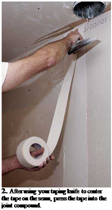
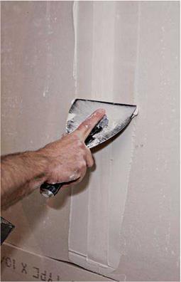
If you use paper tape on the joints, apply a swath of taping compound about 4 in. wide down the center of the joint. Press the tape into the 1. Before applying paper tape, cover the seam

center of the joint with a 6-in. taping knife. Then with an generous bed of joint compound apply compound over the tape, bearing down so you remove the excess.

If you use self-sticking mesh tape, stick it directly over the joint and apply the bedding compound over it. In other words, don’t apply a bed of compound first. Mesh tape must be bedded in setting-type compound, as explained earlier in this chapter.

AN ORDERLY

All that raw drywall can seem a bit overwhelm­ing, so here’s a taping and mudding sequence that starts easy, so you can become comfortable with the tools and materials:

► Screw and nail holes

► Bevel-edge joints (the long edges of panels)

► Butt-edge joints

► Outside corners

► Inside corners.

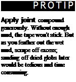
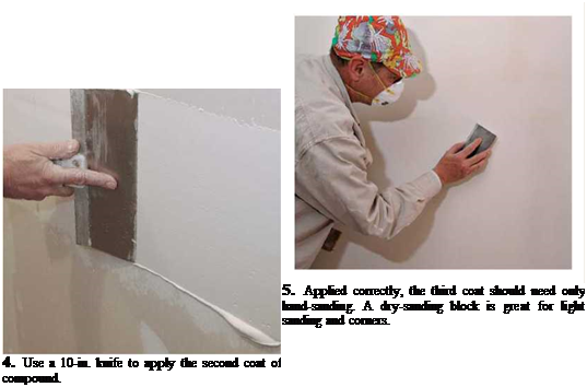
Подпись: 2. After using your taping knife to center the tape on the seam, press the tape into the joint compound. Подпись: JRLY Finish M *>лл**» ч АІІЛШІІІЧЛІ m Подпись: 3. After applying a layer of compound over the tape, remove the excess. If the tape moves, you're pressing too hard or your taping knife needs to be cleaned. (Steps continue on next page.)Подпись: PROTIP Apply joint compound generously. Without enough mud, the tape won't stick. But as you feather out the wet mud, scrape off excess; sanding off dried globs later would be tedious and time consuming. 1111 image758Have a pail of clean water and a sponge handy so you can rinse your taping knives periodically. They glide better if they’re clean. Keep the job site clean, too: If you drop a glob of compound on the floor, scrape it up and discard it so you don’t track it around the house.
TAPING AND FINISHING

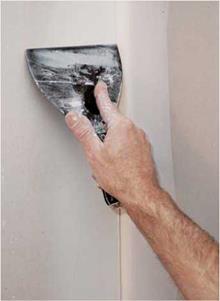
Подпись: Allow the first coat to dry thoroughly before sanding it. This will take about a day, if the room temperature is 65°F to 70°F and there's adequate ventilation. Sand lightly with 120-grit to 150-grit sandpaper. Because there are two more coats to come, this taping coat can be left a little rough. Second coat. The second coat is also called the filler coat, and with this one you'll apply the most compound. At this stage, many professionals use Подпись: The Art of Inside CornersПодпись: Use paper tape for inside corners. After applying a bed of compound to both surfaces, crease the tape, and place it in the corner. Then use a double-edged corner knife to press the tape into the compound before spreading a second layer of compound over the tape. Some pros snort at corner knives, preferring to use a flat 6-in. taping knife to press tape into compound, one edge at a time. When feathering- out joint compound, pros allow the compound to dry on one side of the corner before working on the adja-cent surface. In other words, "Never run wet mud into wet mud." image761a 10-in.-wide taping joint knife and feather out the seams roughly 8 in. to 10 in. wide. After applying the compound, smooth it out with an even wider blade—say, a 14-in. trowel.

As you’ll learn when working with joint com­pound, the lower the angle of the blade and the less pressure, the easier it is to smooth and feather (spread out) the mud. The greater the angle and pressure, the more compound you’ll remove.

This is easier to do than explain. Because butt – end joints are not beveled, they’ll mound slightly at the center of the seam. That’s okay. Use a 10-in. taping knife to build up the compound on both sides of the joint, feather out the edges, and then smooth the center. Consequently, butt-end joints may need to be wider than bevel-edge joints.

You may often need to feather butt-end joints 16 in. to 20 in. wide.

When this second coat is dry, sand with 150-grit to 220-grit paper. A pole sander will extend your reach and enable you to sand longer without tiring, but don’t sand too aggressively or you’ll abrade the paper face or expose the tape. Easy does it.

Third coat. The third coat is the last chance to feather out the edges, so use a premixed, all­purpose, drying-type compound, which is easy to thin out and sand because it has a fine consistency and dries quickly. Although premixed compound will be the right consistency, it’s okay to add a little water to thin it even more.

Because the third coat is only slightly wider (2 in.) than the second coat, you’ll be applying a relatively small amount of compound. Use a 12-in. trowel, with a light touch. Some pros thin this coat enough to apply it with a roller, and then smooth it with a trowel, so there are no trowel marks when they’re done.

image762"Подпись: MOPПодпись: TAPING TOOLSПодпись: hanicalimage763

Hand-sand the final coat, using fine, 220-grit sandpaper or a very fine sanding block. Shining a strong light on surfaces will highlight the imper­fections you need to sand.

Wrap up. If you intend to texture the surfaces, the third coat doesn’t need to be mirror smooth. Even so, don’t scrimp on the second coat, or else the joints may be visible through the texture

To give yourself the greatest number of deco­rating options in the future, paint the finished drywall surface with a coat of flat, oil-based primer. It will seal the paper face of the drywall and provide an excellent base for any kind of paint or wall covering.

DRYWALL REPAIRS

To keep solutions concise, let’s divide drywall repairs into four groups: nail pops and surface blemishes; fist-size holes through the drywall; larger holes; and discolored, crumbling, or moldy drywall. Any repair patches should be the same thickness as the damaged drywall.

Popped nails and screws are generally a quick fix: Drive another nail or screw 1 h in. away from the popped one to secure the drywall. If it’s a popped screw, remove it and fill the hole. Cover both the old hole and the new screw with at least two coats of joint compound. If it’s a popped nail, don’t try to remove it; drive it slightly deeper to dimple the drywall.

When a piece of drywall tape lifts, pull gently until you reach a section that’s still well stuck. Use a utility knife to cut free the loose tape, cover the exposed seams with self-sticking mesh tape, and apply two or three coats of compound—sanding lightly after each. Drywall repair kits with precut patches are available at most home centers.

To repair drywall cracks, cut back the edges of the crack slightly to remove crumbly gypsum and provide a good depression for a new filling of joint compound. Any time the paper face of dry – wall is damaged, cover the damaged area with self-adhering fiberglass mesh tape. Then apply three coats of joint compound. Because the repair area is small, it doesn’t matter what type of compound you use, though setting-type com­pounds are preferred.

Small holes in drywall are often caused by doorknobs, furniture, or removed electrical out­let boxes. Clean up the edge of the hole so the surface is flat. Then cover the hole with self­adhering fiberglass mesh tape. (Better drywall repair kits have metal-and-fiberglass mesh tape.) Use a light touch when applying the first coat of joint compound, pushing the mud through the tape, but don’t press so hard that you dislodge the mesh.

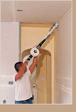
Mechanical drywall taping tools are commonly referred to as Bazooka® tools, after a popular brand, and they can be rented, usually for 2 weeks at a stretch. The suite of tools includes a taper that applies tape and com­pound simultaneously, as well as finishing tools, various head attachments, and flat boxes for taping seams.

These tools are great for larger jobs, creating uniform, flat surfaces that need little sanding. "You can put tape and mud up almost as fast as you can run," notes one pro. Most rental com­panies supply a video on how to use these tools, but taking a class in addition isn’t a bad idea.

Give the repair three coats of compound, feath­ering out the edges as you go. Take it easy when sanding. Especially after the first coat, the tape frays easily. By the way, there are precut drywall patches for electrical outlet boxes, which save time.

Large holes should be cut back till you reach solid drywall. Because mesh tape and compound will probably sag if the hole is much wider than 4 in., holes larger than that should be filled with a patch of drywall roughly the size of the dam­aged area. These patches need to be backed with something solid, so they’ll stay put.

The easiest backing is a couple of furring strips cut about 8 in. longer than the width of the hole and placed on both sides of the hole. To install each furring strip, slide it into the hole and, while holding it in place with one hand, screw through the drywall into the wood. Screws will pull the furring strips tight to the back of the drywall. Then cut the drywall patch, place it in the cutout area, and screw it to the strapping.

Cover the edges of the drywall patch with self­adhering mesh tape, fill the screw holes, and apply joint compound—three coats in all. Here, a setting-type compound, such as Durabond® 90, is a good bet because it dries quickly and is unlikely to sag. The more skillfully you feather the compound, the less visible the patch will be.

For holes larger than 8 in., cut back to the centers of the nearest studs. Although you should

Подпись: Drywall seams that coincide with door or window openings are likely to crack, vertically. That's merely a cosmetic problem. But large cracks running diagonally from the corners of windows or doors (inside or out) may be caused by foundation settling—a problem worth a closer look, perhaps by a structural engineer. For more information, see Chapter 1. 1111 image764image765

have no problem screwing a replacement piece to the studs, be sure to back the top and the bottom of the new piece. The best way to install backing is to screw drywall gussets (supports) to the back of the existing drywall. Then position the replace­ment piece in the hole and screw it to the gussets, using drywall screws, of course.

Discolored, crumbling, or moldy drywall is

caused by exterior leaks or excessive interior moisture. Be sure to attend to those causes before repairing the drywall. Excessive moisture is often due to inadequate ventilation, which is especially common in kitchens and baths. Leaks around windows and doors are often caused by inadequate flashing over openings.

If the drywall is discolored but solid, and if you’ve remedied the moisture source, wash the area with soap and water, allow it to dry thor­oughly, and prime it with white pigmented shel­lac or some other stain-resistant primer. The same solution works for minor mold on sound drywall.

However, if there’s widespread mold and the drywall’s crumbling, there’s probably extensive mold growing inside the walls. You’ll need to rip

out the drywall and correct the moisture prob­lems before replacing finish surfaces. In extreme cases, you’ll need to replace the framing. Chapter 14 covers mold abatement at greater length.

Plastering

This section is limited to plaster repairs because applying plaster takes years to master. The tools needed for plaster repair are much the same as those needed for drywall repair: a screw gun or cordless drill; 6-in. and 12-in. taping knives; a mason’s hawk; and a respirator mask, if you’ll be removing or cutting into plaster. There’s a lot of grit, so wear goggles, too. The tools and tech­niques for plaster are similar those needed for stucco, discussed in Chapter 7.

ANATOMY OF A PLASTER JOB

Traditional plastering has several steps:

1. Nail the lath to the framing.

2. Trowel a scratch coat of plaster onto the lath. The wet plaster of this coat oozes through

The norias

The hydraulic noria, sometimes called the current noria, first appeared in the period of the Roman Empire. Herein we simply call this the noria. The very first evidence is found in the description of Vitruvius (around 25 BC) as we have cited in Chapter 6. Vitruvius describes the machine very clearly, but says nothing about the location of the particular device. Moreover we are not aware of any other mention of the noria by Roman writers. The second piece of evidence is found in the very heart of the land that will become the location of the largest norias: it is in a mosaic discovered at Apamea, a Hellenistic and Roman city located some fifty kilometers to the north of Hama oppo­site the depression of Gharb where the Orontes flows. We know from a signature that this mosaic dates from 469 AD. It is unusual to find machines represented in mosaics, suggesting that during this period the noria was considered to be an important element of the patrimony of the region. The tradition persists to this day, since even now the city of Hama maintains and renovates its norias. The accounts of Arab travelers in the 12th and 13th centuries, cited earlier in this chapter, speak of beautiful norias in the same breath as the Orontes and the city of Hama. Ibn Battuta, in the course of his grand voy­age, observes norias at Amasya in Anatolia, on the Karan and the Fars, at Samarcand and even at the mouth of the Ganges. He mentions that they also can be found in China (but surely did not see them himself). As we have described earlier, norias are also

The norias

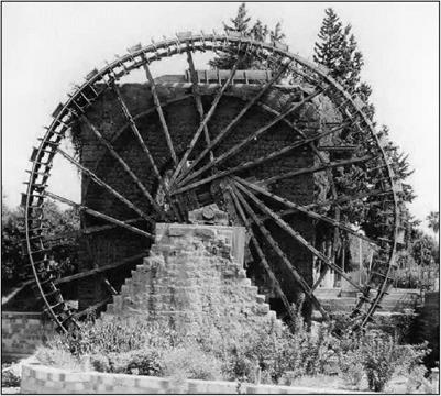
Figure 7.18 Detail of the wheel of the al-Damalik noria at Hama (note in particular the paddles and runnels). In the background is the wheel of the al-Hudura noria. (photo by the author).

The norias

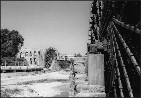
Figure 7.19 In the foreground, the axle of the noria al-Gisriyya at Hama; and in the background the noria of al-Mamuriyya, dating from 1453. Prior to its first reconstruction, this latter noria was the second largest in size (after the noria of al-Mohammadiyya). (Photo by the author).

found in Andalusia (Toledo, Cordova) and at Fez. Still, in the eyes of these travelers, none of those norias are as remarkable as those found at Hama.

Norias are machines that can lift water to a great height, but they are also very expensive. They are thus best suited for implementation on rivers of fairly regular dis­charge, flowing in a well-defined course, and having rather steep banks – and at sites where gravity irrigation would be otherwise difficult. The norias of the Orontes have been particularly well studied.[362] The typical machine comprises a narrow wheel whose diameter depends on the desired lift. As is the case for its ancestor the lifting wheel, the noria has wooden water boxes or jars, on its perimeter to lift the water. The paddles are mounted on the outside circumference of the wheel; on the Orontes, these paddles are spaced at approximately 50 cm, whatever the diameter of the wheel. Rotation of the wheel is induced by the river current, channeled through a canal scarcely wider than the wheel itself and impinging on these paddles. On modest rivers such as the Orontes or the Khabur, an overflow dam raises the water level at the entrance to this canal, thus aug­menting the speed of the current that drives the paddles.

The water boxes have an opening in the side (Figure 7.18). The boxes fill with water when they are immersed in the canal; then, when at the top of the rotation of the wheel, they pour their water out into a trough parallel to the wheel, at the top of the structure

The norias

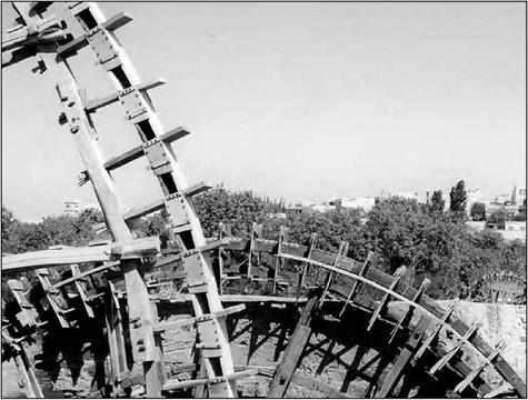
Figure 7.20 Spoke structure of the noria al-Gisriyya at Hama (photo by the author).

called the “tower”. The trough becomes an aqueduct that delivers the water to the dis­tribution system. The tower and aqueduct are easily visible on Figure 7.7, as well as on the remains of the norias of Khabur (Figures 7.12 and 7.13). One end of the wooden axle of the noria rotates in a notch that is part of the tower; the other end rotates on a support that is, on the Orontes, a triangular masonry structure (this “triangle” is clearly recognizable in the mosaic at Apamea, see also Figure 7.19).

A single dam can accommodate several norias (Figure 7.8) and a single noria can moreover be fed by several supply canals (Figure 7.13), each dedicated to one wheel. If these wheels are of different diameter then each has its own outlet trough; if not, they can pour their water into the same trough. Often one can take advantage of the dam to install a mill as well (Figure 7.12).

One finds the largest known norias at Hama – those called al-Mohammadiyya and al-Mamuriyya, dating from 1361 and 1453. Their wheels are approximately 21 m in diameter. On rivers subject to destructive floods, for example the Euphrates, there is no need to bring excessive care and quality to the construction of the wheels as they are most often destroyed by the annual flood and thus must be rebuilt each year. On the other hand on the Orontes, a river of quite regular flows, the wheels are built with great care. Large and narrow, they are trued to an astonishing precision (several centimeters on wheels from 10 to 20 m in diameter). They are serviced each year at the end of the irrigation season. Their wooden arms are not radial, but are laid out in an arrangement that is common to all the wheels, but particularly those of the Orontes, an arrangement that is clearly visible on Figure 7.20.