FOUNDATIONS

The foundation for a luminaire pole must provide sufficient resistance to overturning moments caused by the static load of the mast arm plus a wind and/or an ice load. It must be capable of maintaining the correct alignment of the luminaire and able to withstand the impact should the pole be struck. For breakaway poles, the foundation must be rigid enough to allow the breakaway device to operate while not becoming a hazard itself.

Luminaire foundations are perhaps one of the most dangerous constructed hazards on the right-of-way. This is due to their placement or location, structural design, and unsafe wiring systems. Historically, pole foundations have been poured-in-place concrete with steel reinforcing rods and anchor bolts. The requirement that upon breakaway nothing shall project more than 4 in (100 mm) above a chord line drawn between two points 5 ft (1.5 m) apart has caused redesign of concrete foundations. It has been rec­ognized for several years that a problem exists when a foundation is placed on a slope. As early as 1985, a memorandum was issued stating that designers should not allow the slope between the travelway and the foundation to be greater than 6:1. This is even more effective when the diameter of the foundation is as small as possible, thus limit­ing the concrete protruding above the grade line. Eliminating the transformer base allows the foundation to be sized to accommodate the pole bolt circle, which in most roadway size poles is considerably less than the bolt circle for a transformer base. In order to do this, the electrical circuit elements that were formerly housed in the T-base— i. e., splices in the conductors, fuse holders, and surge arresters—must be relocated underground. This requires that the electrical components be capable of being fully submerged and remain watertight. Figure 7.68 provides an example of a small-diameter concrete foundation and adjacent underground electrical junction box design.

LUMINAIRE CABLE & CONNECTOR (ORANGE. MALE)

POWER

CABLE

BREAKAWAY JUNCTION BOX COUPUNG SIMILAR TO TYPE 1 WITH WITH COVERS LIGHT DUTY COVER OR SUP BASE,

зг-mm CONDUIT TO POLE "

NONMETALDC

CONOUIT

GROUNO ROO

DISTRIBUTION BLOCK (RED)

CLEARANCE (TYPICAL FOR ALL REINFORCWG STEEL)

Auger bases are an effective method of reducing diameter of the foundation. Many states use a galvanized steel auger base foundation instead of concrete. Most concrete foundations require 3 in (75 mm) of concrete outside the anchor bolts to provide the necessary strength. Even if the T-base is eliminated, a concrete foundation is 6 in (150 mm) larger in diameter than the pole base it serves. The flat steel top of the auger base foundation can be the same size as the pole base, which minimizes foundation size. Another advantage of the auger base foundation, with the circuit elements under­ground, is the resistance to damage when an accident breaks the pole. When a concrete foundation, with its anchor bolts poured in place, has one bolt damaged, the entire founda­tion should be replaced. The auger base foundation uses relatively short bolts, which are replaceable if damaged. Auger base foundations are easily installed by the electrical crew using the same auger trucks used to drill the hole for the concrete shaft. Electrical crews are not called upon to tie reinforcing steel, set and properly align anchor bolts, or finish the concrete—all tasks that require skill to perform properly. It has been reported that a two – worker crew can install 8 to 10 auger base foundations per day, resulting in significant labor savings. A diagram of the auger base foundation with underground electrical junction box is provided in Fig. 7.69.

Pole foundations cannot always be installed on a 6 to 1 slope, as described in many publications by the FHWA as being necessary to ensure the proper operation of a pole breakaway device. To meet the requirement that no part of the foundation or remaining stub of a breakaway device extend no more than 4 in (100 mm) above a theoretical line connecting possible tire tracks 60 in (1525 mm) apart, it is desirable to reduce the diameter of the foundation. If a concrete foundation is 30 in (760 mm) in diameter, then on a 6 to 1 slope, which is the very best condition expected, there will be 5 in (125 mm) of concrete protruding above the ground plus the anchor bolts and the remaining por­tion of the breakaway device after breaking. Figure 7.70 shows a conventional trans­former base installed on a concrete foundation. A 17-in (430-mm) bolt circle is normal for the current transformer base design and 3 in (75 mm) of concrete is needed outside

LDMINAIRE CABLE & CONNECTOR (ORANGE, MALE)

32-mm CONDUI TO POLE

SHAFT DIAMETER AND LENGTH SHALL BE DETERMINED BY THE SOL TYPE AND THE TOTAL OVERTURN MOMENT OF EACH POLE

HEUX SHALL HAVE A 75 mm PITCH. ALL RADIAL SECTIONS NORMAL TO AXIS (і 3 DEG). / HEUX MUST BE FORMED BY MATCHING METAL DIE,

FIGURE 7.69 Auger base luminaire foundation system with underground modular cable distribution system. Dimensions shown as mm. Conversions: 25 mm = 1 in, 32 mm = 1.25 in, 50 mm = 2 in, 64 mm = 2.5 in, 75 mm = 3 in, 90 mm = 3.5 in, 150 mm = 6 in, 255 mm = 10 in, 305 mm = 12 in.

DIAMETER

FIGURE 7.70 Details of conventional transformer base installed on concrete foundation. (Note: Does not meet latest AASHTO recommendations.)

the bolt circle for strength, resulting in a foundation diameter of 23 in (580 mm). Although there are thousands of existing installations of this type still in service, this design (Fig. 7.70) does not meet the recommendations of the latest AASHTO structural supports specifications for protecting the wiring and the fuses from possible damage when impacted by a vehicle.

The foundation design shown in Fig. 7.71 incorporates the flush-mounted junction box made possible by the submersible wiring system. This allows the bolt circle to be reduced to that required by the pole base plate, usually in the range of 11 to 13 in (280 to 330 mm). The smallest foundation that can be provided is a steel plate that is the size of the pole base. This is attached to a steel shaft that extends into the soil approxi­mately 5 to 8 ft (1.5 to 2.5 m) deep. This foundation design including the submersible wiring is shown on a 3 to 1 slope in Fig. 7.72. These foundations are available from several sources including Dixie Division of Aluma-Form [15] and the A. B. Chance Company [16]. Such a foundation is combined with the flush grade mounted junction box and the submersible Modular Cable System and either a frangible coupling or a slip base pole to achieve an effective breakaway lighting pole installation. Lighting designers cannot always influence the design of a roadway’s shoulders and front slopes, but by using this foundation, designers do all within their power to ensure requirements of the AASHTO Roadside Design Guide are satisfied.

The Modular Cable System mentioned is recommended for use in both breakaway and nonbreakaway pole bases. Because there is only one splice to be made at each pole, with the other connections made by plug-in connectors, the time required to install and the skill level needed of the installer are minimal. Also, when troubleshooting a defec­tive circuit, it is a great advantage to be able to unplug the various circuit elements rather than deal with permanent splices.

MOLDED PLUG & CONNECTOR (ORANGI-

JUNCTION BOX

DISTRIBUTION BLOCK (RED)

Experimental Pavement and Modelling Hypotheses

In the European project SAMARIS, the predictions obtained with ORNI have been compared with the response of a low traffic pavement tested on the LCPC pavement test track. The pavement consisted of:

• a bituminous concrete wearing course, with an average thickness of 66 mm;

• A 50 cm thick granular base and sub-base (crushed gneiss);

• A clayey sand subgrade (thickness 2.20 m), resting on a rigid concrete slab.

As in the previous example (Section 11.4.5) the pavement was instrumented to measure strains, temperatures and water contents in the various layers. The loading consisted in applying 1.5 million heavy vehicle loads (dual wheels, with a load of 65 kN).

In the modelling of the resilient behaviour (with CVCR), the bituminous concrete and the soil were assumed linear elastic, and the UGM was described using the anisotropic Boyce model (Eq. 9.13). The bituminous concrete moduli (function of temperature and loading frequency) were determined from complex modulus tests, the UGM and soil parameters from repeated load triaxial tests.

In the modelling with ORNI, it was assumed that no permanent deformations occur in the thin bituminous layer. The permanent deformations of the UGM and of the soil were described using the empirical model of Gidel et al. (2001), with model parameters determined from repeated load triaxial tests, at two water contents for the UGM (w = 4% and 5%), and one water content for the soil (w = 11%).

Figure 11.17 shows the finite element meshes used to determine the resilient behaviour with CVCR (in 3D), and then the permanent deformations (in 2D).

Fig. 11.17 Finite element meshes used for the modelling of the experimental pavement

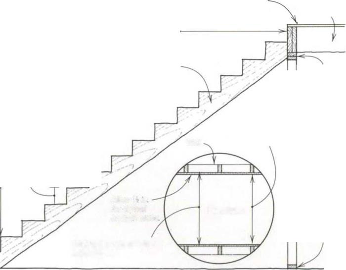
Determining total rise and run

One of the most important parts of stairbuilding is to determine the total rise, or vertical distance between finish floors that are connected by a stairway (see the drawing on p. 160). While figur­ing the distance between the two floors is simple, a problem can arise because stairs are usually built before the finish floors are in place. So the measurements are actually taken from rough floor to rough floor but must account for the finish floor material at both the top and bottom.

I once built several stairs in an apartment house, not realizing that the plans called for ІУ2-ІП. lightweight fire-resistant con­crete on the upstairs landings. I was called back to explain why every riser was 7 in. except the last, which became 8У2 in. once the concrete was poured. The next day I tore out the stairs and started over.

There are other problems when figuring total rise, especially for exterior decks and remodeling. Usually when I measure total rise, I hook my tape on the upper floor, pull it straight down to the lower floor, and read the measurement. But remember that the first tread lands a set number of horizontal feet away from the last tread. What’s more, the floor or the ground between these two points may be sloping considerably. So for accuracy, carefully level straight out from

111/2-in. (2×12) joist

%-in. subfloor


130-in. stairwell opening


Determining total rise and run

Подпись: 3-in

Total number of risers: 15 Total number of treads: 14

Stringer

921/4-in.

wall

stud

plates


Finished stair width 36 in


10-in. tread


Wall


6-ft. 8-in. headroom


7/4-in. riser


109-in. total rise from finish floor to finish floor


Allow V? in for drywall on both sides


Plan view


1У2-ІП.

bottom

plate


Stairwell rough opening width: 37 in.

140-in. total run (14 10-in. treads)

the upper floor landing to a point directly over the lower landing before making the total rise measurement.

Unlike the total rise, which is a fixed number, the total run, or horizontal dis­tance, can vary for a given set of stairs (see the drawing). This is important because treads can be made narrower or wider to allow the stairway to fit into the allotted space. While most straight – flight stairs run about 12 ft. on the level, the number of treads and their width determine the exact total run. If each tread is 10 in., for example, and the stair has 14 treads, then 10 in. x 14 = 140 in. for a total run of 11 ft. 8 in.

Example of Modelling of Permanent Deformations

The modelling of permanent deformations of pavements is more complex than the modelling of the resilient behaviour because it is necessary to simulate the response of the pavement to large numbers of load cycles (typically 105-106 cycles), with variable loading and environmental conditions.

A programme for the prediction of rutting of low traffic pavements, called ORNI, is also implemented in the finite element code CESAR-LCPC (El Abd et al., 2005; Hornych & El Abd, 2006). To determine the permanent deformations due to large numbers of load cycles, this programme proposes a simplified approach, based on a separate calculation of the elastic response and of the plastic strains. It comprises 3 steps:

i) The first step consists in calculating the resilient response of the pavement, for the different loading conditions considered (different types of loads, different temperature, etc…). The resilient response is calculated in 3D, using the pro­gramme CVCR.

ii) Then, the resilient stress fields are used to calculate the plastic strains pro­duced by the successive application of the different loads. The permanent strains are calculated locally, at different points in the pavement structure, in 2D (in the plane (0,y, z) perpendicular to the direction of displacement of the load).

iii) Finally, the third step consists in calculating the displacements in the pave­ment structure. The plastic strains being calculated locally, at different points, do not derive from a displacement field. It is thus necessary to determine the total strains, ensuring their continuity and integrability, and the corresponding displacements.

Two permanent deformation models are implemented in ORNI: the empirical model of Gidel et al. (2001), and the elasto-plastic model of Chazallon (Chazallon et al., 2006). These models have been described in Chapter 9.

STEP 4 Install the Corner Bead

Once all the drywall is in place, metal or vinyl corner bead is installed on all outside corners, including wall corners, window wraps, closet doorways, and the attic access hole. This bead protects corners from impact and forms a straight, finished edge. Both metal and vinyl

w


1

Finish Carpentry

After framing and

wires, insulating, and hanging drywall, it’s time to install interior trim. Somewhat like a picture frame, trim is decorative. But it’s also functional, concealing gaps and rough edges where walls meet floors, ceilings, doors, and windows. Although finish carpentry is not as fundamental as structural framing or foundation work, it com­pletes the picture, and often makes or breaks a renovation project.

Interior trim is often called casing, or molding if its face is shaped. Trim helps establish the character of a room, so it’s wise to respect exist­ing trim when replacing or supplementing it. Carefully remove and save existing molding if it’s in decent condition. If that type is no longer available, try to locate new molding with a simi­lar feeling. Or you might be able to combine and overlap stock moldings to create a more complex and interesting look. Another choice is using pre­
fab, high-relief synthetics that duplicate large – scale moldings not available in wood today.

Many woodworkers and carpenters can re-create old trims. A homeowner who’s good with a router and can find the right bits may be able to do the same.

Finally, see Chapter 13, for concise advice on choosing and installing counters, cabinets, and fixtures appropriate to those rooms. For guid­ance on installing door and window hardware, read Chapter 6.

Tools

Most of the tools for finish carpentry are presented in the basic collection discussed in Chapter 3, though upcoming sections address a few specialty tools. Still, by and large, successful trimwork depends more on the hands behind the tools than on the tools themselves. Also, when working with power tools and striking tools, safety glasses are

Trim covers gaps between building materials and dresses up a room. Here, baseboards are shimmed ’/> in. above a concrete basement subfloor so carpet can be tucked under it. Pneumatic nailers are much faster than hand nailing and far less likely to split or dent trim.


image834

image835STANtXV

Measuring and layout tools. 1, Framing square; 2, string; 3, adjustable square; 4, stud-finder; 5, combination square; 6, adjustable bevel; 7, steel try square; 8, chalkline; 9, folding rule with sliding extension; 10, tape measure;

11, compass; 12, Swanson Speed Square.

Подпись: PROnP Get organized. Before you begin, set up a workstation with all the tools and materials you'll need. Keep the area clean and your materials sorted: Clutter and chaos eventually lead to wasted time and costly mistakes. 1111

a must, especially when joinery requires close work at eye level.

Shower Curtains and Liners

New PVC liners and shower curtains have a strong odor from outgassing toxins. Many shower curtains are treated with harmful chemicals to create mildew resistance. Cotton duck cloth shower curtains are naturally water repellent, wrinkle resistant, and attractive but they take a long time to dry and must be treated to resist mildew growth. They can be machine washed and dried. They are available through several mail order companies includ­ing Gaiam and Heart of Vermont. Natural hemp curtains are now available through Real Goods. A glass shower enclosure, although more expensive to install, will be a permanent, low-maintenance, and healthy solution.

Beds and Bedding

The most important furniture decision with regard to health is the choice of beds and bed­ding. We spend approximately a third of our lives in bed. Infants and children spend even more time there. While we sleep, our noses are in close contact with our bedding.

Standard mattresses are made of synthetic fabrics and padding and treated with petro­chemical fire retardants. A bed that promotes health should have many of the same charac­teristics as a home that promotes health. The bed should be:

• nontoxic

design and green and healthy practices. This was a natural progression for Cisco Brothers, a company that has always been socially responsible, provid­ing employment through apprenticeship pro­grams to underdeveloped communities in South Los Angeles since the early 1990s.

Simultaneously, I set about trying to find suit­able fabrics produced without the chemicals used in standard agriculture. Cotton is the world’s most importantfibercropand one of its most important cash crops. It is also one of the most intensively sprayed field crops. In the United States, accord­ing to the US Department of Agriculture, more than 53 million pounds of pesticides and 1.6 bil­lion pounds of synthetic fertilizers were applied to cotton fields in 1996. In California, cotton pro­duction ranks second for the total amount of pes­ticides used.

Organic farmers practice soil building with cover crops and composting, crop rotation, and safe and effective pest and disease control. Weed management means hoeing by hand, and instead of using defoliants organic farmers rely on a hard freeze to defoliate the cotton.

Eco-terric’s exclusive collection of organic Ka – lamkari fabrics comes from a small fair-trade vil­lage operation in the southwest of India. This is an ongoing endeavor in conjunction with the ar­tisans, and features organic cotton dyed with 100 percent natural dyes. All solids are hand-woven, and all prints are block-printed by hand. The nat­ural beauty of these fabrics, combined with the timeless art and craftsmanship of the Kalamkari tradition, has made this collection the perfect complement to our mission of bringing natural beauty with color to the home.

• able to absorb and dispel moisture without supporting mold or mildew growth

• easy to clean and sanitize

• nonconductive of electricity (free of metal)

• highly insulative

The following futon bedding system fulfills these characteristics. The mattress is made of layers. One or more 1- to 4-inch-thick un­treated organic cotton futons are topped with a 1- to 3-inch wool futon. The layers rest on a slatted frame raised above the floor to a com­fortable seating height. The cotton futon pro­vides firm back support, while the wool futon adds resilience. Varying the thickness and the number of layers will accommodate different firmness preferences.

To properly maintain a futon, it should be

aired weekly in sunlight to sanitize it and then fluffed and replaced in a rotated position so it will wear evenly. A bed made of thin futons has an advantage over a single thicker mat­tress because the layers can be easily lifted and carried. It is important that air be allowed to circulate under the futon to facilitate evapora­tion of moisture, thereby preventing mold or mildew growth. A slatted platform will hold the futon firmly in place and permit air circu­lation around it.

Since the first edition of this book was published, many organic, metal-free mattress options have become available. These mat­tresses often are made of a combination of nat­ural latex, wool, and organic cotton. This com­bination system conforms to the body shape and comes in a variety of firmnesses offering

I have been saddened on many occasions by stories of cotton farmers in India whose lives are made virtually unbearable by health problems re­sulting from constant contact with pesticides and by huge debts owed to the giant chemical com­panies. It was tremendously exciting to receive the news that Srinivas Pitchuka, owner of Bundar Ka – lamkari House and Syamala Arts and Crafts, with whom I have worked on our collection over these past years, was the recipient of an award for being the first company in his province to produce or­ganic textiles.

I will continue to search for ways to produce furnishings and textiles that not only enrich our health and our homes but also care for our planet and those who work on it.

Rowena Finegan, BBEC, owner and founder of Eco-terric, strives to create beautiful, colorful, and environmentally friendly living spaces using healthy materials that are also socially responsible. After studying Bau-Biologie, Rowena was inspired to open her first Eco-terric store in Bozeman, Mon­tana, in 2005. The newest location is at The Green Home Center on Polk Street in San Francisco. She collaborated with Cisco Brothers of Los Angeles to create the Inside Green furniture collection. She is also creating a line of organic textiles suitable for use in home decor. Rowena is a contributing writer to Green*Light magazine and has been featured in the Son Francisco Chronicle, Furniture Today and Helena Lifestyles. See eco-terric. com.

CASE STUDY 12.1

A HIP FRAMING WITH TRUSSES

Framing a valley with trusses is a simple matter of attaching a series of progressively smaller trusses to the top chords of the trusses of the main roof. The main-roof trusses do not have to be oversize since the only extra weight they will cany is the dead weight of the jack trusses themselves. Simple as this system is, many builders still prefer to frame these roof inter­sections as a farmers valley (see 137) with solid-sawn lumber.

VALLEY FRAMING WITH TRUSSES

Valley Jack Trusses

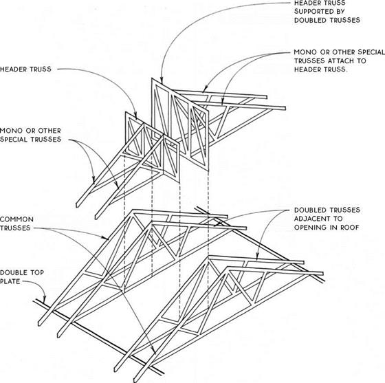
Rectangular openings for skylights or chimneys may be constructed in a truss roof. Small openings less than one truss space wide may be simply framed between trusses as they would be in a rafter-framed roof (see 135-136). Openings up to three truss spaces wide are made by doubling the trusses to either side of
the opening and attaching header and mono or other special trusses to the doubled trusses. Larger openings (more than three truss spaces wide) require specially engineered trusses in place of the doubled trusses. Obviously, it is most efficient if the width and place­ment of the opening correspond to truss spacing.

OPENINGS IN TRUSS ROOF

Headers between Double Trusses


A HIP FRAMING WITH TRUSSESA HIP FRAMING WITH TRUSSES

A HIP FRAMING WITH TRUSSES

WITH SHEATHiNG


A HIP FRAMING WITH TRUSSES

THERMAL EXPANSION

Thermal expansion can occur in pipes when there are temperature fluctua­tions. Damage can result from this expansion if the pipe is not installed prop­erly. In order to avoid damage, refer to Figures 11.7, 11.8, and 11.9 to learn about the tolerances needed for various types of pipe (Fig. 11.10).

THERMAL EXPANSION

Coefficient

Pipe material

in/in/°F

(°С)

Metallic pipe

Carbon steel

0.000005

(14.0)

Stainless steel

0.000115

(69)

Cast iron

0.0000056

(1.0)

Copper

0.000010

(1.8)

Aluminum

0.0000980

(1.7)

Brass (yellow)

0.000001

(1.8)

Brass (red)

0.000009

(1.4)

Plastic pipe

ABS

0.00005

(8)

PVC

0.000060

(33)

PB

0.000150

(72)

PE

0.000080

(14.4)

CPVC

0.000035

(6.3)

Styrene

0.000060

(33)

PVDF

0.000085

(14.5)

PP

0.000065

(77)

Saran

0.000038

(6.5)

CAB

0.000080

(14.4)

FRP (average)

0.000011

(1.9)

PVDF

0.000096

(15.1)

CAB

0.000085

(14.5)

HDPE

0.00011

(68)

Glass

Borosilicate

0.0000018

(0.33)

FIGURE 11.7 ■ Thermal expansion of piping materials. (Courtesy of McGraw-Hill)

Temperature Change (°F)

Length (ft)

40

50

60

70

80

90

100

20

0.278

0.348

0.418

0.487

0.557

0.626

0.696

40

0.557

0.696

0.835

0.974

1.114

1.235

1.392

60

0.835

1.044

1.253

1.462

1.670

1.879

2.088

80

1.134

1.392

1.670

1.879

2.227

2.506

2.784

100

1.192

1.740

2.088

2.436

2.784

3.132

3.480

Подпись: Temperature Change (°F) Length (ft) 40 50 60 70 80 90 100 20 0.536 0.670 0.804 0.938 1.072 1.206 1.340 40 1.070 1.340 1.610 1.880 2.050 2.420 2.690 60 1.609 2.010 2.410 2.820 3.220 3.620 4.020 80 2.143 2.680 3.220 3.760 4.290 4.830 5.360 100 2.680 3.350 4.020 4.700 5.360 6.030 6.700

FIGURE 11.9 ■ Thermal expansion of all pipes (except PVC-DWV). (Courtesy of McGraw-Hill)

Подпись: A hole in a pipe that is not more than .63 centimeters in diameter can result in a loss of 14,952 gallons of water a day! Even a pinhole leak can amount to a loss of over 18,000 gallons of water in a three-month period.

FIGURE 11.10 ■ Tech tips.

ELECTRICAL HAZARD

One problem that has recently been identified is the potential deadly threat posed by the electric circuits after pole impact by an errant vehicle. There are many documented deaths of motorists who survived the impact with a luminaire pole only to be subsequently killed from the resulting explosion and fire. The explosion and fire are usually caused when the fuel tank ruptures, the vehicle having been caught on an improperly constructed foundation, and the electrical system sparks repeatedly until the fuel explodes. In other incidences, medical personnel have been delayed from attending victims because of the risk of electrical shock from exposed conductors near or under a vehicle.

Past research efforts have concentrated on evaluating the structural breakaway characteristics of luminaire poles. In addition to the need for the pole itself to have breakaway ability, it is recognized that the underground wiring system should also be capable of properly separating. There are a number of reasons for requiring proper separation of the wiring system. One of these reasons is that the size, and associated tensile strength, of the wire cable is sufficient to significantly increase the deceleration rate of impacting vehicles and to also change the trajectory of the falling pole. Another reason is that improper separation of the electrical cabling can result in bare conductors that are still energized, posing an electrical and a possible fire hazard at the accident scene.

Early efforts to reduce electrical hazard concentrated on providing line fuses placed in a breakaway device. However, these widely used “breakaway fuse holders,” which for years have been the standard, have not been certified by testing. Prior expe­rience indicates that they frequently perform improperly during an accident situation. Rather than properly separating, the device frequently pulls off the wire, leaving an exposed end that is potentially deadly. Part of the problem with the breakaway fuse holder is the location of the device in the pole or T-base and the 24 to 36 in (610 to 910 mm) of distribution cable inside the base. This extra length of wire is placed in the pole to allow service crews the ability to pull the wire out of the pole and make the connections to the luminaires. Upon impact this extra length of wire obstructs proper separation of the breakaway fuse, and allows the wiring insulation to be damaged by the fractured pole. The resulting bare electrical conductor poses a safety hazard because of the relatively large voltages used in underground roadway illumination systems.

Most luminaire underground wiring systems operate on 480 V. The reason for using 480 V is that the voltage drop in the copper conductors that supply a given load is only one-fourth the value of the voltage drop when using 120 V and one-half that of 240 V. In addition, luminaires are designed to perform within a certain percent of the rated voltage. Thus for a given percent, such as 10 percent, the allowable drop would be 4 times greater for a 480-V circuit than for a 120-V circuit (48 versus 12 V) or twice that of a 240-V circuit. These factors are additive, so a 480-V circuit requires a much smaller copper wire to deliver the necessary amount of energy over a long dis­tance. Using 480 V is desirable, but proper precautions and installation techniques must be used to reduce the inherent hazard on the public right-of-way.

FIGURE 7.67 MG2/Duraline modular pole cable system.

A modular cable system initially developed by MG2 Inc. and Duraline Inc. elimi­nates a number of problems presented by the current wiring method [14]. This cable system is a submersible, modular plug and cable system that allows the circuit compo­nents (i. e., the low-amperage, fast-acting, current-limiting fuses; the surge arrester where desired; and the conductor splices) to be placed in an underground junction box adjacent to the pole foundation. The circuit breakaway connector can be positively positioned at the top edge of the conduit inside the pole base. Since the stiff, typically no. 4 or no. 6 copper, conducting cables never enter the pole, the system unplugs at ground level. The impact that knocks down the pole will not put stress on the electri­cal cables and will not weaken splices in adjacent poles. Most important, with the modular cable assembly, there is no exposed electrical hazard upon knockdown as can exist with the conventional wiring method. When this system (Fig. 7.67) is combined with a properly installed foundation, the possibility of fire and explosion or electrical shock is significantly reduced if not eliminated. Recent developments have shown that the splices, the surge arresters, the fuse holders, and the ground rod must be placed underground in a junction box adjacent to the pole base to provide the greatest possible degree of safety. This requires that all components be submersible. This design will positively place a breakaway connector in the wiring system at the top edge of the foundation; the fuses are underground, where no damage can occur on the supply side. The Modular Cable System developed by MG2/Duraline was the first of these sub­mersible wiring systems on the market and has proven to be very reliable [14]. By using fast-acting, current-limiting fuses installed below ground, the potential for elec­trical shock and fuel explosions is greatly reduced if not eliminated.

The AASHTO Standard Specification for Structural Supports for Highway Signs, Luminaires, and Traffic Signals, 4th ed. (2001) has included some positive statements strongly encouraging the use of this submersible-type wiring system for all breakaway poles.